Embed Size (px)
Citation preview
1398 IEEE TRANSACTIONS ON MAGNEXICS, VOL. 28, N0.2, MARCH 1992
3D ELECTROMAGNETIC MODEL OF A FULL SUPERCONDUCTING GENERATOR
P.G. THEROND - 0. MOREAU - C. KENY ELECTRICITE DE FRANCE
DIRECTION DES ETUDES ET RECHERCHES Service Matdriel Electrique
1 Avenue du GCndral de Gaulle 92141 CLAMART CEDEX - FRANCE
ABSTRACT
2he aim of this paper is a three dimensionnal electromagnetic modelization of a full superconducting generator. In a first stage, magnetic field calculations by two diyerent methods (analytical and finite element) are given for a single winding surounded by an iron core. The results are compared between the two methods and with experimental results. In a second stage, results are given for a ful l generator in stady state, in tenns of characteristic reactances of the machine and magnetic fields in the end region.
1. INTRODUCTION
The first designs of 50/60 Hz superconducting wires with reasonable losses 113 [2] extended the range of eventual applications of superconducting materials to power engineering. Full superconducting generators [3] [4] using both a superconducting field and armature winding could be one of these applications.
, mognrtic circuit
superconducting field winding Ib) and full superconducting generator (IC) (taken from 131).
. rlrclromagnrtic shirtd
Winduq
I
shield
A correct electromagnetic modelization of such a machine is essential for two reasons. First one concems, like all other machines, the determination of its characteristic electrical parameters, conditionning its behavior on the network. Second one is more specific to superconducting generators. It concems the calculations of the magnetic field on the annature windings, conditionning their losses. This last parameter is of course very important for the design and characterization of the machine. Due to its air cored character (see fig. 1) this kind of superconducting machine has essentially a 3D electromagnetic behavior. Therefore, to achieve a correct determination of the parameters given before, 3D calculations has been developped as described in the paper.
The general structure of the machine is given on Figure 1. Figure 2 gives typical winding geometries and Table 1 gives the main dimensions. Basically the electromagnetic problem reduces to a one phase (field winding) and a three phased (armature winding) saddle shaped windings interacting with a highly permeable iron core. To solve t h i s problem, the following procedure has been followed. In a first stage, we performed an electromagnetic modelization of a single saddle shape winding surrounded by an iron core. The results have been verified by a comparison between two calculation methods and with experimental datas [5]. In a second stage, the currents in the different windings are calculated for a given state. At the end, the 3D electromagnetic modelization of the full m a c h e at steady state is performed. b
b
:Typical saddle shaped windings
2.MAGNETIC FIELD PRODUCED BY A SINGLE SADDLE SHAPED WINDING SURROUNDED BY AN IRON CORE
Two methods were used for the determination of the field produced by a saddle shaped winding. Both methods use a surfacic representation of the winding, which is the most appropriate to our case : on one hand, due to the small section of the conductors &gh current densities), a volumic representation would be unrealistic. On the other hand, a single "wire" representation isn't appropriate since one of the aims of the modelization is to calculate the field on the windings, which goes to infinity in the case of a "filament" representation.
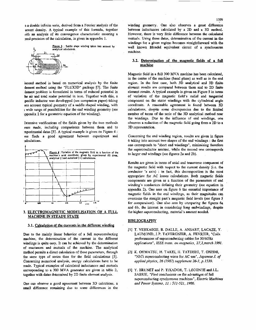
First method derives from a complex analytical formula [SI [6] giving the magnetic field produced by a simplified saddle shaped winding shown on figure 3, surrounded by an infinitely long and infinitely permeable iron core. This formula consists
Manuscript received July 7,199 1. 0018-9464/92$03.00 0 1992 IEEE
1399
~1 a double infinite serie, derived from a Fourier analysis of the urrent density. A typical example of this formula, together vith an analysis of its convergence characteristic ensuring a rood precision of the calculation, is given in appendix 1.
m& : Saddle shape winding taken into account by uulpical calculatiohc.
iecond method is based on numerical analysis by the finite dement method using the "FLUX3D" package [7]. The finite :lement problem is formulated in terms of reduced potential in he air and total scalar potential in iron. Together with this, a ;pecific inductor was developped (see companion paper) taking nto account typical geometry of a saddle shaped winding, with I wide range of possibilities for the end winding geometry (see tppendix 2 for a geometric equation of the winding).
3xtensive verifications of the fields given by the two methods Mere made, including comparisons between them and to :xperimental datas [5]. A typical example is given on Figure 4 : )ne finds a good agreement between experiment and :alculations.
Elel+:" ariation - of the magnetic field IS a hnction of the machine 5 uid wordinate, given by experimental (0) dam. analytical (-) and numeriul (+) ulculations.
I
I
I
l e am 0.1 on
3. ELECTROMAGNETIC MODELISATION OF A FULL
winding geometry. One also observes a great difference between inductances calculated by a 2D and a 3D method. However, there is very little difference between the calculated mutuals. Using these datas, determination of the current in the windings for a given regime becomes straightforward with the well known Blonde1 equivalent circuit of a synchronous machine.
3.2. Determination of the magnetic fields of a full machine
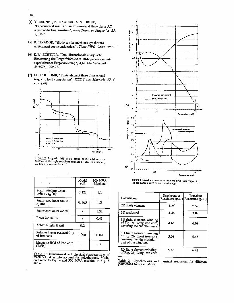
Magnetic field in a full 300 MVA machine has been calculated, in the center of the machine (basal pIane) as well as in the end region. In the first case, both 3D analytical and 3D finite element results are compared between them and to 2D finite element results. A typical example is given on Figure 5 in terms of variation of the magnetic field's radial and tangantial component on the stator windings with the cylindrical angle coordinate. A reasonable agreement is found between 3D calculations, despite some discrepencies due to the limited number of terms of the serie of the 3D analytical method near the windings. Due to the influence of end windings, one observes a reduction of the magnetic field going from a 2D to a 3D representation.
Concerning the end winding region, results are given in figure 6 taking into account two shapes of the end windings : the first one corresponds to "short end windings", minimising therefore the superconductor amount, while the second one corresponds to larger end windings (see figures 2a and 2b).
Results are given in terms of axial and transverse component of the magnetic field with respect to the current density (i.e. the conductor 's axis) : in fact, this decomposition is the most appropriate for AC losses calculations. Both magnetic fields components are given as a function of the parameters of end winding's conductors defining their geometry (see equation in appendix 2). One sees on figure 6 the essential importance of magnetic fields in the end windings, as their magnitudes can overcome the straight part's magnetic field levels (see figure 5 for comparaison). One also sees by comparing the figures 6a and 6b, the interest in considering long endwindings, despite the higher superconducting, material's amount needed.
MACHlNE IN STEADY STATE BIBLIOGRAPHY
3.1. Calculation of the currents in the different winding
Due to the mainly linear behavior of a full superconducting machine, the determination of the current in the different windings is quite easy. It can be achieved by the determination of reactances and mutuals of the machine. The analytical method permits a direct calculation of these parameters, through the same type of series than for the field calculations [5]. Concerning numerical analysis, energy calculations have to be made. Typical examples of calculated inductances and mutuals corresponding to a 300 MVA generator are given in table 2, together with datas determined by 2D finite element analysis.
One can observe a good agreement between 3D calcutions, a small difference remaining due to some differences in the
T. VERKAEGE, B. DALLE, A. ANSART, LACAZE, Y. LAUMOND, J.P. TAVERGNIER, A. FEVRIER, "Coils performances of superconducting cables for 50/60Hz applications", IEEE trans. on magnetics, 27,2,march 1991.
K. OHMATSU, H. TAKEI, H. TATEISHI, T. ONISHI, "NbTi superconducting wires for AC use", Japanese J. of applied physics, 26 (1987) supplement 26-3, p . 1539.
Y. BRUNET and P. TIXADOR, T. EECONTE and J.L. SABRIE, "First conclusions on the advantages of full superconducting synchronous machines", Electric Machines and Power Systems, 11 : 51 1-521, 1986.
1400
0 . 0 1 0
[4] Y. BRUNET, P. TIXADOR, A. VEDRINE, "Experimental results of an experimental three phase AC superconducting armature", IEEE Trans. on Magnetics, 25, 2, 1981.
Statorwindin mean radius , ro (mf
Stator core inner radius, rs (m)
Stator core outer radius
Rotor radius, m
Active length 21 (m)
[5] P. TIXADOR, "Etude sur les machines synchrones entikrement supraconductrices" , Th2se INPG - Mars 1987.
Model 300MVA coil Machine
0.121 1.1
1.2 o. 165
1.32
0.45
0.2
[6] K. W. ECHTLER, "Drei dimensionale analytische Berechnung des Eregerfeldes eines Turbogenerators mit supraleitender Errgerwicklung " , A jidr Electrotechnik 58(1976), 259-271.
Calculation
2D frnite element
3D analytical
3D finite element, winding of Fig. 2a. Lon iron core, covenng the end windings
3D finite element, winding
covenn just the straight part of &e windings
3D finite element winding of Fig. 2b. Long iron core
of Fig. 2b. Short iron core
[7] J.L. COULOMB, "Finite element three dimensional magnetic field computation", IEEE Trans. Magnetic, 17, 6, nov. 1981.
*
I - 0
r 0,r I-
O
Synchronous Transient Reactance (P.u.) Reactance (P.u.)
3.25 2.57
4.46 3.87
4.66 4.09
5.08 4.46
5.48 4.81
Magnetic field of iron core (Tesla) 1.8 -
Relative linear permeability I of iron core
Table 1 : Dimensional and physical characteristics of machines taken into account for calcultations. Model coil refer to Fig. 4 and 300 MVA machine to Fig. 5 and 6.
1 3 - 0 g 1.2 - 0
: U i 1
0.8
06
0 4
0.2
A Poronctrr ( r o d )
Poromdcr (rod)
F e u r e 6 :Axial and transverse magnetic field (with respea.m the conductor's axis) on the end windings.
Table 2 : Synchronous and transient reactances for different geometries and calculations. -
1401
Appendix 1 : typical example of the analytical expression of the magnetic field created by a simplified saddle shaped winding : axial field in abscence of iron :
where r,, is the winding's radius r,&z the cylindrical coordinates of the point (in our case r<r, ) , c, a Fourier coefficient given by :
c * = s ( 1 )sin(?-y)sin(:l+y) nn kn-ngaI4d
kn n a kn n a sin-d+- sin-1-- (2) + kx+nga /4d ( g 4 ) ( g 4 )
where h i s the current density a the angular amplitude of the straight parts of the winding d the width of the winding (typically d=arJ4) 1 the axial length of the winding g a numerical parameter ( g>>l) I, and K, are modified Bessel functions type 1 and 2.
We recognize in (1) a typical Fourier analysis in 8 and a far less typical Fourier analysis in z, reflecting the method used for 3D computation [5], [6]. This last serie is computed by taking into account a finite number of elements, and by- estimating the rest of the serie as follows. This rest is given by :
taking into account :
br
kn e & ' " limIn(-r)=
we obtain
As r < r,, the corivcrgence of the serie is very rapid for r fro and a mean square root of the last term of the sene is a good over estimation of its rest
However, when r tends to r,, the convergence is much less rapid, the terms of the serie decreasing like 1/k2. In this case, the rest of the serie is greater than the mean square root of its last terms: therefore, calculation has to be made up to a very high range for a guarantee of a good accuracy.
In addition, we can notice in (3) that for a good convergence, the numerical paameter g has to be low enough with respect to r,, (respecting however g>>l [5][6]).
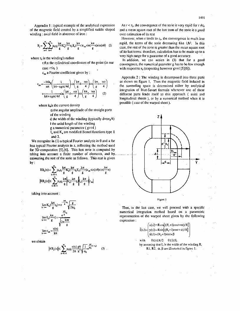
Appendix 2 : The winding is decomposed into three parts as shown on figure 1. Then the magnetic field induced in the surrending space is determined either by analytical integration of Biot-Savart formula whenever one of these different pnrts lends itself to this approach ( axial and longitudinal sheets ), or by a numerical method when it is possible ( case of the warped sheet ).
Figure 1
Thus, in the last case, we will proceed with a specific numerical integration method based on a parametric representation of the warped sheet given by the following expression : I x(t,l)= RcosE((R, +I)cos t +a ) / R]
f(t,l)= y(t,l)= Rsd((R, +l)cost+a)/R] - I z(t,l)= (R,+l)sin t + p with O l t S n / 2 O l l l L by assuming that L is the width of the winding R,
R1, R2, a, p are illustrated in figure 1.


![Fabrication and Installation of Radio Frequency System for ...[2] H. Matsumoto High power Coupler issues in normal conducting and superconducting accelerator application PAC1999, New](https://img.pdfslide.fr/doc/110x75/60e23f5051df193cc300d944/fabrication-and-installation-of-radio-frequency-system-for-2-h-matsumoto.jpg)