Embed Size (px)
Citation preview
Analysis of birefringence in magneto-optical waveguides based onnanoparticles doped sol–gel matrix with an optimized substrate
M.R. Lebbal n, T. Boumaza, M. BouchematLaboratoire systèmes microélectronique et matériaux, Département D’électronique, Faculté des sciences de la technologie université constantine1,Constantine 25000, Algeria
a r t i c l e i n f o
Article history:Received 28 November 2013Received in revised form25 February 2014Accepted 4 March 2014
Keywords:Phase mismatchMono-mode waveguideSubstrateAnisotropicGelation field
a b s t r a c t
The elimination of birefringence remains a key challenge in integrated optical systems. In this work, wepresent birefringence study based on the controlling of layer thickness of planar waveguides, usingdeposited layers based on magnetic nanoparticles. The birefringence can be reduced with a planardevice, depending on a glass substrate. The simulation carried out by MATLAB allowed us to deduce theconditions to decrease the phase mismatch and increase the conversion ratio of modes.
& 2014 Elsevier B.V. All rights reserved.
1. Introduction
Beside a series of proposals exploiting the waveguides inmagneto-optical isolators, most theoretical and experimentalworks are often based on yttrium garnet crystals or derivedmaterials [1–4]. One of the major problems with these magneto-optical isolators is the minimization of the phase mismatchbetween transverse electric (TE) and transverse magnetic (TM)fundamental propagation modes and they are not compatible withsemiconductor lasers. Semiconductor magneto-optical isolatorswhich can be integrated with semi-conductor lasers and otherIII–V optoelectronic devices are awaited for reducing overallsystem size and to reach phase matching.
Recently, composite materials such as magnetic nanoparticlesembedded in a silica gel onto pyrex or glass substrates wereinvestigated as promising candidates for magneto-optic applica-tions. Moreover, a permanent anisotropy may be induced inthe matrix by a magnetic field applied during the preparation ofthe guiding thin layer [5]. Depending on the substrate and on thelinear anisotropy orientation of the mono-mode waveguide, thephase mismatch should be reduced.
This paper shows numerical simulations. It is organized asfollows. Section 2 provides the waveguide design and the
dispersion equations of TE and TM modes propagation in ananisotropic waveguide. Section 3 shows simulation results on thesubstrate and guiding thin film optimization for reducing thephase mismatch with different states of a gelation magnetic field.Finally, Section 4 reports on our results for such investigation.
2. Waveguide design
Fig. 1 sketches a planar waveguide. The guiding thin layer isconstituted of SiO2=TiO2 and is doped by nanoparticles γ� Fe2O3
[6]. It has a thickness h and its index ng is 1:55 [7]. If it is depositedon a pyrex substrate ns¼1.472 and if it is on glass substratens¼1.515. The structure is placed in air with na¼1 (Fig. 1).
Monolithic structures of nanoparticle doped silica matrix areobtained using a sol–gel process [6,8]. Before gelation, maghemitenanoparticles γ� Fe2O3 dispersed as a magnetic fluid [6] areadded into the solution leading to a uniform collection of particlestrapped in the silica matrix. By application of a magnetic field(parallel or perpendicular to the plane) during the gelation of thethin layer solution [9], the waveguide becomes anisotropic. In sucha situation (the propagation occurs along the Z axis) the dispersionequations of TE and TM modes are [7]
hffiffiffiffiffiffiffiffiffiffiffiffiffiffiffiffiffiffiffiffiffik2n2
x �β2TE
q�arctan
ffiffiffiffiffiffiffiffiffiffiffiffiffiffiffiffiffiffiffiffiffiβ2TE�k2n2
a
k2n2x �β2TE
vuut24
35�arctan
ffiffiffiffiffiffiffiffiffiffiffiffiffiffiffiffiffiffiffiffiffiβ2TE�k2n2
s
k2n2x �β2TE
vuut24
35¼mπ
ð1Þ
Contents lists available at ScienceDirect
journal homepage: www.elsevier.com/locate/jmmm
Journal of Magnetism and Magnetic Materials
http://dx.doi.org/10.1016/j.jmmm.2014.03.0100304-8853/& 2014 Elsevier B.V. All rights reserved.
n Correspondence to: Laboratoire systèmes microélectronique et matériaux,Département D’électronique, Faculté des sciences de la technologie universitéconstantine1, 4 Rue Harkati Ramdanne SMK Constantine 25000, Algeria.Tel./fax: þ213 31 61 92 53.
E-mail address: [email protected] (M.R. Lebbal).
Please cite this article as: M.R. Lebbal, et al., Journal of Magnetism and Magnetic Materials (2014), http://dx.doi.org/10.1016/j.jmmm.2014.03.010i
Journal of Magnetism and Magnetic Materials ∎ (∎∎∎∎) ∎∎∎–∎∎∎
hnz
ny
ffiffiffiffiffiffiffiffiffiffiffiffiffiffiffiffiffiffiffiffiffiffiffik2n2
y�β2TM
q�arctan
n2z ny
n2anz
ffiffiffiffiffiffiffiffiffiffiffiffiffiffiffiffiffiffiffiffiffiffiffiβ2TM�k2n2
a
k2n2y�β2TM
vuut24
35�arctan
n2z ny
n2s nz
ffiffiffiffiffiffiffiffiffiffiffiffiffiffiffiffiffiffiffiffiffiffiffiβ2TM�k2n2
s
k2n2y�β2TM
vuut24
35¼mπ
ð2ÞThe mode conversion efficiency maximum induced by the Faradayeffect is expressed as
Rmax ¼ðθF Þ2
ðθF Þ2þðΔβ=Þ22 ð3Þ
θF is the specific Faraday rotation per unit of material lengthconstituting the waveguide, and Δβ is the phase mismatchbetween TE and TM modes (ΔβTE;TM ¼ 2πΔnef f ðTE; TMÞ=λ andΔnef f is the modal birefringence). This phase mismatch limits theconversion ratio of power between modes and thus deterioratesthe isolation. Thus a conversion Rmax ¼ 100% requires a perfectphase matching (Δβ� 0).
3. Simulations
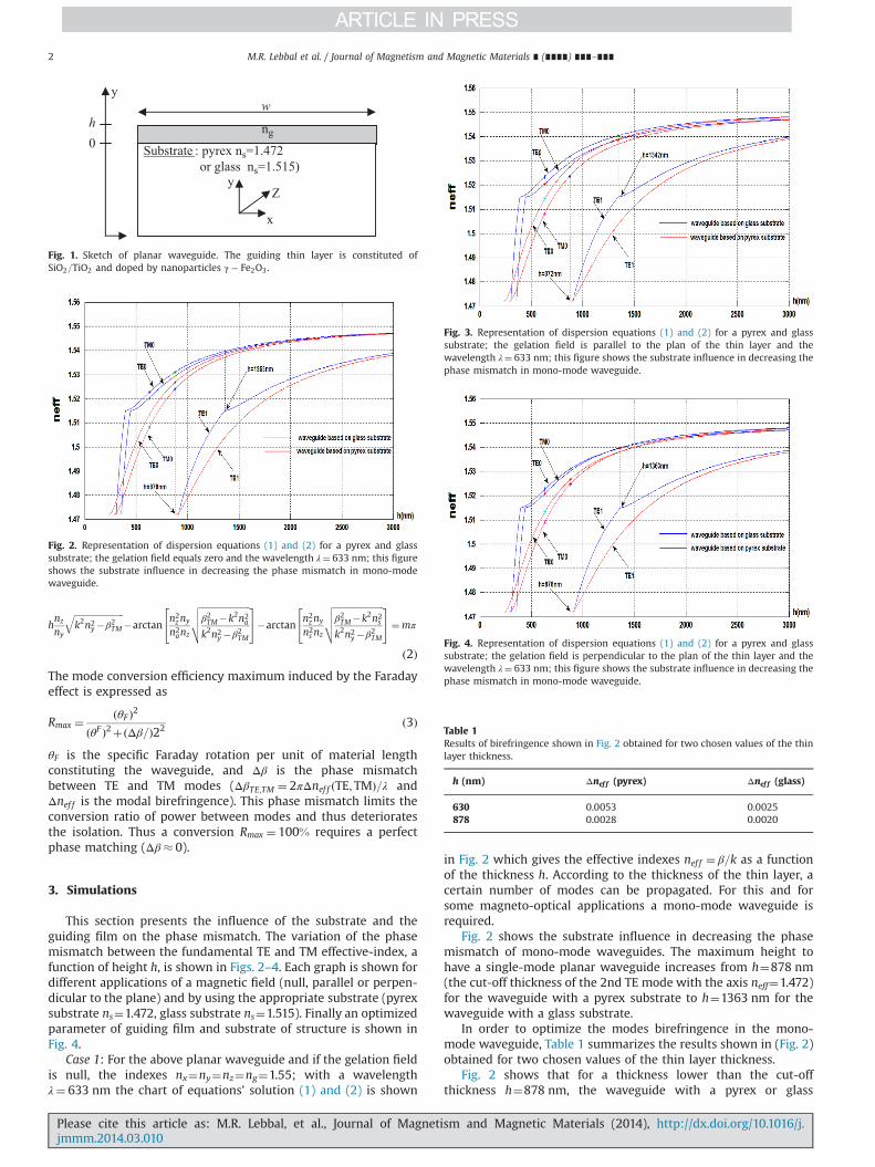
This section presents the influence of the substrate and theguiding film on the phase mismatch. The variation of the phasemismatch between the fundamental TE and TM effective-index, afunction of height h, is shown in Figs. 2–4. Each graph is shown fordifferent applications of a magnetic field (null, parallel or perpen-dicular to the plane) and by using the appropriate substrate (pyrexsubstrate ns¼1.472, glass substrate ns¼1.515). Finally an optimizedparameter of guiding film and substrate of structure is shown inFig. 4.
Case 1: For the above planar waveguide and if the gelation fieldis null, the indexes nx¼ny¼nz¼ng¼1.55; with a wavelengthλ¼ 633 nm the chart of equations' solution (1) and (2) is shown
in Fig. 2 which gives the effective indexes nef f ¼ β=k as a functionof the thickness h. According to the thickness of the thin layer, acertain number of modes can be propagated. For this and forsome magneto-optical applications a mono-mode waveguide isrequired.
Fig. 2 shows the substrate influence in decreasing the phasemismatch of mono-mode waveguides. The maximum height tohave a single-mode planar waveguide increases from h¼878 nm(the cut-off thickness of the 2nd TE mode with the axis neff¼1.472)for the waveguide with a pyrex substrate to h¼1363 nm for thewaveguide with a glass substrate.
In order to optimize the modes birefringence in the mono-mode waveguide, Table 1 summarizes the results shown in (Fig. 2)obtained for two chosen values of the thin layer thickness.
Fig. 2 shows that for a thickness lower than the cut-offthickness h¼878 nm, the waveguide with a pyrex or glass
y
Substrate : pyrex ns=1.472 or glass ns=1.515)
h w
x
y Z
0 ng
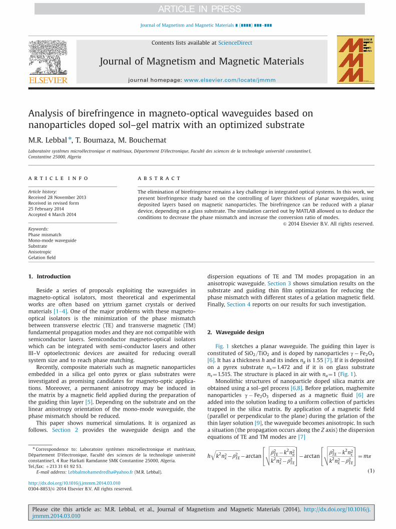
Fig. 1. Sketch of planar waveguide. The guiding thin layer is constituted ofSiO2=TiO2 and doped by nanoparticles γ� Fe2O3.
Fig. 2. Representation of dispersion equations (1) and (2) for a pyrex and glasssubstrate; the gelation field equals zero and the wavelength λ¼ 633 nm; this figureshows the substrate influence in decreasing the phase mismatch in mono-modewaveguide.
Fig. 3. Representation of dispersion equations (1) and (2) for a pyrex and glasssubstrate; the gelation field is parallel to the plan of the thin layer and thewavelength λ¼ 633 nm; this figure shows the substrate influence in decreasing thephase mismatch in mono-mode waveguide.
Fig. 4. Representation of dispersion equations (1) and (2) for a pyrex and glasssubstrate; the gelation field is perpendicular to the plan of the thin layer and thewavelength λ¼ 633 nm; this figure shows the substrate influence in decreasing thephase mismatch in mono-mode waveguide.
Table 1Results of birefringence shown in Fig. 2 obtained for two chosen values of the thinlayer thickness.
h (nm) Δnef f (pyrex) Δnef f (glass)
630 0.0053 0.0025878 0.0028 0.0020
M.R. Lebbal et al. / Journal of Magnetism and Magnetic Materials ∎ (∎∎∎∎) ∎∎∎–∎∎∎2
Please cite this article as: M.R. Lebbal, et al., Journal of Magnetism and Magnetic Materials (2014), http://dx.doi.org/10.1016/j.jmmm.2014.03.010i
substrate is mono-mode. It also shows that the birefringencedecreases when the height h increases and the best substratewith the lowest birefringence is based on glass. The optimal valueof birefringence for the pyrex substrate Δnef f ðpyrexÞ ¼ 0:0028 canbe improved to Δnef f ðglassÞ ¼ 0:0020. In addition, the glass sub-strate can lead to an increase of the cut thickness value of the 2ndTE mode to h¼1363 nm with a birefringence Δnef f ðglassÞ ¼ 0:0010lower than that of the pyrex substrate; thus the glass substratecontributes to increasing the thickness range, guaranteeing themono-mode waveguide character and decreasing the phase mis-match (the thickness is taken lower than and close to the thicknessof the cut-off of the 2nd mode TE).
Case 2: When the gelation field is applied parallel to the thinlayer, this means that nx≻ ny;nz
� �and the waveguide is anisotropic:
nx¼1.551 and ny¼nz¼1.55. Representation of the dispersionequations (1) and (2) is shown in Fig. 3.
Fig. 3 shows the variation of the TE–TM fundamental modeeffective-index as a function of height h. In this case the linearanisotropy in the direction x has a large influence on birefringenceand the mono-mode waveguide because the TE effective indexesbecome higher than those of TM modes. We can notice that thedistance between TE–TM fundamental mode curves (birefrin-gence) variation is larger in Fig. 3 than the distance between themin Fig. 2.
We also notice, as in the case of a null gelation field (Fig. 2) thatthe best performance for the different values of thickness isobserved for the guiding layers deposited on glass substrate withheight lesser than but close to the cut-off thickness of the 2nd TEmode [10]. This cut-off h¼1342 nm corresponds to Δnef f ¼ 0:0015,which is worse than in case 1 (Fig. 2).
Tables 2 and 3 show, for comparison, values of the cut offthickness with glass and pyrex substrates. In case 2, we can remarkthat the cut-off thickness value of the 2nd TE mode (for a pyrex orglass substrate) is lower than in case 1; thus, this contributes tothe increase of the phase mismatch for the cut off thickness of thepyrex, with the optimal substrate (glass) from Δnef f ¼ 0:0020 forcase 1 in Fig. 2 to Δnef f ¼ 0:0025 for case 2 in Fig. 3. So, this effect isundesirable compared to case 1 because its disruption reduces theconversion efficiency between the modes, leading to ellipticalpolarization, and seriously degrades the performance of theisolators by causing light to leak through into the source. However,in order to optimize the birefringence, we must decrease the TEfundamental mode effective-index and select glass substrate as weare going to see in case 3.
Case 3: The field is now applied perpendicular to the plane ofthe thin layer; it means that ny≻ nx;nzð Þ and the waveguide isanisotropic: ny¼1.551, nx¼nz¼1.55. Representation of the disper-sion equations is shown in Fig. 4.
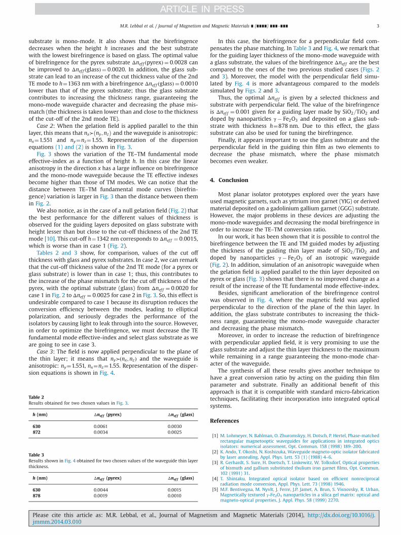
In this case, the birefringence for a perpendicular field com-pensates the phase matching. In Table 3 and Fig. 4, we remark thatfor the guiding layer thickness of the mono-mode waveguide witha glass substrate, the values of the birefringence Δnef f are the bestcompared to the ones of the two previous studied cases (Figs. 2and 3). Moreover, the model with the perpendicular field simu-lated by Fig. 4 is more advantageous compared to the modelssimulated by Figs. 2 and 3.
Thus, the optimal Δnef f is given by a selected thickness andsubstrate with perpendicular field. The value of the birefringenceis Δnef f ¼ 0:001 given for a guiding layer made by SiO2=TiO2 anddoped by nanoparticles γ� Fe2O3 and deposited on a glass sub-strate with thickness h¼878 nm. Due to this effect, the glasssubstrate can also be used for tuning the birefringence.
Finally, it appears important to use the glass substrate and theperpendicular field in the guiding thin film as two elements todecrease the phase mismatch, where the phase mismatchbecomes even weaker.
4. Conclusion
Most planar isolator prototypes explored over the years haveused magnetic garnets, such as yttrium iron garnet (YIG) or derivedmaterial deposited on a gadolinium gallium garnet (GGG) substrate.However, the major problems in these devices are adjusting themono-mode waveguides and decreasing the modal birefringence inorder to increase the TE–TM conversion ratio.
In our work, it has been shown that it is possible to control thebirefringence between the TE and TM guided modes by adjustingthe thickness of the guiding thin layer made of SiO2=TiO2 anddoped by nanoparticles γ� Fe2O3 of an isotropic waveguide(Fig. 2). In addition, simulation of an anisotropic waveguide whenthe gelation field is applied parallel to the thin layer deposited onpyrex or glass (Fig. 3) shows that there is no improved change as aresult of the increase of the TE fundamental mode effective-index.
Besides, significant amelioration of the birefringence controlwas observed in Fig. 4, where the magnetic field was appliedperpendicular to the direction of the plane of the thin layer. Inaddition, the glass substrate contributes to increasing the thick-ness range, guaranteeing the mono-mode waveguide characterand decreasing the phase mismatch.
Moreover, in order to increase the reduction of birefringencewith perpendicular applied field, it is very promising to use theglass substrate and adjust the thin layer thickness to the maximumwhile remaining in a range guaranteeing the mono-mode char-acter of the waveguide.
The synthesis of all these results gives another technique tohave a great conversion ratio by acting on the guiding thin filmparameter and substrate. Finally an additional benefit of thisapproach is that it is compatible with standard micro-fabricationtechniques, facilitating their incorporation into integrated opticalsystems.
References
[1] M. Lohmeyer, N. Bahlman, O. Zhuromskyy, H. Dotsch, P. Hertel, Phase-matchedrectangular magnetooptic waveguides for applications in integrated opticsisolators: numerical assessment, Opt. Commun. 158 (1998) 189–200.
[2] K. Ando, T. Okoshi, N. Koshizuka, Waveguide magneto-optic isolator fabricatedby laser annealing, Appl. Phys. Lett. 53 (1) (1988) 4–6.
[3] R. Gerhardt, S. Sure, H. Doetsch, T. Linkewitz, W. Tolksdorf, Optical propertiesof bismuth and gallium substituted thulium iron garnet films, Opt. Commun.102 (1991) 31.
[4] T. Shintaku, Integrated optical isolator based on efficient nonreciprocalradiation mode conversion, Appl. Phys. Lett. 73 (1998) 1946.
[5] M.F. Bentivegna, M. Nyvlt, J. Ferre, J.P. Jamet, A. Brun, S. Visnovsky, R. Urban,Magnetically textured γ-Fe2O3 nanoparticles in a silica gel matrix: optical andmagneto-optical properties, J. Appl. Phys. 58 (1999) 2270.
Table 2Results obtained for two chosen values in Fig. 3.
h (nm) Δnef f (pyrex) Δnef f (glass)
630 0.0061 0.0030872 0.0034 0.0025
Table 3Results shown in Fig. 4 obtained for two chosen values of the waveguide thin layerthickness.
h (nm) Δnef f (pyrex) Δnef f (glass)
630 0.0044 0.0015878 0.0019 0.0010
M.R. Lebbal et al. / Journal of Magnetism and Magnetic Materials ∎ (∎∎∎∎) ∎∎∎–∎∎∎ 3
Please cite this article as: M.R. Lebbal, et al., Journal of Magnetism and Magnetic Materials (2014), http://dx.doi.org/10.1016/j.jmmm.2014.03.010i
[6] D. Jamon, S. Robert, F. Donatini, J.J. Rousseau, C. Bovier, H. Roux, J. Serrughetti,V. Cabuil, D. Zins, Optical investigation of γ-Fe2O3 nanoparticles-doped silicagel matrix birefringent component, IEEE Trans. Magn. 37 (2001) 3803.
[7] François Royer, Etude et application des effets magnéto-optiques dans descouches minces sol–gel dopées à l’aide de nanoparticules magnétiques (Thèsepour obtenir le grade de docteur de L’INPG), France, 2004.
[8] C.J. Brinker, A.J. Hurd, P.R. Schunk, G.C. Frye, C.S. Ashley, Review of sol–gel thinfilm formation, J. Non-Cryst. Solids 147–148 (1992) 424–436.
[9] M.R. Lebbal, T. Boumaza, M. Bouchemat, A. Hocini, F. Hobar, A. Benghalia,J.J. Rosseau, F. Royer, Anisotropy adjustment and thickness of thin layer dopedby nanoparticules magnetic for the realization of phase matching betweenfundamental modes in monomodes waveguides, Eur. J. Appl. Phys. 42 (2008)75–80.
[10] M.R. Lebbal, T. Boumaza, M. Bouchemat, J.J. Rosseau, F. Royer, Birefringencecontrol in planar mono-mode waveguides using optimization of magneticsolution thin film and substrate, Int. Rev. Model. Simul. 5 (1) (2012) 477–481.
M.R. Lebbal et al. / Journal of Magnetism and Magnetic Materials ∎ (∎∎∎∎) ∎∎∎–∎∎∎4
Please cite this article as: M.R. Lebbal, et al., Journal of Magnetism and Magnetic Materials (2014), http://dx.doi.org/10.1016/j.jmmm.2014.03.010i
![Noise in distributed Raman amplification [6781-40] · amplification over length of several tens of km which is significantly larger than the distribution length of Erbium Doped Fiber](https://img.pdfslide.fr/doc/110x75/5faede2454006b677403579e/noise-in-distributed-raman-amplification-6781-40-amplification-over-length-of.jpg)


![Structure and electrical properties of Eu-doped SrBi ceramics 45 09.pdf · M. Afqir et al. /Processing and Applicationof Ceramics 13 [3] (2019)281–286 Figure 6. Temperature dependence](https://img.pdfslide.fr/doc/110x75/5e4c4a685d9d5115175c987a/structure-and-electrical-properties-of-eu-doped-srbi-45-09pdf-m-afqir-et-al.jpg)