Embed Size (px)
Citation preview
Crystallographic Determination of the Positions of the Copper Cations in Zeolite MFI
Bernard F. Mentzen*RZHGC, 5 rue Marcel Desplaces, F-69330 Meyzieu, France
Gerard BergeretIRCELYON (Institut de Recherches sur la Catalyse et l’EnVironnement de Lyon),UMR 5256 CNRS-UniVersiteLyon 1, 2 aVenue Albert-Einstein, F-69626 Villeurbanne Cedex, France
ReceiVed: July 12, 2007; In Final Form: July 20, 2007
Copper-exchanged Cu-MFI (Cu-ZSM-5) materials have been prepared by reacting H-MFI samples with0.1 M Cu(II) acetate solutions. Interpretation (Rietveld method) of X-ray powder diffraction (XRPD) profilescorresponding to two fully dehydrated Cu-MFI phases, reveals the presence of several independent extraframework Cu centers. In H1.04Cu(I)1.19Cu(II)0.51MFI and H1.99Cu(I)2.37Cu(II)0.00MFI, four and five Cu cationsare located, respectively. In these two phases, the Cu1/Cu2/Cu2′/Cu3/Cu3′ populations are 0.0/1.07/0.02/0.17/0.45 and 0.18/1.12/0.44/0.20/0.50 per unit cell (uc), respectively. Cu2 is the most populated one. Theshortest distances between copper sites and framework oxygen atoms involve the Cu1, Cu2, and Cu2′ sites(Cu-O in the 1.99-2.32 Å range). The Cu1, Cu3, and Cu3′ sites are trapped in secondary five and six ringchannel sections of the MFI framework. Cu2 and Cu2′ are very close to the 10-membered rings of the straightchannel sections. One or both of these cations, which are immediately accessible to guest molecules, appearto be the prime candidates for the catalytically active sites in copper-exchanged MFI.
1. Introduction
Since the pioneering work of Iwamoto’s group on the specificcatalytic activity of copper-exchanged MFI-type zeolitic nano-structured materials1 concerning the selective decomposition ofNO and NOx into molecular oxygen and nitrogen,2-7 extensiveexperimental [e.g., DRIFTS, XRD, XAS, INS (inelastic neutronscattering), EDA (energy dispersive analysis), XPS, IR andFTIR, UV-vis, NMR, EPR, ESR, EXAFS, XANES, thermo-chemistry (TG, DTA, DTG), CVD (chemical vapor transport),calorimetry, and adsorption isotherms] and theoretical [DFT,LSDFT (low-spin DFT), molecular modeling, quantum mechan-ics, and interatomic potential functions] work has been devotedto determine the nature and locations of active Cu sites8-26 (andmany refs therein). Presently, to the best of our knowledge, nounambiguous locations of active copper centers in Cu-MFIhave yet been determined by crystal-chemical investigations.At this date, most of the proposed Cu sites are derived fromtheoretical work. Given the specific influence of charge-compensating cations on the structural, adsorptive, diffusive,and catalytic properties of MFI-type materials, a preciseknowledge of their locations is of paramount importance for abetter understanding of the physicochemical reactions involvedat the microscopic level in many industrial processes. Comparedto faujasite-type zeolitic materials (X- and Y-type FAU),1 forwhich many cation locations are known (e.g., monovalentalkaline, divalent alkaline earth, Ag+, Tl+, Mg2+, Cd2+, Mn2+,La3+, In (several Inn+ valence states and Inx cationic clusters),very little information concerning such locations in cation-exchanged MFI-type phases are known.27 The first workreporting unambiguous cation locations in an MFI zeolite (using
X-ray powder diffraction) concerns a fully dehydrated cesium-exchanged phase.28 Four independent Li+ cation locations couldbe characterized in an as-synthesized [TPA4Li8(Li 4Si92O192)]lithosilicate (twinned-crystal structure determination) presentingthe MFI-type framework structure,1,29 containing the TPA+
(tetrapropylammonium ion) template and Li species in bothcationic and framework T (Si) sites. Recently, in the scope ofa general research on zeolitic host-guest complexes, thelocations of Cs cations and water molecules have beendetermined (in situ and ex situ X-ray diffraction on powderedsamples) at several temperatures, in both dehydrated30 andhydrated31,32 Csx-MFI‚nH2O zeolitic phases (0.7< x < 7.7and 0< n < 28). By using the methodology described in refs30-32, it is shown in the following sections that it is possible
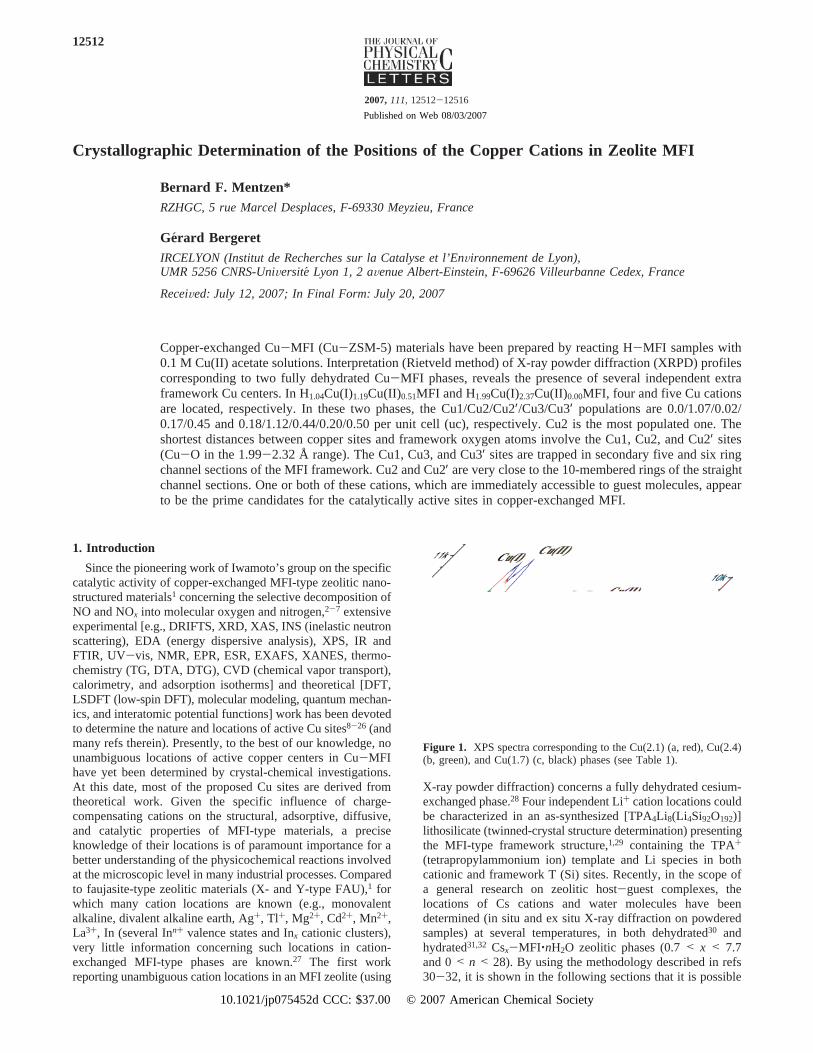
Figure 1. XPS spectra corresponding to the Cu(2.1) (a, red), Cu(2.4)(b, green), and Cu(1.7) (c, black) phases (see Table 1).
12512
2007,111,12512-12516
Published on Web 08/03/2007
10.1021/jp075452d CCC: $37.00 © 2007 American Chemical Society
to characterize several cationic centers in Cu-exchanged MFIphases. Complete description of the MFI framework structureand channel system is given below (section 4).
2. Experimental Section
2.1. Materials.Cu-exchanged MFI-type phases are obtainedby reacting (three 1 day batches, with periodic shaking) atseveral temperatures (25-75 °C range) two H-MFI parentmaterials in 0.1 M copper(II) acetate solutions. After filtering,washing (deionized water), and drying (at ambient temperature),four Cu-MFI phases are analyzed by chemical methods andX-ray photoelectron spectroscopy (XPS), and their chemicalformulations (H, Al, Si, Cu(I), and Cu(II) contents), Cu/uc andCu/Al ratios, and reaction temperatures are given inTable 1. The 28.5 and 21 Si/Al ratios (in brackets) correspondto H-form zeolites from Conteka (alkaline medium) andMulhouse (Laboratoire des Mate´riaux a PorositeControllee,UMR CNRS 7016, Universite´ de Haute-Alsace, France; fluoridemedium), respectively. These parent materials were alreadyreported in ref 30. The pH of the solutions are not adjusted(pH ≈ 6.2).
2.2. Experimental Methods. X-ray powder diffractiondata are collected at the SNBL (Swiss-Norwegian BeamLines, Grenoble, France, BM01B line, synchrotron radiationλ) 0.50013 Å). The samples are packed into 0.7 mm (innerdiameter) borosilicate capillaries and heated at 450°C beforesealing. It has been verified by thermogravimetry that after thefirst heating (5°C/min)/cooling cycle (25< T < 450°C range),the investigated phases are fully dehydrated. The structurerefinements are performed using the Rietveld method (a locallymodified DBW3.2 code33 and the EXPGUI version of GSAS34).The XPS spectra are recorded at the IRCELYON on a KRATOSAXIS Ultra DLD spectrometer.
3. Crystallographic Results
The XPS spectra corresponding to three of the Cu-exchangedCu-MFI phases are represented in Figure 1. The characteristicCu(2p)3/2 peaks corresponding to the Cu(II) and Cu(I) species35
are present for both the Cu(1.7) and Cu(2.1) phases, whereassample Cu(2.4) contains only Cu(I) cations (Table 1). The datareported in Table 1 show that the Cu(I)/Cu(II) and Cu/Al ratiosand the residual proton concentrations are strongly influencedby the exchange temperature; a temperature increase lowers theCu(I)/Cu(II) ratio, enhances the copper over exchange (for Cu/Al > 0.5), and lowers the proton content in the final Cu-MFIphases. The collected XRPD profiles are interpreted by theRietveld method.33,34We report hereafter the crystal structuresof samples Cu(2.4) and Cu(1.7). For both Cu-MFI materials,the framework symmetry corresponds to the orthorhombicPnmaspace group, and the starting Si/O atomic positional parametersand the refinement process are those reported in refs 30-32.After refining the MFI framework Si,O atomic positions,subsequent difference Fourier maps show the presence of fourand five extra framework electronic residuals in Cu(1.7) andCu(2.4), respectively. These residuals are attributed to Cuspecies. Their locations are very close to framework oxygen
atoms, and after refinement of their atomic parameters, someof them contribute to very short Cu-O bonds. These bonds arerestrained to Cu-O ) 2.0 Å,36 and the structure is furtherrefined until complete convergence is achieved. The total Cu/uc populations are constrained to their chemical compositions.The final atomic positional parameters for Cu(1.7) and Cu(2.4)are given in Tables 1S and 2S as Supporting Information,respectively. Results corresponding to dehydrated and hydratedCu-MFI materials investigated under different experimentalconditions are reported elsewhere.37 The refined unit cellparameters for phases Cu(2.4) and Cu(1.7) at room temperature(25 °C) area ) 20.1084(2),b ) 19.9366(2),c ) 13.4072(1)Å, V ) 5375 Å3, anda ) 20.1049(3),b ) 19.9222(3),c )13.3936(3) Å,V ) 5364 Å3, respectively. The atomic positionalparameters of the Cu species in Cu(2.4) and Cu(1.7) are reportedin Table 2. Some selected Cu-O, Cu-Si, and Cu‚‚‚Cu distancesin phase Cu(2.4) are reported in Table 3. The locations of theCu sites characterized in this phase are represented in Figure 2.The Cu1 copper cation is absent in phase Cu(1.7). The Rietveldplots for Cu(2.4) are shown in Figure 3.
TABLE 1: Cu-Exchanged MFI Phases (Using H-MFI Materials Exchanged in 0.1 M Copper Acetate Solutions)
chemical composition total Cu/uc Cu(I)/Cu(II) Cu/Al T (°C) label
H1.99Cu(I)2.37Cu(II)0.00MFI[21]a 2.37 >100 0.54 25 Cu(2.4)H1.04Cu(I)1.19Cu(II)0.51MFI[28.5] 1.70 2.33 0.52 40 Cu(1.7)H0.00Cu(I)1.45Cu(II)1.45MFI[21] 2.90 1.00 0.67 60 Cu(2.9)H0.00Cu(I)0.93Cu(II)1.16MFI[28.5] 2.09 0.80 0.64 75 Cu(2.1)
a The Si/Al ratio is given in brackets.
TABLE 2: Locations of Cu Species in Cu-MFI PhasesCu(1.7) and Cu(2.4)
Chemical Compositionsite x y z popa
Cu(1.7): H1.04Cu(I)1.19Cu(II)0.51MFICu1 0.00Cu2 0.0331(9) 0.1346(8) 0.803(2) 1.07(5)Cu2′ 0.194(1) 0.0524(7) 0.483(1) 0.02(2)Cu3 0.1942(7) 0.25b 1.071(3) 0.17(3)Cu3′ 0.306(1) 0.25 0.709(2) 0.45(3)
Cu(2.4): H1.99Cu(I)2.37Cu(II)0.00MFICu1 -0.019(1) 0.25 1.038(2) 0.18(3)Cu2 0.030(1) 0.139(1) 0.800(2) 1.12(4)Cu2′ 0.194(6) 0.0549(8) 0.480(1) 0.44(4)Cu3 0.193(1) 0.25 1.067(4) 0.20(4)Cu3′ 0.304(2) 0.25 0.718(2) 0.50(4)
a Population in Cu/uc.b Fixed on them mirror plane ofPnma.
TABLE 3: Selected Cu-O, Cu-Si, and Cu‚‚‚Cu (Å)Distances In Phase Cu(2.4); Cu-O < 3.00(3) Å
atom pair distance atom pair distance
Cu1-O10 2.25(3)× 2 Cu2′-Si2 2.78(3)Cu1-O23 2.24(3) Cu2′-Si3 2.55(2)Cu1-O26 2.19(3) Cu2′-Si6 2.63(3)
Cu2′-Si8 2.59(3)Cu1-Si10 2.71(2)× 2 Cu2′-Si9 2.57(2)
Cu2-O4 2.56(3) Cu3-O17 2.97(3)× 2Cu2-O5 2.50(3) Cu3-O20 3.03(3)× 2Cu2-O15 2.53(3) Cu3-O23 2.69(3)Cu2-O21 1.99(3) Cu3-O24 2.63(3)
Cu2-Si1 2.72(2) Cu3′-O25 2.74(3)Cu2-Si5 2.33(2) Cu3′-O26 2.76(3)
Cu2′-O2 2.33(3) Cu1‚‚‚Cu2 4.00(4)× 2Cu2′-O8 2.14(3) Cu1‚‚‚Cu3 4.28(3)Cu2′-O13 2.23(4) Cu1‚‚‚Cu3′ 4.94(4)Cu2′-O18 2.32(3)Cu2′-O19 2.02(3) Cu2‚‚‚Cu2 4.43(3)
Letters J. Phys. Chem. C, Vol. 111, No. 34, 200712513
4. Discussion
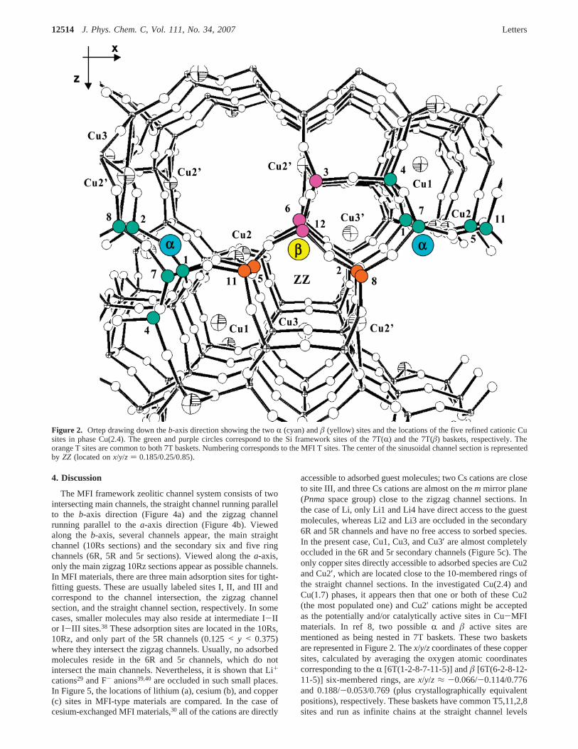
The MFI framework zeolitic channel system consists of twointersecting main channels, the straight channel running parallelto the b-axis direction (Figure 4a) and the zigzag channelrunning parallel to thea-axis direction (Figure 4b). Viewedalong theb-axis, several channels appear, the main straightchannel (10Rs sections) and the secondary six and five ringchannels (6R, 5R and 5r sections). Viewed along thea-axis,only the main zigzag 10Rz sections appear as possible channels.In MFI materials, there are three main adsorption sites for tight-fitting guests. These are usually labeled sites I, II, and III andcorrespond to the channel intersection, the zigzag channelsection, and the straight channel section, respectively. In somecases, smaller molecules may also reside at intermediate I-IIor I-III sites.38 These adsorption sites are located in the 10Rs,10Rz, and only part of the 5R channels (0.125< y < 0.375)where they intersect the zigzag channels. Usually, no adsorbedmolecules reside in the 6R and 5r channels, which do notintersect the main channels. Nevertheless, it is shown that Li+
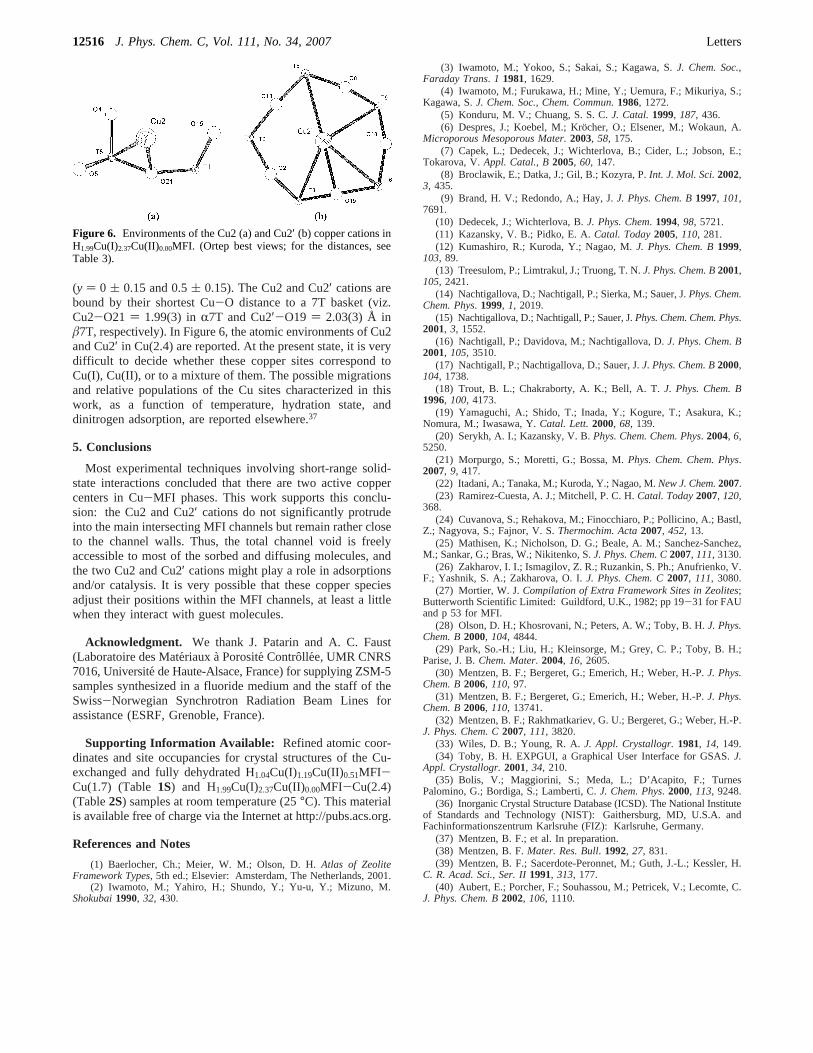
cations29 and F- anions39,40 are occluded in such small places.In Figure 5, the locations of lithium (a), cesium (b), and copper(c) sites in MFI-type materials are compared. In the case ofcesium-exchanged MFI materials,30 all of the cations are directly
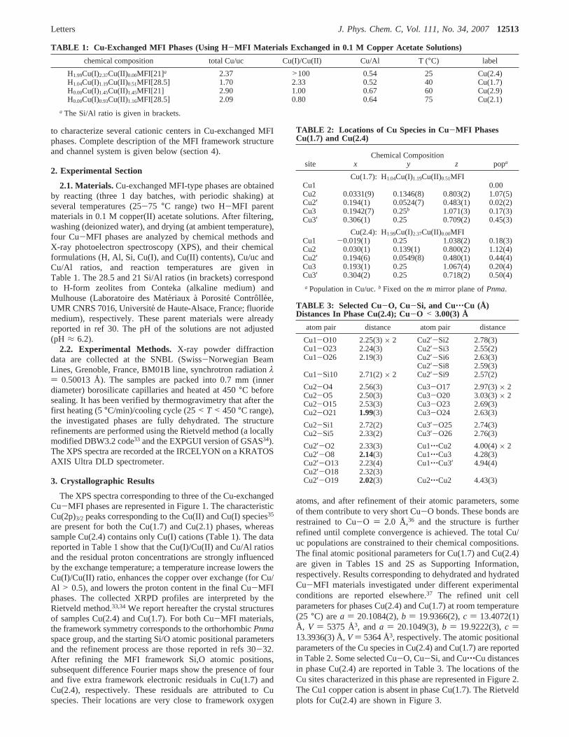
accessible to adsorbed guest molecules; two Cs cations are closeto site III, and three Cs cations are almost on themmirror plane(Pnmaspace group) close to the zigzag channel sections. Inthe case of Li, only Li1 and Li4 have direct access to the guestmolecules, whereas Li2 and Li3 are occluded in the secondary6R and 5R channels and have no free access to sorbed species.In the present case, Cu1, Cu3, and Cu3′ are almost completelyoccluded in the 6R and 5r secondary channels (Figure 5c). Theonly copper sites directly accessible to adsorbed species are Cu2and Cu2′, which are located close to the 10-membered rings ofthe straight channel sections. In the investigated Cu(2.4) andCu(1.7) phases, it appears then that one or both of these Cu2(the most populated one) and Cu2′ cations might be acceptedas the potentially and/or catalytically active sites in Cu-MFImaterials. In ref 8, two possibleR and â active sites arementioned as being nested in 7T baskets. These two basketsare represented in Figure 2. Thex/y/zcoordinates of these coppersites, calculated by averaging the oxygen atomic coordinatescorresponding to theR [6T(1-2-8-7-11-5)] andâ [6T(6-2-8-12-11-5)] six-membered rings, arex/y/z ≈ -0.066/-0.114/0.776and 0.188/-0.053/0.769 (plus crystallographically equivalentpositions), respectively. These baskets have common T5,11,2,8sites and run as infinite chains at the straight channel levels
Figure 2. Ortep drawing down theb-axis direction showing the twoR (cyan) andâ (yellow) sites and the locations of the five refined cationic Cusites in phase Cu(2.4). The green and purple circles correspond to the Si framework sites of the 7T(R) and the 7T(â) baskets, respectively. Theorange T sites are common to both 7T baskets. Numbering corresponds to the MFI T sites. The center of the sinusoidal channel section is representedby ZZ (located onx/y/z ) 0.185/0.25/0.85).
12514 J. Phys. Chem. C, Vol. 111, No. 34, 2007 Letters
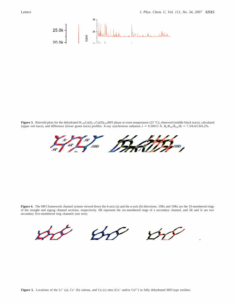
Figure 4. The MFI framework channel system viewed down theb-axis (a) and thea-axis (b) directions. 10Rs and 10Rz are the 10-membered ringsof the straight and zigzag channel sections, respectively. 6R represent the six-membered rings of a secondary channel, and 5R and 5r are twosecondary five-membered ring channels (see text).
Figure 5. Locations of the Li+ (a), Cs+ (b) cations, and Cu (c) sites (Cu+ and/or Cu2+) in fully dehydrated MFI-type zeolites.
Figure 3. Rietveld plots for the dehydrated H1.99Cu(I)2.37Cu(II)0.00MFI phase at room temperature (25°C); observed (middle black trace), calculated(upper red trace), and difference (lower green trace) profiles. X-ray synchrotron radiationλ ) 0.50013 Å.Rp/Rwp/Rexp/RI ) 7.3/8.4/5.8/6.2%.
Letters J. Phys. Chem. C, Vol. 111, No. 34, 200712515
(y ) 0 ( 0.15 and 0.5( 0.15). The Cu2 and Cu2′ cations arebound by their shortest Cu-O distance to a 7T basket (viz.Cu2-O21 ) 1.99(3) inR7T and Cu2′-O19 ) 2.03(3) Å inâ7T, respectively). In Figure 6, the atomic environments of Cu2and Cu2′ in Cu(2.4) are reported. At the present state, it is verydifficult to decide whether these copper sites correspond toCu(I), Cu(II), or to a mixture of them. The possible migrationsand relative populations of the Cu sites characterized in thiswork, as a function of temperature, hydration state, anddinitrogen adsorption, are reported elsewhere.37
5. Conclusions
Most experimental techniques involving short-range solid-state interactions concluded that there are two active coppercenters in Cu-MFI phases. This work supports this conclu-sion: the Cu2 and Cu2′ cations do not significantly protrudeinto the main intersecting MFI channels but remain rather closeto the channel walls. Thus, the total channel void is freelyaccessible to most of the sorbed and diffusing molecules, andthe two Cu2 and Cu2′ cations might play a role in adsorptionsand/or catalysis. It is very possible that these copper speciesadjust their positions within the MFI channels, at least a littlewhen they interact with guest molecules.
Acknowledgment. We thank J. Patarin and A. C. Faust(Laboratoire des Mate´riaux aPorositeControllee, UMR CNRS7016, Universite´ de Haute-Alsace, France) for supplying ZSM-5samples synthesized in a fluoride medium and the staff of theSwiss-Norwegian Synchrotron Radiation Beam Lines forassistance (ESRF, Grenoble, France).
Supporting Information Available: Refined atomic coor-dinates and site occupancies for crystal structures of the Cu-exchanged and fully dehydrated H1.04Cu(I)1.19Cu(II)0.51MFI-Cu(1.7) (Table1S) and H1.99Cu(I)2.37Cu(II)0.00MFI-Cu(2.4)(Table2S) samples at room temperature (25°C). This materialis available free of charge via the Internet at http://pubs.acs.org.
References and Notes
(1) Baerlocher, Ch.; Meier, W. M.; Olson, D. H.Atlas of ZeoliteFramework Types, 5th ed.; Elsevier: Amsterdam, The Netherlands, 2001.
(2) Iwamoto, M.; Yahiro, H.; Shundo, Y.; Yu-u, Y.; Mizuno, M.Shokubai1990, 32, 430.
(3) Iwamoto, M.; Yokoo, S.; Sakai, S.; Kagawa, S.J. Chem. Soc.,Faraday Trans. 1 1981, 1629.
(4) Iwamoto, M.; Furukawa, H.; Mine, Y.; Uemura, F.; Mikuriya, S.;Kagawa, S.J. Chem. Soc., Chem. Commun.1986, 1272.
(5) Konduru, M. V.; Chuang, S. S. C.J. Catal.1999, 187, 436.(6) Despres, J.; Koebel, M.; Kro¨cher, O.; Elsener, M.; Wokaun, A.
Microporous Mesoporous Mater.2003, 58, 175.(7) Capek, L.; Dedecek, J.; Wichterlova, B.; Cider, L.; Jobson, E.;
Tokarova, V.Appl. Catal., B2005, 60, 147.(8) Broclawik, E.; Datka, J.; Gil, B.; Kozyra, P.Int. J. Mol. Sci.2002,
3, 435.(9) Brand, H. V.; Redondo, A.; Hay, J.J. Phys. Chem. B1997, 101,
7691.(10) Dedecek, J.; Wichterlova, B.J. Phys. Chem. 1994, 98, 5721.(11) Kazansky, V. B.; Pidko, E. A.Catal. Today2005, 110, 281.(12) Kumashiro, R.; Kuroda, Y.; Nagao, M.J. Phys. Chem. B1999,
103, 89.(13) Treesulom, P.; Limtrakul, J.; Truong, T. N.J. Phys. Chem. B2001,
105, 2421.(14) Nachtigallova, D.; Nachtigall, P.; Sierka, M.; Sauer, J.Phys. Chem.
Chem. Phys. 1999, 1, 2019.(15) Nachtigallova, D.; Nachtigall, P.; Sauer, J.Phys. Chem. Chem. Phys.
2001, 3, 1552.(16) Nachtigall, P.; Davidova, M.; Nachtigallova, D.J. Phys. Chem. B
2001, 105, 3510.(17) Nachtigall, P.; Nachtigallova, D.; Sauer, J.J. Phys. Chem. B2000,
104, 1738.(18) Trout, B. L.; Chakraborty, A. K.; Bell, A. T.J. Phys. Chem. B
1996, 100, 4173.(19) Yamaguchi, A.; Shido, T.; Inada, Y.; Kogure, T.; Asakura, K.;
Nomura, M.; Iwasawa, Y.Catal. Lett.2000, 68, 139.(20) Serykh, A. I.; Kazansky, V. B.Phys. Chem. Chem. Phys. 2004, 6,
5250.(21) Morpurgo, S.; Moretti, G.; Bossa, M.Phys. Chem. Chem. Phys.
2007, 9, 417.(22) Itadani, A.; Tanaka, M.; Kuroda, Y.; Nagao, M.New J. Chem.2007.(23) Ramirez-Cuesta, A. J.; Mitchell, P. C. H.Catal. Today2007, 120,
368.(24) Cuvanova, S.; Rehakova, M.; Finocchiaro, P.; Pollicino, A.; Bastl,
Z.; Nagyova, S.; Fajnor, V. S.Thermochim. Acta2007, 452, 13.(25) Mathisen, K.; Nicholson, D. G.; Beale, A. M.; Sanchez-Sanchez,
M.; Sankar, G.; Bras, W.; Nikitenko, S.J. Phys. Chem. C2007, 111, 3130.(26) Zakharov, I. I.; Ismagilov, Z. R.; Ruzankin, S. Ph.; Anufrienko, V.
F.; Yashnik, S. A.; Zakharova, O. I.J. Phys. Chem. C2007, 111, 3080.(27) Mortier, W. J.Compilation of Extra Framework Sites in Zeolites;
Butterworth Scientific Limited: Guildford, U.K., 1982; pp 19-31 for FAUand p 53 for MFI.
(28) Olson, D. H.; Khosrovani, N.; Peters, A. W.; Toby, B. H.J. Phys.Chem. B2000, 104, 4844.
(29) Park, So.-H.; Liu, H.; Kleinsorge, M.; Grey, C. P.; Toby, B. H.;Parise, J. B.Chem. Mater. 2004, 16, 2605.
(30) Mentzen, B. F.; Bergeret, G.; Emerich, H.; Weber, H.-P.J. Phys.Chem. B2006, 110, 97.
(31) Mentzen, B. F.; Bergeret, G.; Emerich, H.; Weber, H.-P.J. Phys.Chem. B2006, 110, 13741.
(32) Mentzen, B. F.; Rakhmatkariev, G. U.; Bergeret, G.; Weber, H.-P.J. Phys. Chem. C2007, 111, 3820.
(33) Wiles, D. B.; Young, R. A.J. Appl. Crystallogr.1981, 14, 149.(34) Toby, B. H. EXPGUI, a Graphical User Interface for GSAS.J.
Appl. Crystallogr.2001, 34, 210.(35) Bolis, V.; Maggiorini, S.; Meda, L.; D’Acapito, F.; Turnes
Palomino, G.; Bordiga, S.; Lamberti, C.J. Chem. Phys. 2000, 113, 9248.(36) Inorganic Crystal Structure Database (ICSD). The National Institute
of Standards and Technology (NIST): Gaithersburg, MD, U.S.A. andFachinformationszentrum Karlsruhe (FIZ): Karlsruhe, Germany.
(37) Mentzen, B. F.; et al. In preparation.(38) Mentzen, B. F.Mater. Res. Bull. 1992, 27, 831.(39) Mentzen, B. F.; Sacerdote-Peronnet, M.; Guth, J.-L.; Kessler, H.
C. R. Acad. Sci., Ser. II1991, 313, 177.(40) Aubert, E.; Porcher, F.; Souhassou, M.; Petricek, V.; Lecomte, C.
J. Phys. Chem. B2002, 106, 1110.
Figure 6. Environments of the Cu2 (a) and Cu2′ (b) copper cations inH1.99Cu(I)2.37Cu(II)0.00MFI. (Ortep best views; for the distances, seeTable 3).
12516 J. Phys. Chem. C, Vol. 111, No. 34, 2007 Letters