Embed Size (px)
Citation preview
METALS AND MATERIALS, Vol. 4, No. 3 (1998), pp. 252~255
Elastoplastic Analysis of Inclusion Reinforced Structures
Bruno Sudret, Samir Maghous Patrick de Buhan and Denise Bernaud
Laboratoire de Mrcanique des Solides (URA 317) Centre d'Enseignement et de Recherche en Calcul des Structures et des Ouvrages
ENPC 6 et 8 Av. Blaise Pascal, Cit6 Descartes 77455 Marne la Vallre Cedex 2, France
An analytical model for assessing the global elastoplastic behaviour of inclusion-reinforced materials is presented in this contribution. It is based upon a description of the reinforced material as a two-phase com- posite system, namely a matrix material and the reinforcements which are assumed to behave as tensile-com- pressive load carrying elements. An anisotropic elastoplastic constitutive law exhibiting work-hardening is then derived in an explicit form. It involves a number of hardening parameters equal to the number of rein- forcing directions. Such a model, which is readily implementable in a finite element computer code, is ap- plied to the numerical simulation of the settlement of a shallow strip footing resting upon a soil reinforced in two symmetric directions ("micropiling technique"). The load-settlement curve predicted from using the work-hardening model is finally compared with that deduced from a previously-adopted elastic perfectly plastic schematization of the reinforced soil.
Key words : plasticity, hardening, anisotropy, soil reinforcement, computer simulation
1. I N T R O D U C T I O N
In the area of soil or rock improvement, the rein- forcement by means of metallic inclusions has been widely developed under different forms (reinforced earth, soil nailing, rock bolting, ...). These inclusions are usu- ally disposed periodically in an homogeneous medium (matrix) so that it is possible to isolate a representative cell, whose properties describe entirely the whole struc- ture. Consequently, homogenization methods have been applied to deal with such materials.
The composite made of soil and inclusions is con- sidered at a macroscopic scale as an homogeneous medi- um, the mechanical properties of which are deduced from those of each constituent. In the elastic domain, Hashin [7] presents a review of the literature. Adopting a yield design point of view, de Buhan and Salenqon [2], de Buhan and Talercio [4] have derived the ultimate yield surface of the composite. By considering this sur- face as a perfect plasticity yield surface, Greuell et al. [5] has treated the problem of bolt-supported tunnels analyt- ically, and Bemaud et al. [1] have proposed a numerical implementation of this method.
In this contribution, we propose an alternative model of the reinforced medium and compare this approach
with that of Bemaud et al. [1] on the example of a foun- dation on reinforced soil.
2. C O N S T I T U T I V E A S S U M P T I O N S A N D B A S I C R E L A T I O N S H I P S
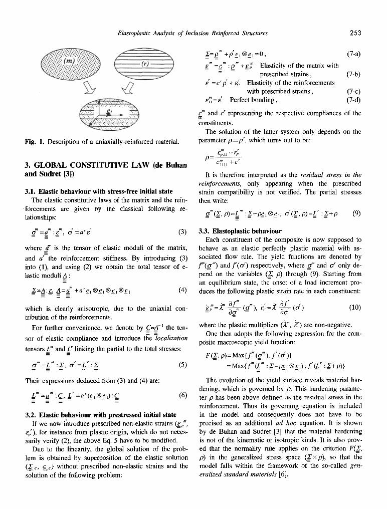
Consider a single array of inclusions periodically pla- ced parallel to a given direction characterized by a unit vector el (Fig. 1). At the macroscopic scale, the internal forces in the medium are represented by a total stress ten- sor __Xdecomposed into a matrix and a reinforcement con- tribution, so that:
Z = ~ + d e 1 | (1)
where _rf' is the partial stress in the matrix material, while the second term shows that the contribution of the reinforcing inclusions is purely uniaxial.
Assuming perfect bonding between matrix and in- clusions, the total strain tensor ~ can be identified to that of the matrix s The strain compatibility between the constituents writes then:
_~m ~ m =~_ and d ~ : ~ , | (2)
where __e" denotes the (linearized) strain in the matrix ma- terial, and gr the axial strain in the reinforcements.
Elastoplastic Analysis of Inclusion Reinforced Structures 253
Fig. 1. Description of a uniaxially-reinforced material.
3. GLOBAL CONSTITUTIVE LAW (de Buhan and Sudret [3])
3.1. Elastic behaviour with stress-free initial state The elastic constitutive laws of the matrix and the rein-
forcements are given by the classical following re- lationships:
(~ = a m :8 m, O "r = a r e (3)
where _d" is the tensor of elastic moduli of the matrix,
and a r the reinforcement stiffmess. By introducing (3) into (1), and using (2) we obtain the total tensor of e- lastic moduli A :
Z=A:e_, A=a" + a r e l O e l | (4)
which is clearly anisotropic, due to the uniaxial con- tribution of the reinforcements.
For further convenience, we denote by C=A ~ the ten-
sor of elastic compliance and introduce the localization
tensors_L m and_U linking the partial to the total stresses:
0 "m : Z m , g , { r = L r : .~ (5)
Their expressions deduced from (3) and (4) are:
L" =a" :C_, L' =a'(q_,Oe0:C_ (6)
3.2. Elastic behaviour with prestressed initial state If we now introduce prescribed non-elastic strains ~pm,
ep~), for instance from plastic origin, which do not neces- sarily verify (2), the above Eq. 5 have to be modified.
Due to the linearity, the global solution of the prob- lem is obtained by superposition of the elastic solution ( ~ , ~ ) without prescribed non-elastic strains and the solution of the following problem:
g=pm +je , | =0, (7-a) m m m m
__e =__c :p_ +__ep Elasticity of the matrix with - prescribed strains, (7-b)
d = c �9 + e~ Elasticity of the reinforcements with prescribed strains, (7-c)
el~ = e ~ Perfect bonding, (7-d)
c" and c r representing the respective compliances of the
~onstituents. The solution of the latter system only depends on the
parameter p=pr , which turns out to be:
,11 - - / ~ P p= C ~ l l l +C r
It is therefore interpreted as the residual stress in the reinforcements, only appearing when the prescribed strain compatibility is not verified. The partial stresses then write:
_ffm(_z,p)=L m :Z-ps174 d(__Z,p)=ff :Z+p (9)
3.3. Elastoplastic behaviour Each constituent of the composite is now supposed to
behave as an elastic perfectly plastic material with as- sociated flow role. The yield functions are denoted by
f r o ( | a n d f ( & ) respectively, where __~ and o "r only de- pend on the variables (~ p) through (9). Starting from an equilibrium state, the onset of a load increment pro- duces the following plastic strain rate in each constituent:
8p=)~ �9 m ' . r ' r a f = = af" = -~d~-(~_ _ ), e ~ = z T3-~ ( d ) ( lo)
where the plastic multipliers (,~", ,~r) are non-negative. One then adopts the following expression for the com-
posite macroscopic yield function:
F (_Z_, p)=Max{fm (ffm), f r (d)}
=Max{fm~ m :_Z-ps | f r ~ r :_Z+p)}
The evolution of the yield surface reveals material har- dening, which is governed by p. This hardening parame- ter p has been above defined as the residual stress in the reinforcement. Thus its governing equation is included in the model and consequently does not have to be precised as an additional ad hoc equation. It is shown by de Buhan and Sudret [3] that the material hardening is not of the kinematic or is| kinds. It is also prov- ed that the normality rule applies on the criterion F(__Z, p) in the generalized stress space (__27• so that the model falls within the framework of the so-called gen- eralized standard materials [6].
254 Bruno Sudret et al.
The above formalism has been developed for a single array of reinforcements, but can be easily generalized to any number N of directions. For instance Eq. 4 is ge- neralized by adding a uniaxial contribution in each direc- tion. Similarly the global yield criterion involves N har- dening parameters.
4. A P P L I C A T I O N T O A S I M P L E C A S E AND N U M E R I C A L I M P L E M E N T A T I O N
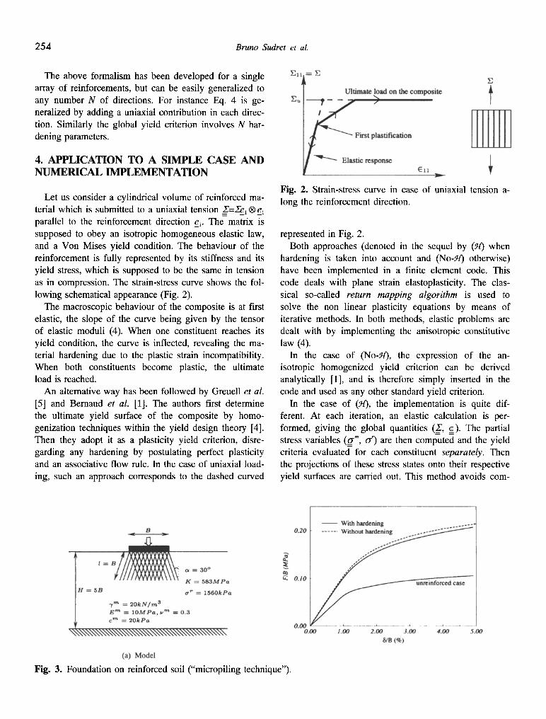
Let us consider a cylindrical volume of reinforced ma- terial which is submitted to a uniaxial tension _Z'=.Sel | e 1 parallel to the reinforcement direction el. The matrix is supposed to obey an isotropic homogeneous elastic law, and a Von Mises yield condition. The behaviour of the reinforcement is fully represented by its stiffness and its yield stress, which is supposed to be the same in tension as in compression. The strain-stress curve shows the fol- lowing schematical appearance (Fig. 2).
The macroscopic behaviour of the composite is at first elastic, the slope of the curve being given by the tensor of elastic moduli (4). When one constituent reaches its yield condition, the curve is inflected, revealing the ma- terial hardening due to the plastic strain incompatibility. When both constituents become plastic, the ultimate load is reached.
An alternative way has been followed by Greuell et al. [5] and Bernaud et al. [1]. The authors first determine the ultimate yield surface of the composite by homo- genization techniques within the yield design theory [4]. Then they adopt it as a plasticity yield criterion, disre- garding any hardening by postulating perfect plasticity and an associative flow rule. In the case of uniaxial load- ing, such an approach corresponds to the dashed curved
Fig. 2. Strain-stress curve in case of uniaxial tension a- long the reinforcement direction.
represented in Fig. 2. Both approaches (denoted in the sequel by (H) when
hardening is taken into account and (No-H) otherwise) have been implemented in a finite element code. This code deals with plane strain elastoplasticity. The clas- sical so-called return mapping algorithm is used to solve the non linear plasticity equations by means of iterative methods. In both methods, elastic problems are dealt with by implementing the anisotropic constitutive law (4).
In the case of (No-:if), the expression of the an- isotropic homogenized yield criterion can be derived analytically [1], and is therefore simply inserted in the code and used as any other standard yield criterion.
In the case of (~t), the implementation is quite dif- ferent. At each iteration, an elastic calculation is per- formed, giving the global quantities (_27, _~). The partial stress variables (__o-", or) are then computed and the yield criteria evaluated for each constituent separately. Then the projections of these stress states onto their respective yield surfaces are carried out. This method avoids com-
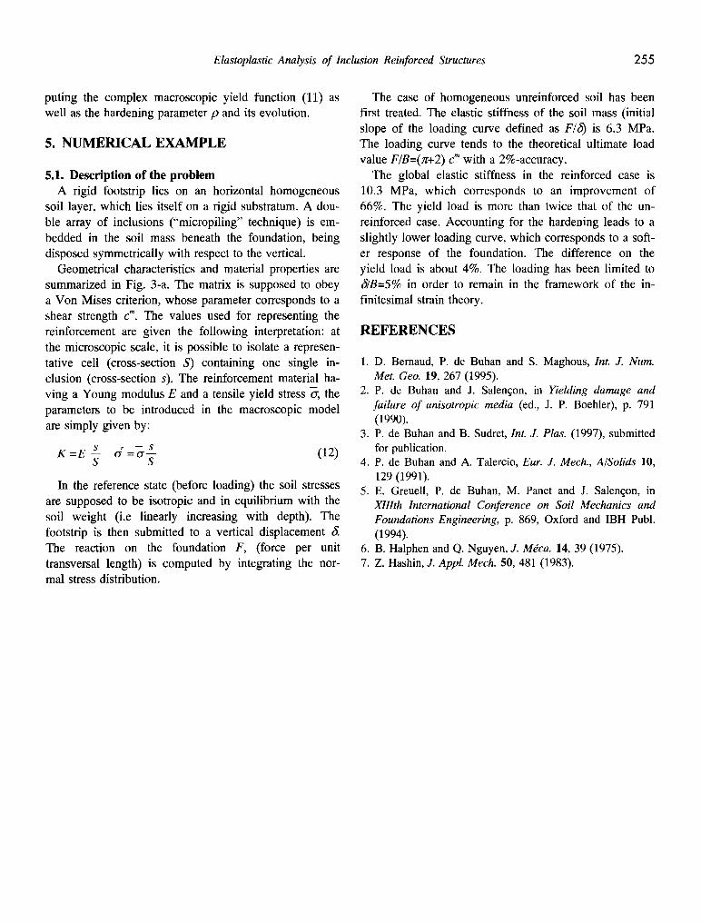
Fig. 3. Foundation on reinforced soil ("micropiling technique").
Elastoplastic Analysis of Inclusion Reinforced Structures 255
puting the complex macroscopic yield function (11) as well as the hardening parameter p and its evolution.
5. NUMERICAL EXAMPLE
5.1. Description of the problem A rigid footstrip lies on an horizontal homogeneous
soil layer, which lies itself on a rigid substratum. A dou- ble array of inclusions ("micropiling" technique) is em- bedded in the soil mass beneath the foundation, being disposed symmetrically with respect to the vertical.
Geometrical characteristics and material properties are summarized in Fig. 3-a. The matrix is supposed to obey a Von Mises criterion, whose parameter corresponds to a shear strength c m. The values used for representing the reinforcement are given the following interpretation: at the microscopic scale, it is possible to isolate a represen- tative cell (cross-section S) containing one single in- clusion (cross-section s). The reinforcement material ha- ving a Young modulus E and a tensile yield stress o-, the parameters to be introduced in the macroscopic model are simply given by:
K =E --s err =or--- s (12) S S
In the reference state (before loading) the soil stresses are supposed to be isotropic and in equilibrium with the soil weight (i.e linearly increasing with depth). The footstrip is then submitted to a vertical displacement ~. The reaction on the foundation F, (force per unit transversal length) is computed by integrating the nor- mal stress distribution.
The case of homogeneous unreinforced soil has been first treated. The elastic stiffness of the soil mass (initial slope of the loading curve defined as F/6) is 6.3 MPa. The loading curve tends to the theoretical ultimate load value F/B=(~r+2) c m with a 2%-accuracy.
The global elastic stiffness in the reinforced case is 10.3 MPa, which corresponds to an improvement of 66%. The yield load is more than twice that of the un- reinforced case. Accounting for the hardening leads to a slightly lower loading curve, which corresponds to a soft- er response of the foundation. The difference on the yield load is about 4%. The loading has been limited to ~B=5% in order to remain in the framework of the in- finitesimal strain theory.
REFERENCES
1. D. Bemaud, P. de Buhan and S. Maghous, Int. J. Num. Met. Geo. 19, 267 (1995).
2. P. de Buhan and J. Salenqon, in Yielding damage and failure of anisotropic media (ed., J. P. Boehler), p. 791 (1990).
3. P. de Buhan and B. Sudret, Int. J. Plas. (1997), submitted for publication.
4. P. de Buhan and A. Talercio, Eur. J. Mech., A/Solids 10, 129 (1991).
5. E. Greuell, P. de Buhan, M. Panet and J. Salenqon, in XIllth International Conference on Soil Mechanics and Foundations Engineering, p. 869, Oxford and IBH Publ. (1994).
6. B. Halphen and Q. Nguyen, J. Mdca. 14, 39 (1975). 7. Z. Hashin, J. AppL Mech. 50, 481 (1983).


![AOZIZ of INCLUSION - presentation [FR] of INCLUSION... · AOZIZ of INCLUSION - Présentation 2020 Institut CALEM - Ludovic-Mohamed Zahed Ludovic Mohamed Zahed est le recteur de l'Institut](https://img.pdfslide.fr/doc/110x75/610ddd2bf17c9732e21e1a9c/aoziz-of-inclusion-presentation-fr-of-inclusion-aoziz-of-inclusion-prsentation.jpg)