Embed Size (px)
Citation preview
Fabrication of complex structures of Holey Fibers in Chalcogenide glass
Laurent Brilland1, Fréderic Smektala2, Gilles Renversez3, Thierry Chartier4, Johan
Troles 2,Thanh Nam Nguyen4, Nicholas Traynor1 , Achille Monteville1
1 PERFOS (Plateforme d’Etudes et de Recherche sur les Fibres Optiques Spéciales) ; 11 rue Louis de Broglie 22300 Lannion, France,
2 Laboratoire Verres et Céramiques; UMR CNRS 6512, Université Rennes 1, Rennes, France 3 Institut Fresnel ; UMR CNRS 6133, Universite Paul Cézanne Aix-Marseille 3, Marseille, France
4 Laboratoire d’Optronique de l’ENSSAT ; UMR CNRS FOTON 6082, Université Rennes, Lannion, France [email protected]
Abstract: We report recent progress on fabrication of solid core microstructured fibers in chalcogenide glass. Several complex and regular holey fibers from Ga5Ge20Sb10S65 chalcogenide glass have been realized. We demonstrate that the “Stack & Draw” procedure is a powerful tool against crystallisation when used with a very stable chalcogenide glass. For a 3 ring multimode Holey Fiber, we measure the mode field diameter of the fundamental mode and compare it successfully with calculations using the multipole method. We also investigate, via numerical simulations, the behaviour of fundamental mode guiding losses of microstructured fibers as a function of the matrix refractive index, and quantify the advantage obtained by using a high refractive index glass such as chalcogenide instead of low index glass.
©2006 Optical Society of America
OCIS codes: (160.2750) Glass and other amorphous materials; (060.2310) Fiber optics
References and links
1. F. Smektala, C. Quemard, V. Couderc, and A. Barthelemy, “Non-linear optical properties of chalcogenide glasses measured by Z-scan,” J. Non-Cryst. Solids 274, 232-237 (2000).
2. J. Troles, F. Smektala, G. Boudebs, A. Monteil, B. Bureau, and J. Lucas, “Chalcogenide glasses as solid state optical limiters at 1.064µm,” Opt. Mater. 25, 231-237 (2004.)
3. R. E. Slusher, Gadi Lenz, Juan Hodelin, Jasbinder Sanghera, L. Brandon Shaw and Ishwar D. Aggarwal, “Large Raman gain and nonlinear phase shifts in high purity As2Se3 chalcogenide fibers,” J. Opt. Soc. Am. B 21, 1146-1155 (2004).
4. K. Michel, B. Bureau, C. Boussard-Plédel, T. Jouan, J. L. Adam, K. Staubmann and T. Bauman, “Monitoring of pollutant in waste water by infrared spectroscopy using chalcogenide glass optical fibers,” Sens. Actuators B 101, 252-259 (2004).
5. M. F. Churbanov, I. V. Scripachev, V. S. Shiryaev, V. G. Plotnichenko, S. V. Smetanin, E. B. Kryukova, Yu. N. Pyrkov, and B. I. Glagan, “Chalcogenide glasses doped with Tb, Dy and Pr ions,” J. Non-Cryst. Solids 326&327, 301-305 (2003).
6. J. Nishii, T. Yamashita, and T. Yamagishi, “Chalcogenide glass fiber with a core-cladding structure,” Appl. Opt. 28, 5122 (1989).
7. T. A. Birks, P. J. Roberts, P. St. J. Russel, D. M. Atkin, and T. J. Sheperd, “Full 2D photonic bandgap in silica/air structures,” Electron. Lett. 31, 1941-1943 (1995).
8. T. M. Monro, and D. J. Richardson, “Holey optical fibres: Fundamental properties and device applications,” Contemp. R. Phys. 4, 175-186 (2003).
9. G. Renversez, B. Kuhlmey and R. McPhedran, “Dispersion management with microstructured optical fibers: ultraflattened chromatic dispersion with low losses,” Opt. Lett. 28, 989-991 (2003).
10. T. A. Birks, J. C. Knight, P. St. J. Russel, “Endlessly single mode photonic crystal fiber,” Opt. Lett. 22, 961-963 (1997).
11. T. M. Monro, Y. D. West, D. W. Hewak, N. G. R. Broderick, and D. J. Richardson, “Chalcogenide Holey Fibres,” Electron. Lett. 36, 1998-2000 (2000).
#9841 - $15.00 USD Received 1 December 2005; revised 20 January 2006; accepted 20 January 2006
(C) 2006 OSA 6 February 2006 / Vol. 14, No. 3 / OPTICS EXPRESS 1280
12. L. B. Shaw, P. A. Thielen, F. H. Kunk, V. Q. Nguyen, J. S. Sanghera, and I. D. Aggarwal, “IR supercontinuum generation in As-Se Photonic Crystal Fiber,” in Advanced Solid State Photonics., Vol. 98 of OSA Proceedings Series (Optical Society of America, Washington, DC., 2005), pp. 864-868.
13. Y. Guimond, J. L. Adam, A. M. Jurdyc, H. L. Ma, J. Mugnier, and B. Jacquier,”Optical properties of antimony-stabilised sulphide glasses doped with Dy and Er ions,” J. Non-Cryst. Solids, 256 & 257, 378-382 (1999).
14. G. Renversez, F. Bordas and B. T. Kuhlmey, ''Second mode transition in microstructured optical fibers : determination of the critical geometrical parameter and study of the matrice refractive index and effects of cladding size,” Opt. Lett. 30, 1264-1266 (2005).
15. T. P. White, B. T. Kuhlmey, R. C. McPhedran, D. Maystre, G. Renversez, C. Martijn de Sterke, and L. C. Botten, «Multipole method for microstructured optical fibers. I Formulation,” J. Opt. Soc. Am. B 19, 2322-2330 (2002).
16. B. Kuhlmey, T. P. White, G. Renversez, D. Maystre, L. C. Botten, C. Martijn de Sterke, and R. C. McPhedran, “Multipole method for microstructured optical fibers II: Implementation and results,” J. Opt. Soc. Am. B 10, 2331-2340 (2002).
17. F. Bordas, L. Provino, and G. Renversez, “ Fibres optiques microstructurées de haut indice : pertes et dispersion chromatique du fondamental et cutoff du second mode, comparaison avec la silice," Journées Nationales Optique Guidée, Société Française d'Optique, Paris, France, 230-232 (2004).
1. Introduction
Chalcogenide glasses offer several interesting optical properties including a large wavelength transparency window (from about 1 µm to above 10 µm) and a high refractive index (greater than 2). Depending on composition, the nonlinear coefficient n2 has been measured to be between 100 to 1000 times larger than for silica glass [1]. Theses high values are very attractive for applications such as all optical signal processing, optical demultiplexing, raman amplification, and broad band spectrum generation [2], [3]. Chalcogenide glass based optical fibers are also attractive as a transport medium for high power infrared (IR) lasers such as CO2 lasers and are currently actively studied in optical sensor systems using IR optical detection [4]. Furthermore, several chalcogenide based glasses offer the possibility of relatively high concentration rare earth doping for amplification and lasing applications [5].
For many applications, single mode guiding is required. In the recent past, single mode guiding in chalcogenide glass fibers in a step index configuration has been demonstrated, using, in general, rod in tube or double crucible processes [6]. Theses methods require significant care and expertise in order to prevent crystallisation effects, bubbles, contaminations at the core/cladding interface and ellipticity of the core. Moreover, great precision in the index of refraction is needed in order to ensure single mode guiding.
For single mode fibers in a step index configuration, very small or very large mode field diameters (MFD) are difficult to obtain since the precision required for the core and clad refractive index are incompatible with the bulk glass forming techniques used. Nevertheless, large MFDs are useful to minimise the risks of glass damage during the transport high power laser beams and small MFDs enable the enhancement of nonlinear effects.
A solution to the above problem may be found in Holey Fibers (HF) also named microstructured fibers [7]. These fibers exhibit remarkable optical properties: very small or very large mode areas [8]; widely tuneable dispersion [9]; endlessly single mode operation [10]. These fibers consist of a periodic lattice of low index inclusions (very often simple holes) arranged around a solid core that run along the fiber length. In silica glass, the most common fabrication method is the “Stack & Draw” technique. Glass capillaries are stacked in a hexagonal lattice of several rings, and surrounded by a glass jacket to form the fiber preform. This process enables the realisation of complex structures and it is reproducible.
So far, in the case of chalcogenide glass, there are few articles dealing with holey fibers [11, 12]. In [11], a first holey fiber based on the Gallium Lanthanum Sulphide glasses system was realized with one ring of non regularly arranged holes. In [12], a section of As-Se holey fiber is presented, here the pre-form was fabricated by stacking one ring of tubes and 7 rings of rods around a central rod with no outer glass jacket, giving one ring of “guiding” holes and 7 rings of very small interstitial holes formed from the gaps between the glass rods. In the
#9841 - $15.00 USD Received 1 December 2005; revised 20 January 2006; accepted 20 January 2006
(C) 2006 OSA 6 February 2006 / Vol. 14, No. 3 / OPTICS EXPRESS 1281
present paper, we report recent progress on the fabrication of holey fibers with GaGeSbS chalcogenide glass using the “Stack & Draw” procedure. The fabricated fibres present multiple hole rings formed by stacking multiple capillary layers, as is required to offer control over modal and dispersion properties while ensuring low propagation loss. We measure the mode field diameter and compare it with calculations using the well established multipole method.
2. Glass fabrication
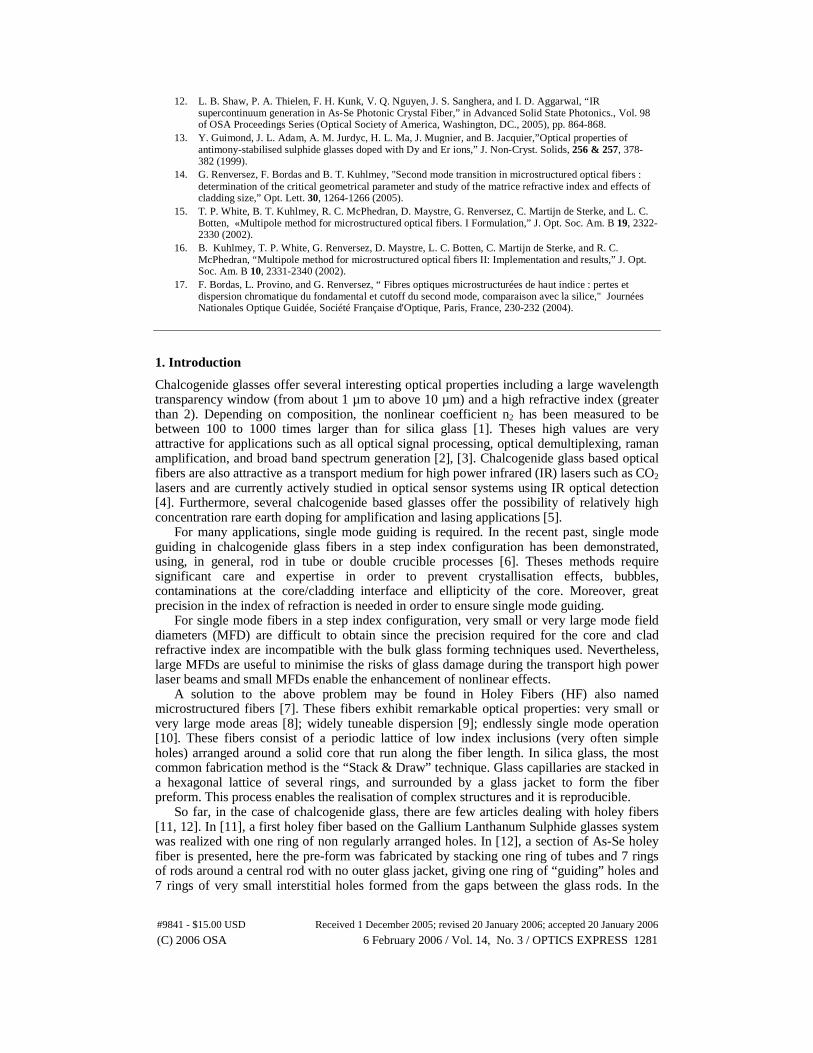
The nominal glass composition is Ga5Ge20Sb10S65 (2S2G) [13]. High purity raw materials (5N) are placed in a sealed silica tube under vacuum (10-5 mb), heated at 800°C for 12h and then quenched in water. The index of refraction is 2.25 at 1550 nm and the nonlinear coefficient, n2, is measured to be 120 times greater than that of silica. This particular glass is transparent from 0.6 µm to 10 µm (low loss fiber fabrication is possible from 1 to 6 µm). The glass transition temperature, Tg, was measured with a differential scanning calorimeter (DSC). Tg is measured to be at 305 °C as indicated by Fig. 1 which shows the thermal flux versus temperature. Between 305 °C and 500°C, this composition exhibits no crystallisation peak in the DSC curve when heated at a rate of 10°C/min.
Fig. 1. determination of transition temperature Tg by DSC measurement for 2S2G glass
Furthermore, there is shallow variation of viscosity with temperature allowing stable fiber
draw over a range of several tens of °C. These properties make this glass an ideal candidate for the “Stack and Draw” technique.
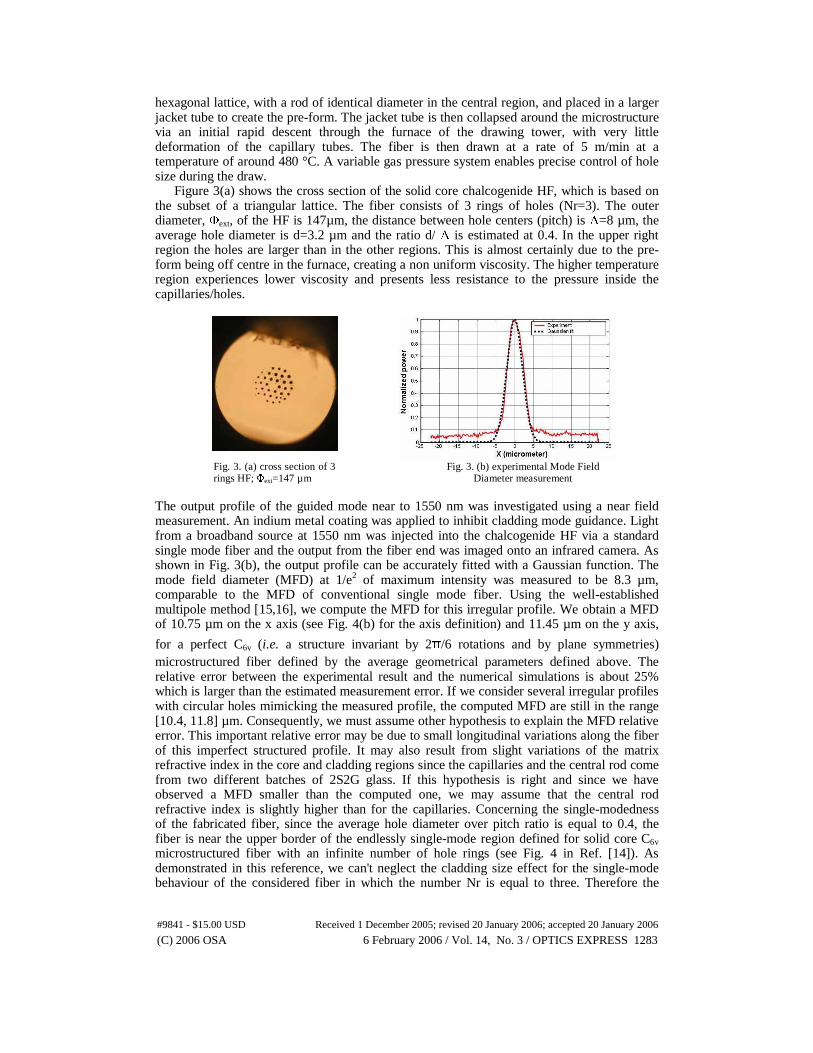
To make the core rod, the glass is quenched in water and then annealed near the glass transition temperature for 30 min and cooled down to room temperature. For tube fabrication, a glass melt at 700°C is spun at 3000 rpm at ambient temperature during several minutes [Fig. 2(a)]. During cooling, the viscosity increases and after a few minutes the vitrified tube is formed Fig. 2(b). The tube size used here is typically 12cm*12mm*5mm (length*outer diameter*inner diameter).
Fig. 2. (a) rotational casting set up Fig. 2. (b) chalcogenide tube
formed by rotational casting 3. Holey fiber fabrication and characterization
A chalcogenide (2S2G) tube, placed in a suitable furnace in a drawing tower is drawn down to form capillaries with an outer diameter typically of 665 µm. These tubes are stacked in
#9841 - $15.00 USD Received 1 December 2005; revised 20 January 2006; accepted 20 January 2006
(C) 2006 OSA 6 February 2006 / Vol. 14, No. 3 / OPTICS EXPRESS 1282
hexagonal lattice, with a rod of identical diameter in the central region, and placed in a larger jacket tube to create the pre-form. The jacket tube is then collapsed around the microstructure via an initial rapid descent through the furnace of the drawing tower, with very little deformation of the capillary tubes. The fiber is then drawn at a rate of 5 m/min at a temperature of around 480 °C. A variable gas pressure system enables precise control of hole size during the draw.
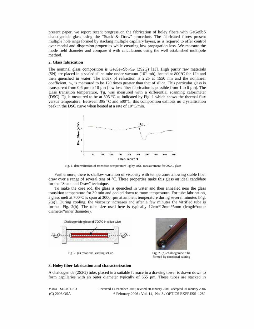
Figure 3(a) shows the cross section of the solid core chalcogenide HF, which is based on the subset of a triangular lattice. The fiber consists of 3 rings of holes (Nr=3). The outer diameter, Φext, of the HF is 147µm, the distance between hole centers (pitch) is Λ=8 µm, the average hole diameter is d=3.2 µm and the ratio d/ Λ is estimated at 0.4. In the upper right region the holes are larger than in the other regions. This is almost certainly due to the pre-form being off centre in the furnace, creating a non uniform viscosity. The higher temperature region experiences lower viscosity and presents less resistance to the pressure inside the capillaries/holes.
Fig. 3. (a) cross section of 3 rings HF; Φext=147 µm
Fig. 3. (b) experimental Mode Field Diameter measurement
The output profile of the guided mode near to 1550 nm was investigated using a near field measurement. An indium metal coating was applied to inhibit cladding mode guidance. Light from a broadband source at 1550 nm was injected into the chalcogenide HF via a standard single mode fiber and the output from the fiber end was imaged onto an infrared camera. As shown in Fig. 3(b), the output profile can be accurately fitted with a Gaussian function. The mode field diameter (MFD) at 1/e2 of maximum intensity was measured to be 8.3 µm, comparable to the MFD of conventional single mode fiber. Using the well-established multipole method [15,16], we compute the MFD for this irregular profile. We obtain a MFD of 10.75 µm on the x axis (see Fig. 4(b) for the axis definition) and 11.45 µm on the y axis,
for a perfect C6v (i.e. a structure invariant by 2π/6 rotations and by plane symmetries) microstructured fiber defined by the average geometrical parameters defined above. The relative error between the experimental result and the numerical simulations is about 25% which is larger than the estimated measurement error. If we consider several irregular profiles with circular holes mimicking the measured profile, the computed MFD are still in the range [10.4, 11.8] µm. Consequently, we must assume other hypothesis to explain the MFD relative error. This important relative error may be due to small longitudinal variations along the fiber of this imperfect structured profile. It may also result from slight variations of the matrix refractive index in the core and cladding regions since the capillaries and the central rod come from two different batches of 2S2G glass. If this hypothesis is right and since we have observed a MFD smaller than the computed one, we may assume that the central rod refractive index is slightly higher than for the capillaries. Concerning the single-modedness of the fabricated fiber, since the average hole diameter over pitch ratio is equal to 0.4, the fiber is near the upper border of the endlessly single-mode region defined for solid core C6v microstructured fiber with an infinite number of hole rings (see Fig. 4 in Ref. [14]). As demonstrated in this reference, we can't neglect the cladding size effect for the single-mode behaviour of the considered fiber in which the number Nr is equal to three. Therefore the
#9841 - $15.00 USD Received 1 December 2005; revised 20 January 2006; accepted 20 January 2006
(C) 2006 OSA 6 February 2006 / Vol. 14, No. 3 / OPTICS EXPRESS 1283
endlessly single modedness of the fabricated fiber is not guaranteed. Furthermore the imperfect profile and the supposed index difference mentioned above may also modify the single mode properties compared to the perfect C6v microstructured fiber used in the above numerical study.
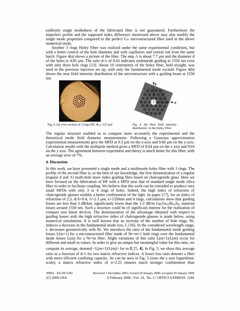
Another 3 rings Holey Fiber was realized under the same experimental conditions, but with a better control of the hole diameter and with capillaries and central rod from the same batch. Figure 4(a) shows a picture of the fiber. The step Λ is about 7.7 µm and the diameter d of the holes is 4.85 µm. The ratio d/Λ of 0.63 indicates multimode guiding at 1550 nm even with only three hole rings [13]. About 10 centimetres of the holey fiber, held straight, was used in the previous injection set up, with only the fundamental mode excited. Figure 4(b) shows the near field intensity distribution of the microstructure with a guiding beam at 1550 nm.
Fig. 4. (a) cross section of 3 rings HF; Φext=137 µm Fig. 4. (b) Near field intensity
distribution in the Holey Fiber
The regular structure enabled us to compare more accurately the experimental and the theoretical mode field diameter measurements. Following a Gaussian approximation experimental measurements give the MFD at 9.3 µm on the x-axis and 9.66 µm on the y-axis. Calculation results with the multipole method gives a MFD of 8.64 µm on the x axis and 9.03 on the y axis. The agreement between experiment and theory is much better for this fiber, with an average error of 7%.
4. Discussion
In this work, we have presented a single mode and a multimode holey fiber with 3 rings. The profile of the second fiber is, to the best of our knowledge, the first demonstration of a regular (regular d and Λ) multi-hole layer index guiding fibre based on chalcogenide glass. Here we have focused on the fabrication of HF with a MFD near that of standard single mode silica fiber in order to facilitate coupling. We believe that this work can be extended to produce very small MFDs with only 3 or 4 rings of holes. Indeed, the high index of refraction of chalcogenide glasses enables a better confinement of the light. In paper [17], for an index of refraction of 2.5, d/Λ=0.4, Λ=2.3 µm, λ=1550nm and 4 rings, calculations show that guiding losses are less than 5 dB/km, significantly lower than the 1-2 dB/m Ga5Ge20Sb10S65 material losses around 1550 nm. Such a structure could be of significant interest for the realization of compact non linear devices. The demonstration of the advantage obtained with respect to guiding losses with the high refractive index of chalcogenide glasses is made below, using numerical simulations. It is well known that an increase of the number of hole rings, Nr, induces a decrease in the fundamental mode loss, L [16]. In the considered wavelength range, L decreases geometrically with Nr. We introduce the ratio of the fundamental mode guiding losses L(m+1) for a microstructured fiber made of Nr=m+1 hole rings over the fundamental mode losses L(m) for a Nr=m fiber. Slight variations of this ratio L(m+1)/L(m) occur for different and small m values. In order to give an unique but meaningful value for this ratio, we
compute its average, denoted <L(m+1)/L(m)> for m Є [1, 4]. In Fig. 5, we show this average ratio as a function of d/Λ for two matrix refractive indices. A lower loss ratio denotes a fiber with more efficient confining capacity. As can be seen in Fig. 5 (note the y axis logarithmic scale), a matrix refractive index of n=2.25 ensures much stronger confinement than
#9841 - $15.00 USD Received 1 December 2005; revised 20 January 2006; accepted 20 January 2006
(C) 2006 OSA 6 February 2006 / Vol. 14, No. 3 / OPTICS EXPRESS 1284
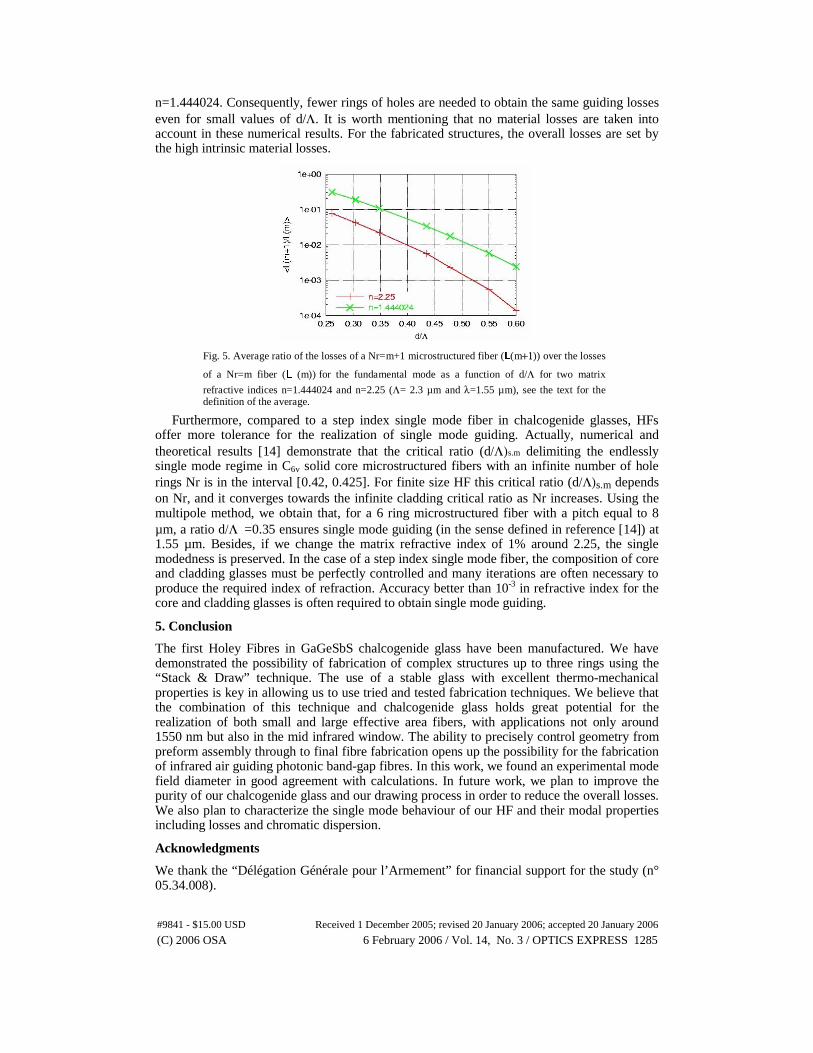
n=1.444024. Consequently, fewer rings of holes are needed to obtain the same guiding losses even for small values of d/Λ. It is worth mentioning that no material losses are taken into account in these numerical results. For the fabricated structures, the overall losses are set by the high intrinsic material losses.
Fig. 5. Average ratio of the losses of a Nr=m+1 microstructured fiber (L(m+1)) over the losses
of a Nr=m fiber (L (m)) for the fundamental mode as a function of d/Λ for two matrix
refractive indices n=1.444024 and n=2.25 (Λ= 2.3 µm and λ=1.55 µm), see the text for the definition of the average.
Furthermore, compared to a step index single mode fiber in chalcogenide glasses, HFs offer more tolerance for the realization of single mode guiding. Actually, numerical and theoretical results [14] demonstrate that the critical ratio (d/Λ)s.m delimiting the endlessly single mode regime in C6v solid core microstructured fibers with an infinite number of hole rings Nr is in the interval [0.42, 0.425]. For finite size HF this critical ratio (d/Λ)s.m depends on Nr, and it converges towards the infinite cladding critical ratio as Nr increases. Using the multipole method, we obtain that, for a 6 ring microstructured fiber with a pitch equal to 8 µm, a ratio d/Λ =0.35 ensures single mode guiding (in the sense defined in reference [14]) at 1.55 µm. Besides, if we change the matrix refractive index of 1% around 2.25, the single modedness is preserved. In the case of a step index single mode fiber, the composition of core and cladding glasses must be perfectly controlled and many iterations are often necessary to produce the required index of refraction. Accuracy better than 10-3 in refractive index for the core and cladding glasses is often required to obtain single mode guiding.
5. Conclusion
The first Holey Fibres in GaGeSbS chalcogenide glass have been manufactured. We have demonstrated the possibility of fabrication of complex structures up to three rings using the “Stack & Draw” technique. The use of a stable glass with excellent thermo-mechanical properties is key in allowing us to use tried and tested fabrication techniques. We believe that the combination of this technique and chalcogenide glass holds great potential for the realization of both small and large effective area fibers, with applications not only around 1550 nm but also in the mid infrared window. The ability to precisely control geometry from preform assembly through to final fibre fabrication opens up the possibility for the fabrication of infrared air guiding photonic band-gap fibres. In this work, we found an experimental mode field diameter in good agreement with calculations. In future work, we plan to improve the purity of our chalcogenide glass and our drawing process in order to reduce the overall losses. We also plan to characterize the single mode behaviour of our HF and their modal properties including losses and chromatic dispersion.
Acknowledgments
We thank the “Délégation Générale pour l’Armement” for financial support for the study (n° 05.34.008).
#9841 - $15.00 USD Received 1 December 2005; revised 20 January 2006; accepted 20 January 2006
(C) 2006 OSA 6 February 2006 / Vol. 14, No. 3 / OPTICS EXPRESS 1285