Embed Size (px)
Citation preview

INTERNATIONALSTANDARD
ISO14520-1
Second edition2006-02-15
Reference numberISO 14520-1:2006(E)
© ISO 2006
Gaseous fire-extinguishing systems — Physical properties and system design —
Part 1:General requirements
Systèmes d'extinction d'incendie utilisant des agents gazeux — Propriétés physiques et conception des systèmes —
Partie 1: Exigences générales
ISO 14520-1:2006(E)
ii © ISO 2006 – All rights reserved
PDF disclaimer
This PDF file may contain embedded typefaces. In accordance with Adobe's licensing policy, this file may be printed or viewed but shallnot be edited unless the typefaces which are embedded are licensed to and installed on the computer performing the editing. Indownloading this file, parties accept therein the responsibility of not infringing Adobe's licensing policy. The ISO Central Secretariataccepts no liability in this area.
Adobe is a trademark of Adobe Systems Incorporated.
Details of the software products used to create this PDF file can be found in the General Info relative to the file; the PDF-creationparameters were optimized for printing. Every care has been taken to ensure that the file is suitable for use by ISO member bodies. In theunlikely event that a problem relating to it is found, please inform the Central Secretariat at the address given below.
© ISO 2006
All rights reserved. Unless otherwise specified, no part of this publication may be reproduced or utilized in any form or by any means,electronic or mechanical, including photocopying and microfilm, without permission in writing from either ISO at the address below orISO's member body in the country of the requester.
ISO copyright officeCase postale 56 • CH-1211 Geneva 20Tel. + 41 22 749 01 11Fax + 41 22 749 09 47E-mail [email protected] www.iso.org
Published in Switzerland
ISO 14520-1:2006(E)
© ISO 2006 – All rights reserved iii
Contents Page
1 Scope .................................................................................................................................................... 1
2 Normative references .......................................................................................................................... 2
3 Terms and definitions .......................................................................................................................... 2
4 Use and limitations .............................................................................................................................. 5
5 Safety .................................................................................................................................................... 7
6 System design ................................................................................................................................... 10
7 Extinguishant system design ........................................................................................................... 16
8 Commissioning and acceptance ...................................................................................................... 24
9 Inspection, maintenance, testing and training ............................................................................... 27
Annex A (normative) Working documents ............................................................................................... 30
Annex B (normative) Determination of flame-extinguishing concentration of gaseousextinguishants by the cup burner method .............................................................................................. 32
Annex C (normative) Fire extinguishment/area coverage fire test procedure for engineeredand pre-engineered extinguishing units .................................................................................................. 38
Annex D (normative) Method of evaluating inerting concentration of a fire extinguishant ................ 58
Annex E (normative) Door fan test for determining of minimum hold time .......................................... 60
Annex F (informative) System performance verification ........................................................................ 75
Annex G (informative) Safe personnel exposure guidelines .................................................................. 76
Annex H (informative) Flow calculation implementation method and flow calculation verificationand testing for approvals .......................................................................................................................... 83
ISO 14520-1:2006(E)
iv © ISO 2006 – All rights reserved
Foreword
ISO (the International Organization for Standardization) is a worldwide federation of national standards bodies(ISO member bodies). The work of preparing International Standards is normally carried out through ISOtechnical committees. Each member body interested in a subject for which a technical committee has beenestablished has the right to be represented on that committee. International organizations, governmental andnon-governmental, in liaison with ISO, also take part in the work. ISO collaborates closely with the InternationalElectrotechnical Commission (IEC) on all matters of electrotechnical standardization.
International Standards are drafted in accordance with the rules given in the ISO/IEC Directives, Part 2.
The main task of technical committees is to prepare International Standards. Draft International Standardsadopted by the technical committees are circulated to the member bodies for voting. Publication as anInternational Standard requires approval by at least 75 % of the member bodies casting a vote.
Attention is drawn to the possibility that some of the elements of this document may be the subject of patentrights. ISO shall not be held responsible for identifying any or all such patent rights.
ISO 14520-1 was prepared by Technical Committee ISO/TC 21, Equipment for fire protection and fire fighting,Subcommittee SC 8, Gaseous media and firefighting systems using gas.
This second edition cancels and replaces the first edition (ISO 14520-1:2000), which has been technicallyrevised.
Annex C has been extensively revised to include polymeric sheet fuel array fire tests [polymethyl methacrylate(PMMA)], [polypropylene (PP)] and [acrylonitrile-butadiene-styrene (ABS)]. These tests are designed to moreclosely represent plastic fuel hazards such as may be encountered in information technology,telecommunications and process control facilities.
Annex E has been re-structured to accommodate lighter-than-air gases and to provide means for dealing withnon-standard (as opposed to geometrically regular) hazard enclosures.
Also incorporated in this revision of ISO 14520-1 are safe personnel exposure guidelines. Annex G, recognizingphysiologically based pharmacokinetic (PBPK) modelling and hypoxic guidelines to define safe humanexposure limits.
ISO 14520 consists of the following parts, under the general title Gaseous fire-extinguishing systems —Physical properties and system design:
— Part 1: General requirements
— Part 2: CF I extinguishant
— Part 5: FK-5-1-12 extinguishant
— Part 6: HCFC Blend A extinguishant
— Part 8: HFC 125 extinguishant
— Part 9: HFC 227ea extinguishant
— Part 10: HFC 23 extinguishant
— Part 11: HFC 236fa extinguishant
— Part 12: IG-01 extinguishant
— Part 13: IG-100 extinguishant
3

ISO 14520-1:2006(E)
© ISO 2006 – All rights reserved v
— Part 14: IG-55 extinguishant
— Part 15: IG-541 extinguishant
Parts 3, 4 and 7, which dealt with FC-2-1-8, FC-3-1-10 and HCFC 124 extinguishants, respectively, have beenwithdrawn, as these types are no longer manufactured.
ISO 14520-1:2006(E)
vi © ISO 2006 – All rights reserved
Introduction
Fire fighting systems covered in this part of ISO 14520 are designed to provide a supply of gaseousextinguishing medium for the extinction of fire.
Several different methods of supplying extinguishant to, and applying it at, the required point of discharge for fireextinction have been developed in recent years, and there is a need for dissemination of information onestablished systems and methods. This part of ISO 14520 has been prepared to meet this need.
In particular, new requirements to eliminate the need to release extinguishants during testing andcommissioning procedures are included. These are linked to the inclusion of enclosure integrity testing.
The requirements of this part of ISO 14520 are made in the light of the best technical data known to the workinggroup at the time of writing but, since a wide field is covered, it has been impracticable to consider everypossible factor or circumstance that might affect implementation of the recommendations.
It has been assumed in the preparation of this part of ISO 14520 that the execution of its provisions is entrustedto people appropriately qualified and experienced in the specification, design, installation, testing, approval,inspection, operation and maintenance of systems and equipment, for whose guidance it has been prepared,and who can be expected to exercise a duty of care to avoid unnecessary release of extinguishant.
Attention is drawn to the Montreal Protocol on substances that deplete the ozone layer.
It is important that the fire protection of a building or plant be considered as a whole. Gaseous extinguishantsystems form only a part, though an important part, of the available facilities, but it should not be assumed thattheir adoption necessarily removes the need to consider supplementary measures, such as the provision ofportable fire extinguishers or other mobile appliances for first aid or emergency use, or to deal with specialhazards.
Gaseous extinguishants have for many years been a recognized effective medium for the extinction ofinflammable liquid fires and fires in the presence of electrical and ordinary Class A hazards, but it should not beforgotten, in the planning of comprehensive schemes, that there may be hazards for which these media are notsuitable, or that in certain circumstances or situations there may be dangers in their use requiring specialprecautions.
Advice on these matters can be obtained from the appropriate manufacturer of the extinguishant or theextinguishing system. Information may also be sought from the appropriate fire authority, the health and safetyauthorities and insurers. In addition, reference should be made as necessary to other national standards andstatutory regulations of the particular country.
It is essential that fire fighting equipment be carefully maintained to ensure instant readiness when required.Routine maintenance is liable to be overlooked or given insufficient attention by the owner of the system. It is,however, neglected at peril to the lives of occupants of the premises and at the risk of crippling financial loss.The importance of maintenance cannot be too highly emphasized. Installation and maintenance should only bedone by qualified personnel.
Inspection preferably by a third party, should include an evaluation that the extinguishing system continues toprovide adequate protection for the risk (protected zones as well as state of the art can change over time).
The test protocol contained in Annex C of this part of ISO 14520 was developed by a special working group ofISO/TC 21/SC 8. Annex C deals with the tests for determination of the extinguishing concentrations and systemperformance and they are designed in such a way to allow individual installers to use his/her/system and carryout all of the extinguishing tests. The need for the tests presented in Annex C was established by the fact thatthe previously used Class A fire test involved wood crib, heptane pan and heptane can test fires in an enclosureof , and did not necessarily indicate extinguishing concentrations suitable for the protection of plastic fuel100 m3

ISO 14520-1:2006(E)
© ISO 2006 – All rights reserved vii
hazards such as may be encountered in information technology, telecommunications and process controlfacilities.
As a consequence of the above, the current Annex C of this part of ISO 14520 has been revised as describedin the Foreword.
Specific parts 3, 4 and 7 have been withdrawn on the basis that the extinguishing media have not beencommercialized, and a new agent specific part 5 has been introduced to cover FK-5-1-12(dodecafluoro-2-methylpentan-3-one) systems.

INTERNATIONAL STANDARD ISO 14520-1:2006(E)
© ISO 2006 – All rights reserved 1
Gaseous fire-extinguishing systems — Physical properties and system design —
Part 1:General requirements
1 Scope
This part of ISO 14520 specifies requirements and gives recommendations for the design, installation, testing,maintenance and safety of gaseous fire fighting systems in buildings, plant or other structures, and thecharacteristics of the various extinguishants and types of fire for which they are a suitable extinguishingmedium.
It covers total flooding systems primarily related to buildings, plant and other specific applications, utilizingelectrically non-conducting gaseous fire extinguishants that do not leave a residue after discharge and for whichthere are sufficient data currently available to enable validation of performance and safety characteristics by anappropriate independent authority. This part of ISO 14520 is not applicable to explosion suppression.
This part of ISO 14520 is not intended to indicate approval of the extinguishants listed therein by theappropriate authorities, as other extinguishants may be equally acceptable. CO2 is not included as it is coveredby other International Standards.
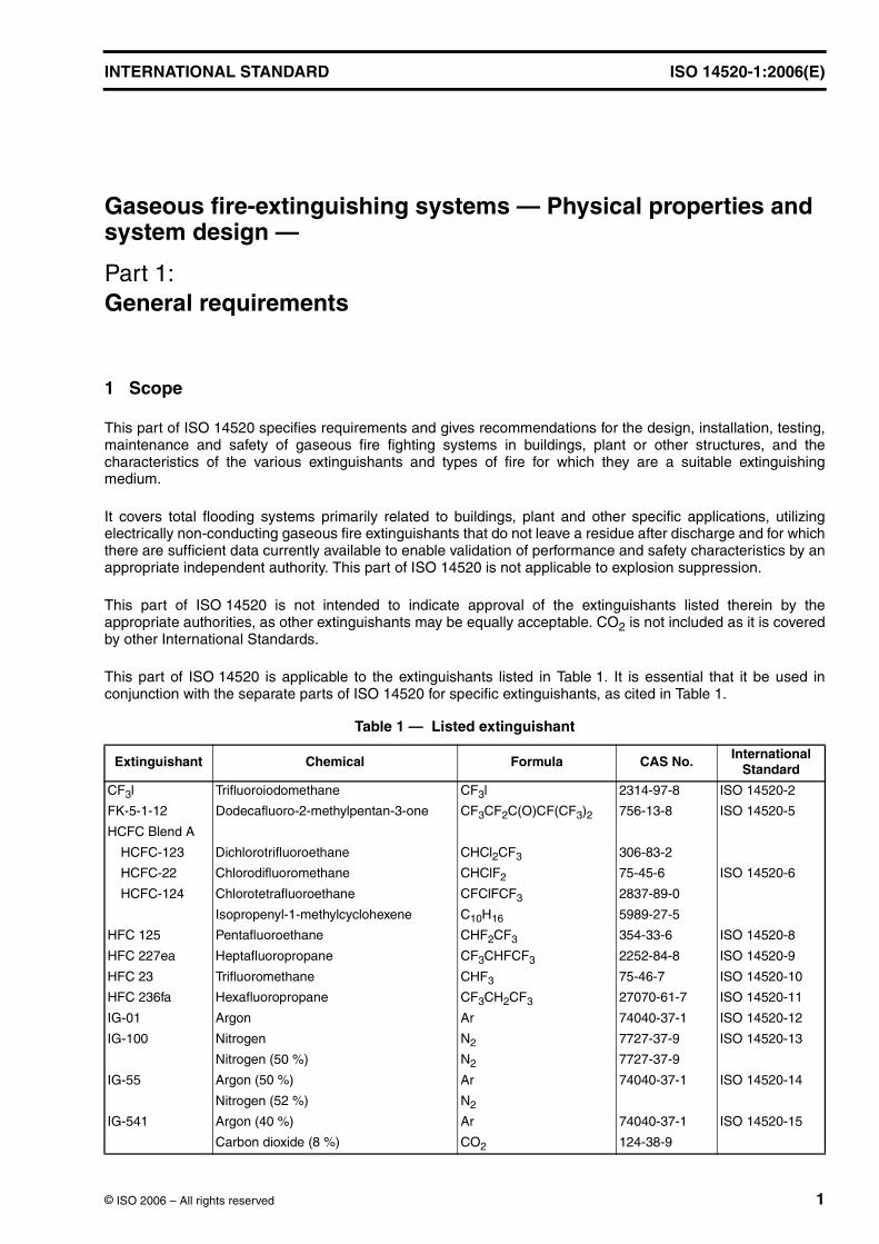
This part of ISO 14520 is applicable to the extinguishants listed in Table 1. It is essential that it be used inconjunction with the separate parts of ISO 14520 for specific extinguishants, as cited in Table 1.
Table 1 — Listed extinguishant
Extinguishant Chemical Formula CAS No. International Standard
CF3l Trifluoroiodomethane CF3l 2314-97-8 ISO 14520-2
FK-5-1-12 Dodecafluoro-2-methylpentan-3-one CF3CF2C(O)CF(CF3)2 756-13-8 ISO 14520-5
HCFC Blend A
HCFC-123 Dichlorotrifluoroethane CHCl2CF3 306-83-2
HCFC-22 Chlorodifluoromethane CHClF2 75-45-6 ISO 14520-6
HCFC-124 Chlorotetrafluoroethane CFClFCF3 2837-89-0
Isopropenyl-1-methylcyclohexene C10H16 5989-27-5
HFC 125 Pentafluoroethane CHF2CF3 354-33-6 ISO 14520-8
HFC 227ea Heptafluoropropane CF3CHFCF3 2252-84-8 ISO 14520-9
HFC 23 Trifluoromethane CHF3 75-46-7 ISO 14520-10
HFC 236fa Hexafluoropropane CF3CH2CF3 27070-61-7 ISO 14520-11
IG-01 Argon Ar 74040-37-1 ISO 14520-12
IG-100 Nitrogen N2 7727-37-9 ISO 14520-13
Nitrogen ( ) N2 7727-37-9
IG-55 Argon ( ) Ar 74040-37-1 ISO 14520-14
Nitrogen ( ) N2
IG-541 Argon ( ) Ar 74040-37-1 ISO 14520-15
Carbon dioxide ( ) CO2 124-38-9
50 %
50 %
52 %
40 %
8 %
ISO 14520-1:2006(E)
2 © ISO 2006 – All rights reserved
2 Normative references
The following referenced documents are indispensable for the application of this document. For datedreferences, only the edition cited applies. For undated references, the latest edition of the referenced document(including any amendments) applies.
ISO 3941, Classification of fires
ISO 5660-1, Reaction-to-fire tests — Heat release, smoke production and mass loss rate — Part 1: Heatrelease rate (cone calorimeter method)
ISO 14520-2, Gaseous fire-extinguishing systems — Physical properties and system design — Part 2: CF3Iextinguishant
ISO 14520-5, Gaseous fire-extinguishing systems — Physical properties and system design — Part 5:FK-5-1-12 extinguishant
ISO 14520-6, Gaseous fire-extinguishing systems — Physical properties and system design — Part 6: HCFCBlend A extinguishant
ISO 14520-8, Gaseous fire-extinguishing systems — Physical properties and system design — Part 8:HFC 125 extinguishant
ISO 14520-9, Gaseous fire-extinguishing systems — Physical properties and system design — Part 9:HFC 227ea extinguishant
ISO 14520-10, Gaseous fire-extinguishing systems — Physical properties and system design — Part 10:HFC 23 extinguishant
ISO 14520-11, Gaseous fire-extinguishing systems — Physical properties and system design — Part 11:HFC 236fa extinguishant
ISO 14520-12, Gaseous fire-extinguishing systems — Physical properties and system design — Part 12: IG-01extinguishant
ISO 14520-13, Gaseous fire-extinguishing systems — Physical properties and system design — Part 13:IG-100 extinguishant
ISO 14520-14, Gaseous fire-extinguishing systems — Physical properties and system design — Part 14: IG-55extinguishant
ISO 14520-15, Gaseous fire-extinguishing systems — Physical properties and system design — Part 15:IG-541 extinguishant
ASTM E1354-04a, Standard Test Method for Heat and Visible Smoke Release Rates for Materials and ProductsUsing an Oxygen Consumption Calorimeter
3 Terms and definitions
For the purposes of this document, the following terms and definitions apply.
NOTE For the purposes of this document, the term “bar” shall be taken as “gauge”, unless otherwise indicated.Concentrations or quantities expressed in percentages ( ) shall be taken as by volume, unless otherwise indicated.
3.1 approvedacceptable to a relevant authority (see 3.2)
NOTE In determining the acceptability of installations or procedures, equipment or materials, the authority can baseacceptance on compliance with the appropriate standards.
%
ISO 14520-1:2006(E)
© ISO 2006 – All rights reserved 3
3.2 authorityorganization, office or individual responsible for approving equipment, installations or procedures
3.3 automatic/manual switchmeans of converting the system from automatic to manual actuation
NOTE This can be in the form of a manual switch on the control panel or other units, or a personnel door interlock. In allcases, this changes the actuation mode of the system from automatic and manual to manual only or vice versa.
3.4 extinguishantelectrically non-conducting gaseous fire extinguishant that, upon evaporation, does not leave a residue (seeTable 1)
3.5 clearanceair gap between equipment, including piping and nozzles and unenclosed or uninsulated live electricalcomponents at other than ground potential
3.6 Concentration
3.6.1 design concentrationconcentration of extinguishant, including a safety factor, required for system design purposes
3.6.2 maximum concentrationconcentration achieved from the actual extinguishant quantity at the maximum ambient temperature in theprotected area
3.6.3 extinguishing concentrationminimum concentration of extinguishant required to extinguish a fire involving a particular fuel under definedexperimental conditions excluding any safety factor
3.7 engineered systemsystem in which the supply of extinguishant stored centrally is discharged through a system of pipes andnozzles in which the size of each section of pipe and nozzle orifice has been calculated in accordance withrelevant parts of ISO 14520
3.8 fill densitymass of extinguishant per unit volume of container
3.9 flooding quantitymass or volume of extinguishant required to achieve the design concentration within the protected volume
3.10 nett volumevolume enclosed by the building elements around the protected enclosure, minus the volume of any permanentimpermeable building elements within the enclosure
3.11 hold timeperiod of time during which a concentration of extinguishant greater than the fire extinguishing concentrationsurrounds the hazard
ISO 14520-1:2006(E)
4 © ISO 2006 – All rights reserved
3.12 inspectionvisual check to give reasonable assurance that the extinguishing system is fully charged and operable
NOTE This is done by seeing that the system is in place, that it has not been activated or tampered with, and that there isno obvious physical damage or condition to prevent operation.
3.13 liquefied gasgas or gas mixture (normally a halocarbon) which is liquid at the container pressurization level at roomtemperature ( )
3.14 lock-off devicemanual shut-off valve installed in the discharge piping downstream of the agent containers or another type ofdevice that mechanically prevents agent container actuation
NOTE 1 The actuation of this device provides an indication of system isolation.
NOTE 2 The intent is to prevent the discharge of agent into the hazard area when the lock-off device is activated.
3.15 lowest observed adverse effect levelLOAELlowest concentration at which an adverse toxicological or physiological effect has been observed
3.16 maintenancethorough check, comprising a thorough examination and any necessary repair or replacement of systemcomponent, to give maximum assurance that the extinguishing system will operate as intended
3.17 maximum working pressureequilibrium pressure within a container at the maximum working temperature
NOTE 1 For liquefied gases this is at the maximum fill density and can include superpressurization.
NOTE 2 The equilibrium pressure for a container in transit can differ from that in storage within a building.
3.18 no observed adverse effect levelNOAELhighest concentration at which no adverse toxicological or physiological effect has been observed
3.19 non-liquefied gasgas or gas mixture (normally an inert gas) which, under service pressure and permissible service temperatureconditions, is always present in the gaseous form
3.20 normally occupied areaarea intended for occupancy
3.21 normally unoccupied areaarea not normally occupied by people but which may be entered occasionally for brief periods
20 ◦C
ISO 14520-1:2006(E)
© ISO 2006 – All rights reserved 5
3.22 pre-engineered systemssystem consisting of a supply of extinguishant of specified capacity coupled to pipework with a balanced nozzlearrangement up to a maximum permitted design
NOTE No deviation is permitted from the limits specified by the manufacturer or authority.
3.23 safety factormultiplier of the agent extinguishing concentration to determine the agent minimum design concentration
3.24 sea level equivalent of agentthe agent concentration (volume percent) at sea level for which the partial pressure of agent matches theambient partial pressure of agent at a given altitude
3.25 sea level equivalent of oxygenthe oxygen concentration (volume percent) at sea level for which the partial pressure of oxygen matches theambient partial pressure of oxygen at a given altitude
3.26 selector valvevalve installed in the discharge piping downstream of the agent containers, to direct the agent to the appropriatehazard enclosure
NOTE It is used where one or more agent containers are arranged in order to selectively discharge agent to any of severalseparate hazard enclosures.
3.27 superpressurizationaddition of a gas to the extinguishant container, where necessary, to achieve the required pressure for propersystem operation
3.28 total flooding systemsystem arranged to discharge extinguishant into an enclosed space to achieve the appropriate designconcentration
3.29 unoccupiable areaarea which cannot be occupied due to dimensional or other physical constraints
EXAMPLE Shallow voids and cabinets.
4 Use and limitations
4.1 General
Throughout this part of ISO 14520 the word “shall” indicates a mandatory requirement; the word "should"indicates a recommendation or that which is advised but not required.
The design, installation, service and maintenance of gaseous fire-extinguishing systems shall be performed bythose competent in fire extinguishing system technology. Maintenance and installation shall only be done byqualified personnel and companies.
The hazards against which these systems offer protection, and any limitations on their use, shall be containedin the system supplier's design manual.
ISO 14520-1:2006(E)
6 © ISO 2006 – All rights reserved
Total flooding fire-extinguishing systems are used primarily for protection against hazards that are in enclosuresor equipment that, in itself, includes an enclosure to contain the extinguishant. The following are typical of suchhazards, but the list is not exhaustive:
a) electrical and electronic hazards;
b) telecommunications facilities;
c) inflammable and combustible liquids and gases;
d) other high-value assets.
4.2 Extinguishants
Any agent that is to be recognized by this part of ISO 14520 or proposed for inclusion in this part of ISO 14520,shall first be evaluated in a manner equivalent to the process used by the U.S. Environmental ProtectionAgency's (EPA) SNAP Programme or other internationally recognized extinguishing agent approval institutions.
The extinguishants referred to in this part of ISO 14520 are electrically non-conductive media.
The extinguishants and specialized system parameters are each covered individually in the parts of ISO 14520for specific extinguishants. These parts shall be used in conjunction with this part of ISO 14520.
Unless relevant testing has been carried out to the satisfaction of the authority, the extinguishants referred to inthe specific parts of ISO 14520 shall not be used on fires involving the following:
a) chemicals containing their own supply of oxygen, such as cellulose nitrate;
b) mixtures containing oxidizing materials, such as sodium chlorate or sodium nitrate;
c) chemicals capable of undergoing autothermal decomposition, such as some organic peroxides;
d) reactive metals (such as sodium, potassium, magnesium, titanium and zirconium), reactive hydrides, ormetal amides, some of which may react violently with some gaseous extinguishants;
e) environments where significant surface areas exist at temperatures greater than the breakdowntemperature of the extinguishing agent and are heated by means other than the fire.
4.3 Electrostatic discharge
Care shall be taken when discharging extinguishant into potentially explosive atmospheres. Electrostaticcharging of conductors not bonded to earth may occur during the discharge of extinguishant. These conductorsmay discharge to other objects with sufficient energy to initiate an explosion. Where the system is used forinerting, pipework shall be adequately bonded and earthed.
4.4 Compatibility with other extinguishants
Mixing of extinguishants in the same container shall be permitted only if the system is approved for use withsuch a mixture.
Systems using the simultaneous discharge of different extinguishants to protect the same enclosed space shallnot be permitted.
4.5 Temperature limitations
All devices shall be designed for the service they will encounter and shall not readily be rendered inoperative orsusceptible to accidental operation. Devices normally shall be designed to function properly from to
, or marked to indicate temperature limitations, or in accordance with manufacturers' specificationswhich shall be marked on the name-plate, or (where there is no name-plate) in the manufacturer's instructionmanual.
−20 ◦C+50 ◦C
ISO 14520-1:2006(E)
© ISO 2006 – All rights reserved 7
5 Safety
5.1 Hazard to personnel
Any hazard to personnel created by the discharge of gaseous extinguishants shall be considered in the designof the system, in particular with reference to the hazards associated with particular extinguishants in thesupplementary parts of ISO 14520. Unnecessary exposure to all gaseous extinguishants shall be avoided.
Adherence to ISO 14520 does not remove the user's statutory responsibility to comply with the appropriatesafety regulations.
The decomposition products generated by the clean agent breaking down in the presence of very high degreesof heat can be hazardous. All of the present halocarbon agents contain fluorine. In the presence of availablehydrogen (from water vapour, or the combustion process itself), the main decomposition product is hydrogenfluoride (HF).
These decomposition products have a sharp, acrid odour, even in minute concentrations of only a few parts permillion. This characteristic provides a built-in warning system for the agent, but at the same time creates anoxious, irritating atmosphere for those who must enter the hazard following a fire.
The amount of agent that can be expected to decompose in extinguishing a fire depends to a large extent on thesize of the fire, the particular clean agent, the concentration of the agent, and the length of time the agent is incontact with the flame or heated surface. If there is a very rapid build-up of concentration to the critical value,then the fire will be extinguished quickly and the decomposition will be limited to the minimum possible with thatagent. Should that agent's specific composition be such that it could generate large quantities of decompositionproducts, and the time to achieve the critical value is lengthy, then the quantity of decomposition products canbe quite great. The actual concentration of the decomposition products then depends on the volume of the roomin which the fire was burning and on the degree of mixing and ventilation.
Clearly, longer exposure of the agent to high temperatures would produce greater concentrations of thesegases. The type and sensitivity of detection, coupled with the rate of discharge, should be selected to minimizethe exposure time of the agent to the elevated temperature if the concentration of the breakdown products is tobe minimized.
Non-liquefied agents do not decompose measurably in extinguishing a fire. As such, toxic or corrosivedecomposition products are not found. However, breakdown products of the fire itself can still be substantial andcould make the area untenable for human occupancy.
5.2 Safety precautions
5.2.1 General
As acceptable alternatives to the requirements of 4.2 and 4.3, either the requirements of Annex G for safepersonnel exposure guidelines or those requirements specified by appropriate national standards may befollowed.
The safety precautions required by this part of ISO 14520 do not address toxicological or physiological effectsassociated with the products of combustion caused by fire. The maximum exposure time assumed by the safetyprecautions in this standard is . Exposure times longer than may involve physiological ortoxicological effects not addressed by this part of ISO 14520.
5 min 5 min

ISO 14520-1:2006(E)
8 © ISO 2006 – All rights reserved
5.2.2 For normally occupied areas
The minimum safety precautions taken shall be in accordance with Table 2.
5.2.3 For normally unoccupied areas
The maximum concentration shall not exceed the LOAEL for the extinguishant used unless a lock-off device isfitted.
It is recommended that systems where the NOAEL is expected to be exceeded be placed in non-automaticmode whilst the room is occupied.
WARNING — Any change to the enclosure volume, or addition or removal of fixed contents that was notcovered in the original design will affect the concentration of extinguishant. In such instances thesystem shall be recalculated to ensure that the required design concentration is achieved and themaximum concentration is consistent with Table 2.
5.2.4 For unoccupiable areas
The maximum concentration may exceed the LOAEL for the extinguishant used, without the need for a lock-offdevice to be fitted.
5.3 Occupiable areas
In areas that are protected by total flooding systems and that are capable of being occupied, the following shallbe provided.
a) Time delay devices:
1) for applications where a discharge delay does not significantly increase the threat to life or property,from fire, extinguishing systems shall incorporate a pre-discharge alarm with a time delay sufficient toallow personnel evacuation prior to discharge;
2) time delay devices shall be used only for personnel evacuation or to prepare the hazard area fordischarge.
b) Automatic/manual switch, and lock-off devices where required in accordance with 5.2.
NOTE Although lock-off devices are not always required, they are essential in some situations, particularly for somespecific maintenance functions.
c) Exit routes, which shall be kept clear at all times, and emergency lighting and adequate direction signs tominimize travel distances.
d) Outward-swinging self-closing doors that can be opened from the inside, including when locked from theoutside.
e) Continuous visual and audible alarms at entrances and designated exits inside the protected area andcontinuous visual alarms outside the protected area, which operate until the protected area has been madesafe.
f) Appropriate warning and instructions signs.
Table 2 — Minimum safety precautions
Maximum concentration Time delay device Automatic/manual switch Lock-off device
Up to and including the NOAEL Required Not required Not required
Above the NOAEL and up to the LOAEL Required Required Not required
LOAEL and above Required Required Required
NOTE The intent of this table is to avoid unnecessary exposure of occupants to the discharged extinguishant. Factors such as the timefor egress and the risk to the occupants, by the fire, should be considered when determining the system discharge time delay. Wherenational standards require other precautions, these should be implemented.
ISO 14520-1:2006(E)
© ISO 2006 – All rights reserved 9
g) Where required, pre-discharge alarms within such areas, which are distinctive from all other alarm signals,and which, upon detection of the fire, will operate immediately on commencement of time delay.
h) Means for prompt natural or forced-draft ventilation of such areas after any discharge of extinguishant.Forced-draft ventilation will often be necessary. Care shall be taken to completely dissipate hazardousatmospheres and not just move them to other locations, as most extinguishants are heavier than air.
i) Instructions and drills of all personnel within or in the vicinity of protected areas, including maintenance orconstruction personnel who may be brought into the area, to ensure their correct actions when the systemoperates.
In addition to the above requirements, the following are recommended:
— self-contained breathing apparatus should be supplied and personnel trained in its use;
— personnel should not enter the enclosure until it has been verified as being safe to do so.
5.4 Electrical hazards
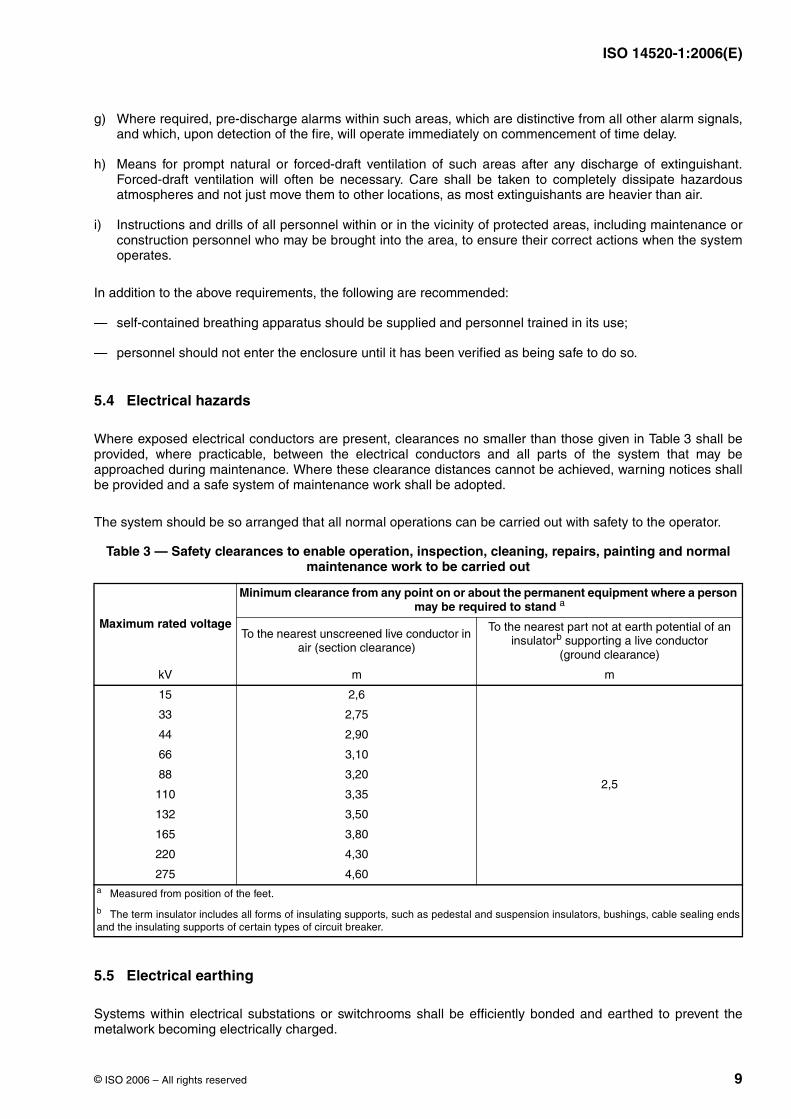
Where exposed electrical conductors are present, clearances no smaller than those given in Table 3 shall beprovided, where practicable, between the electrical conductors and all parts of the system that may beapproached during maintenance. Where these clearance distances cannot be achieved, warning notices shallbe provided and a safe system of maintenance work shall be adopted.
The system should be so arranged that all normal operations can be carried out with safety to the operator.
5.5 Electrical earthing
Systems within electrical substations or switchrooms shall be efficiently bonded and earthed to prevent themetalwork becoming electrically charged.
Table 3 — Safety clearances to enable operation, inspection, cleaning, repairs, painting and normal maintenance work to be carried out
Maximum rated voltage
Minimum clearance from any point on or about the permanent equipment where a person may be required to stand a
To the nearest unscreened live conductor in air (section clearance)
To the nearest part not at earth potential of an insulatorb supporting a live conductor
(ground clearance)
kV m m
15 2,6
2,5
33 2,75
44 2,90
66 3,10
88 3,20
110 3,35
132 3,50
165 3,80
220 4,30
275 4,60a Measured from position of the feet.
b The term insulator includes all forms of insulating supports, such as pedestal and suspension insulators, bushings, cable sealing endsand the insulating supports of certain types of circuit breaker.
ISO 14520-1:2006(E)
10 © ISO 2006 – All rights reserved
5.6 Electrostatic discharge
The system shall be adequately bonded and earthed to minimize the risk of electrostatic discharge.
6 System design
6.1 General
This clause sets out the requirements for the design of the extinguishing system.
All ancillary systems and components shall comply with the relevant national or International Standards.
6.2 Extinguishant supply
6.2.1 Quantity
6.2.1.1 The amount of extinguishant in the system shall be at least sufficient for the largest single hazard orgroup of hazards that are to be protected against simultaneously.
6.2.1.2 Where required, the reserve quantity shall be as many multiples of the main supply as the authorityconsiders necessary.
6.2.1.3 Where uninterrupted protection is required, both the main and reserve supply shall be permanentlyconnected to the distribution piping and arranged for easy changeover.
6.2.2 Quality
The extinguishant shall comply with the relevant part of ISO 14520.
6.2.3 Container arrangement
6.2.3.1 Arrangements shall be made for container and valve assemblies and accessories to be accessible forinspection, testing and other maintenance when required.
6.2.3.2 Containers shall be adequately mounted and suitably supported according to the systems installationmanual so as to provide for convenient individual servicing of the container and its contents.
6.2.3.3 Containers shall be located as near as is practical to the enclosure they protect, preferably outside theenclosure. Containers can be located within the enclosure only if sited so as to minimize the risk of exposure tofire and explosion.
6.2.3.4 Storage containers shall not be located where they will be subjected to severe weather conditions or topotential damage due to mechanical, chemical or other causes. Where potentially damaging exposure orunauthorized interference are likely, suitable enclosures or guards shall be provided.
NOTE Direct sunlight has the potential to increase the container temperature above that of the surrounding atmospherictemperature.
6.2.4 Storage containers
6.2.4.1 General
Containers shall be designed to hold the specific extinguishant. Containers shall not be charged to a fill densitygreater than specified in this part of ISO 14520 relating to the specific extinguishant.
ISO 14520-1:2006(E)
© ISO 2006 – All rights reserved 11
The containers used in these systems shall be designed to meet the requirements of relevant nationalstandards.
Where required, the container and valve assembly should be fitted with a pressure relief device complying withthe appropriate national standard.
6.2.4.2 Contents indication
Means shall be provided to indicate that each container is correctly charged.
6.2.4.3 Marking
Each halocarbon container shall have a permanent name-plate or other permanent marking specifying theextinguishant, tare and gross mass, and the superpressurization level (where applicable) of the container. Eachinert gas container shall have a permanent marking specifying the extinguishant, pressurization level of thecontainer and nominal volume.
6.2.4.4 Manifolded containers
When two or more containers are connected to the same manifold, automatic means (such as check valves)shall be provided to prevent extinguishant loss from the manifold if the system is operated when any containersare removed for maintenance.
Containers connected to a common manifold in a system shall be:
a) of the same nominal form and capacity;
b) filled with the same nominal mass of extinguishant;
c) pressurized to the same nominal working pressure.
Different sized storage containers connected to a common manifold may be used for non-liquefied gascontainers, provided they are all pressurized to the same nominal working pressure.
6.2.4.5 Operating temperatures
Unless otherwise approved, in-service container operating temperatures for total flooding systems shall notexceed nor be less than . (See also 7.3.1.)
External heating or cooling should be used to keep the temperature of the storage container within the specifiedrange unless the system is designed for proper operation with operating temperatures outside this range.
6.3 Distribution
6.3.1 General
6.3.1.1 Pipework and fittings shall comply with the appropriate national standards, shall be non-combustibleand able to withstand the expected pressures and temperatures without damage.
6.3.1.2 Before final assembly, pipe and fittings shall be inspected visually to ensure they are clean and free ofburrs and rust, and that no foreign matter is inside and the full bore is clear. After assembly, the system shall bethoroughly blown through with dry air or other compressed gas.
A dirt trap consisting of a tee with a capped nipple, at least long, shall be installed at the end of each piperun. Drain traps protected against interference by unauthorized personnel should be fitted at the lowest pointsin the pipework system if there is any possibility of a build up of water.
50 ◦C −20 ◦C
50 mm
ISO 14520-1:2006(E)
12 © ISO 2006 – All rights reserved
6.3.1.3 In systems where valve arrangements introduce sections of closed piping, such sections shall beequipped with the following:
a) indication of extinguishant trapped in piping;
b) means for safe manual venting (see 6.3.1.4);
c) automatic relief of over pressures, where required.
Over-pressure relief devices shall be designed to operate at a pressure no greater than the test pressure of thepipework, or as required by the appropriate national standard.
6.3.1.4 Pressure relief devices, which can include the selector valve, shall be fitted so that the discharge, in theevent of operation, will not injure or endanger personnel and, if necessary, so that the discharge is piped to anarea where it will not become a hazard to personnel.
6.3.1.5 In systems using pressure-operated container valves, automatic means shall be provided to vent anycontainer leakage that could build up pressure in the pilot system and cause unwanted opening of the containervalve. The means of pressure venting shall not prevent operation of the container valve.
6.3.1.6 The manifolds to the container and valve assembly shall be hydraulically tested by the manufacturer toa minimum pressure of 1,5 maximum working pressure (see 3.17), or as required by the appropriate nationalstandards.
6.3.1.7 Adequate protection shall be given to pipes, fittings or support brackets and steelwork that are likely tobe affected by corrosion. Special corrosion-resistant materials or coatings shall be used in highly corrosiveatmospheres.
6.3.2 Piping
6.3.2.1 Piping shall be of non-combustible material having physical and chemical characteristics such that itsintegrity under stress can be predicted with reliability. The thickness of the pipe wall shall be calculated inaccordance with the relevant national standard. The pressure for this calculation shall be the developedpressure at a maximum storage temperature of not less than . If higher operating temperatures areapproved for a given system, the design pressure shall be adjusted to the developed pressure at maximumtemperature. In performing this calculation, all joint factors and threading, grooving or welding allowances shallbe taken into account. If selector valves are used, this lower maximum working pressure shall not be usedupstream of the selector valves.
Where a static pressure-reducing device is used in a non-liquefied gas system, the maximum working pressurein the distribution pipework downstream of the device shall be used in the calculation of the downstream pipewall thickness.
6.3.2.2 Cast iron and non-metallic pipes shall not be used.
6.3.2.3 Flexible tubing or hoses (including connections) shall be of approved materials and shall be suitable forservice at the anticipated extinguishant pressure and maximum and minimum temperatures.
6.3.3 Fittings
6.3.3.1 Fittings shall have a minimum rated working pressure equal to or greater than the maximum pressurein the container at , or the temperature specified in the national standard, when filled to the maximumpermissible fill density for the extinguishant being used. For systems that use a pressure-reducing device in thedistribution piping, the fittings downstream of the device shall have a minimum rated working pressure equal toor greater than the maximum anticipated pressure in the downstream piping. If selector valves are used, thislower maximum working pressure shall not be used upstream of the selector valves.
Cast iron fittings shall not be used.
6.3.3.2 Welding and brazing alloys shall have a melting point above .
×
50 ◦C
50 ◦C
500 ◦C
ISO 14520-1:2006(E)
© ISO 2006 – All rights reserved 13
6.3.3.3 Welding shall be performed in accordance with relevant national standards.
6.3.3.4 Where copper, stainless steel or other suitable tubing is joined with compression fittings, themanufacturer's pressure/temperature ratings of the fitting shall not be exceeded and care shall be taken toensure the integrity of the assembly.
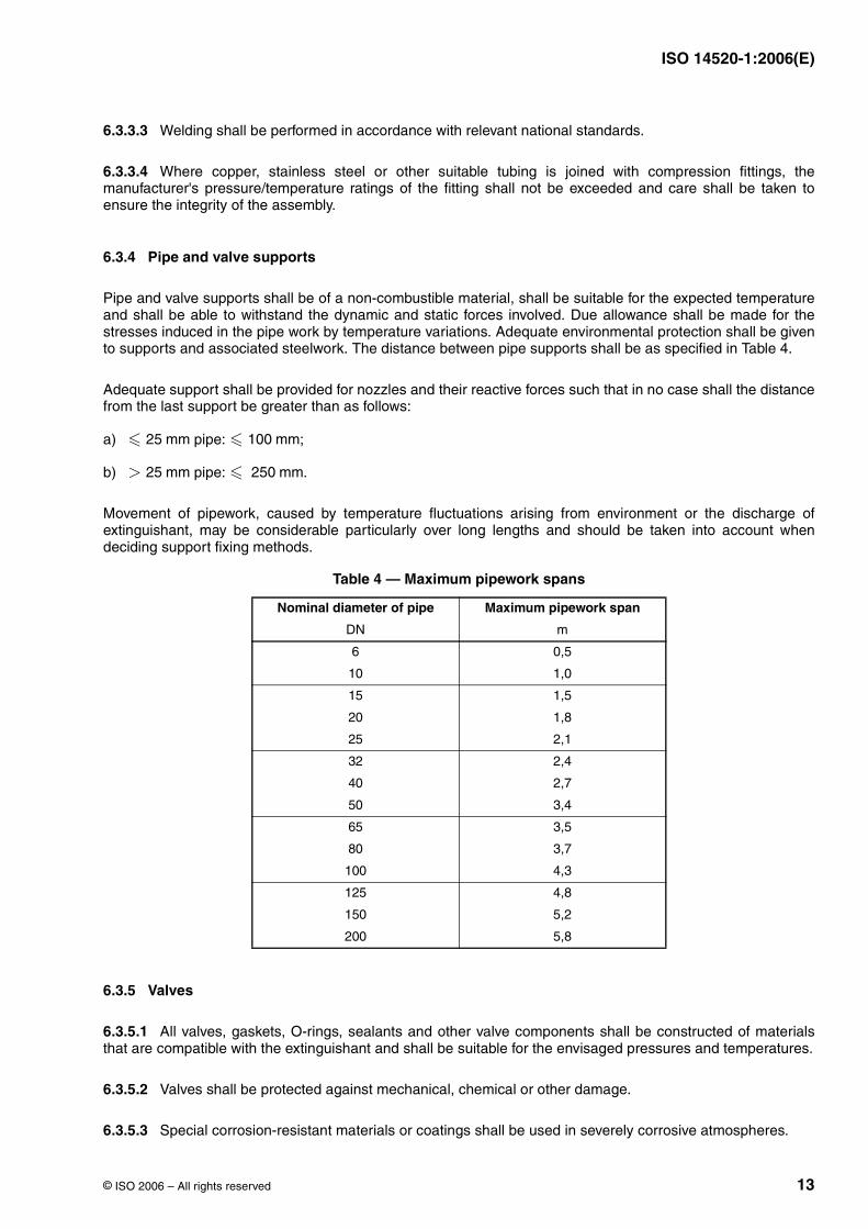
6.3.4 Pipe and valve supports
Pipe and valve supports shall be of a non-combustible material, shall be suitable for the expected temperatureand shall be able to withstand the dynamic and static forces involved. Due allowance shall be made for thestresses induced in the pipe work by temperature variations. Adequate environmental protection shall be givento supports and associated steelwork. The distance between pipe supports shall be as specified in Table 4.
Adequate support shall be provided for nozzles and their reactive forces such that in no case shall the distancefrom the last support be greater than as follows:
a) pipe: ;
b) pipe: .
Movement of pipework, caused by temperature fluctuations arising from environment or the discharge ofextinguishant, may be considerable particularly over long lengths and should be taken into account whendeciding support fixing methods.
6.3.5 Valves
6.3.5.1 All valves, gaskets, O-rings, sealants and other valve components shall be constructed of materialsthat are compatible with the extinguishant and shall be suitable for the envisaged pressures and temperatures.
6.3.5.2 Valves shall be protected against mechanical, chemical or other damage.
6.3.5.3 Special corrosion-resistant materials or coatings shall be used in severely corrosive atmospheres.
Table 4 — Maximum pipework spans
Nominal diameter of pipe Maximum pipework span
DN m
6 0,5
10 1,0
15 1,5
20 1,8
25 2,1
32 2,4
40 2,7
50 3,4
65 3,5
80 3,7
100 4,3
125 4,8
150 5,2
200 5,8
� 25 mm � 100 mm
> 25 mm � 250 mm
ISO 14520-1:2006(E)
14 © ISO 2006 – All rights reserved
6.3.6 Nozzles
6.3.6.1 Nozzle choice and location
Nozzles, including nozzles directly attached to containers, shall be approved and shall be located with thegeometry of the enclosure taken into consideration.
The type number and placement of nozzles shall be such that:
a) the design concentration is achieved in all parts of the enclosure (see also Annex C);
b) the discharge does not unduly splash inflammable liquids or create dust clouds that might extend the fire,create an explosion or otherwise adversely affect the occupants;
c) the velocity of discharge does not adversely affect the enclosure or its contents.
Where clogging by foreign materials is possible, the discharge nozzles shall be provided with frangible discs orblow-out caps. These devices shall provide an unobstructed opening upon system operation and shall bedesigned and arranged so they will not injure personnel.
Nozzles shall be suitable for the intended use and shall be approved for discharge characteristics, includingarea coverage and height limitations (see also Annex C), or shall be approved under the procedure described innational or international nozzle standards.
Nozzles shall be of adequate strength for use with the expected working pressures, they shall be able to resistnominal mechanical abuse and shall be constructed to withstand expected temperatures without deformation.
Nozzle discharge orifice inserts shall be of corrosion-resistant material.
6.3.6.2 Nozzles in ceiling tiles
In order to minimize the possibility of lifting or displacement of lightweight ceiling tiles, precautions shall betaken to securely anchor tiles for a minimum distance of from each discharge nozzle.
NOTE The discharge velocities created by the design of nozzles can be a factor in the displacement of ceiling tiles.
6.3.6.3 Marking
Discharge nozzles shall be permanently marked to identify the manufacturer and size of the orifice.
6.3.6.4 Filters
The inlet of any nozzle assembly or pressure-reducing assembly which contains an orifice of area less than shall be provided with an internal filter capable of preventing obstruction of the orifice.
6.3.7 Pressure reducing orifice assembly
Pressure reducing orifice assemblies shall be permanently marked to identify the size of the orifice. Thismarking shall be readily visible after the assembly is installed.
6.4 Detection, actuation and control systems
6.4.1 General
Detection, actuation and control systems may be either automatic or manual. Where they are automatic,provision shall also be made for manual operation.
1,5 m
7 mm2
ISO 14520-1:2006(E)
© ISO 2006 – All rights reserved 15
Detection, actuation, alarm and control systems shall be installed, tested and maintained in accordance withappropriate national standards.
Unless otherwise specified in a national standard, minimum standby sources of energy shall be used toprovide for operation of the detection, signalling, control and actuation requirements of the system.
6.4.2 Automatic detection
Automatic detection shall be by any method or device acceptable to the authority and shall be capable of earlydetection and indication of heat, flame, smoke, combustible vapours or any abnormal condition in the hazardthat is likely to produce fire.
NOTE Detectors installed at the maximum approved spacing for fire alarm use can result in excessive delay inextinguishant release, especially where more than one detection device is required to be in alarm before automatic actuationresults.
6.4.3 Operating devices
6.4.3.1 Automatic operation
Automatic systems shall be controlled by automatic fire detection and actuation systems suitable for the systemand hazard, and shall also be provided with a means of manual operation.
Electrically operated fire detection systems shall comply with the appropriate national standard. The electricpower supply shall be independent of the supply for the hazard area, and shall include an emergencysecondary power supply with automatic changeover in case the primary supply fails.
When two or more detectors are used, such as those for detecting smoke or flame, it is preferable for the systemto operate only after signals from two detectors have been received.
6.4.3.2 Manual operation
Provision shall be made for manual operation of the fire fighting system by means of a control situated outsidethe protected space or adjacent to the main exit from the space.
In addition to any means of automatic operation, the system shall be provided with the following:
a) one or more means, remote from the containers, of manual operation;
b) a manual device for providing direct mechanical actuation of the system or an electrical manual releasesystem in which the control equipment monitors for abnormal conditions in the power supply and provides asignal when the power source is inadequate.
Manual operation shall cause simultaneous operation of the appropriate automatically operated valves forextinguishant release and distribution.
NOTE 1 National standards may not require a manual release, or may require the release to operate via the pre-dischargealarms and time delay.
The manual operation device shall incorporate a double action or other safety device to restrict accidentaloperation. The device shall be provided with a means of preventing operation during maintenance of thesystem.
NOTE 2 The choice of the means of operation will depend upon the nature of the hazard to be protected. Automatic firedetection and alarm equipment will normally be provided on a manual system to indicate the presence of a fire.
24 h
ISO 14520-1:2006(E)
16 © ISO 2006 – All rights reserved
6.4.4 Control equipment
6.4.4.1 Electric control equipment
Electric control equipment shall be used to supervise the detecting circuits, manual and automatic releasingcircuits, signalling circuits, electrical actuating devices and associated wiring and, when required, causeactuation. The control equipment shall be capable of operation with the number and type of actuating devicesutilized.
6.4.4.2 Pneumatic control equipment
Where pneumatic control equipment is used, the lines shall be protected against crimping and mechanicaldamage. Where installations could be exposed to conditions that could lead to loss of integrity of the pneumaticlines, special precautions shall be taken to ensure that no loss of integrity occurs.
6.4.5 Operating alarms and indicators
6.4.5.1 Alarms or indicators, or both, shall be used to indicate the operation of the system, hazards topersonnel or failure of any supervised device. The type (audible, visual or olfactory), number and location of thedevices shall be such that their purpose is satisfactorily accomplished. The extent and type of alarms orindicator equipment, or both, shall be approved.
6.4.5.2 Audible and visual pre-discharge alarms shall be provided within the protected area to give positivewarning of impending discharge. The operation of the warning devices shall be continued after extinguishantdischarge, until positive action has been taken to acknowledge the alarm and proceed with appropriate action.
6.4.5.3 Alarms indicating failure of supervised devices or equipment shall give prompt and positive indicationof any failure and shall be distinct from alarms indicating operation or hazardous conditions.
6.4.6 Hold switches
Hold switches, where provided, shall be located within the protected area and shall be located near the meansof egress for the area. The hold switch shall be a type that requires constant manual force to inhibit systemoperation. Operation of the hold function shall result in both audible and distinct visual indication of systemimpairment. Operation of the hold switch when the system is in the quiescent state shall result in a faultindication at the control unit. The hold switch shall be clearly recognizable for the purpose intended.
7 Extinguishant system design
7.1 General
This clause sets out the requirements for the specifications, system flow calculations and extinguishantconcentrations. It shall be read in conjunction with the appropriate part of ISO 14520 for the specific agent.
7.2 Specifications, plans and approvals
7.2.1 Specifications
Specifications for gaseous fire-extinguishing systems shall be prepared under the supervision of a person fullyexperienced in the design of gaseous extinguishing systems and, where appropriate, with the advice of theauthority. The specifications shall include all pertinent items necessary for the proper design of the system suchas the designation of the authority, variances from the standard to be permitted by the authority, design criteria,system sequence of operations, the type and extent of the acceptance testing to be performed after installationof the system and owner training requirements. Extinguishant specifications are included in the various parts ofISO 14520 for the specific agent.
ISO 14520-1:2006(E)
© ISO 2006 – All rights reserved 17
7.2.2 Working documents
Layout and system proposal documents shall be submitted for approval to the authority before installation ormodification begins. The type of documentation required is specified in Annex A.
7.3 System flow calculations
7.3.1 General
System flow calculations shall be carried out at a nominal extinguishant storage temperature of , shallhave been validated by an accredited approval authority by appropriate tests such as those described in thispart of ISO 14520, and shall be properly identified. The system design shall be within the manufacturer'sspecified limitations (see also Annex H).
NOTE 1 Variations from the nominal storage temperature affect flow conditions used in calculations.
NOTE 2 Pre-engineered systems do not require a flow calculation when used within approved limitations.
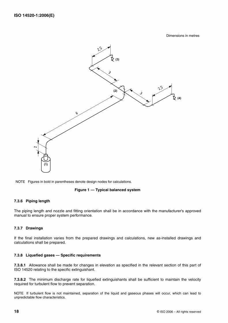
7.3.2 Balanced and unbalanced system
7.3.2.1 A balanced system shall be one in which:
a) actual or equivalent pipe lengths from the container to each nozzle are all within of each other;
b) the discharge rate of each nozzle is the same (see Figure 1).
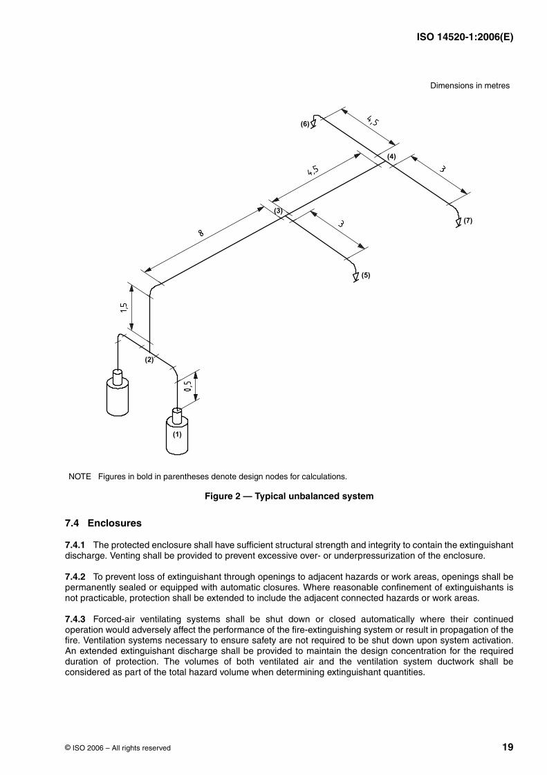
7.3.2.2 Any system that does not meet these criteria shall be considered to be an unbalanced system (seeFigure 2).
7.3.3 Friction losses
Allowance shall be made for the friction losses in pipes and in container valves, dip tubes, flexible connectors,selector valves, time delay devices and other equipment (e.g. pressure-reducing devices) within the flow line.
NOTE The flow of a liquefied gas has been demonstrated to be a two-phase phenomenon, the fluid consisting of a mixtureof liquid and vapour the proportions of which are dependent on pressure and temperature. The pressure drop is non-linear,with an increasing rate of pressure loss as the line pressure reduced by pipe friction.
7.3.4 Pressure drop
The pressure drop shall be calculated using two-phase flow equations for liquefied gases and single-phase flowequations for non-liquefied gases.
NOTE These equations use friction factors and constants dependent on pressure and density obtained empirically. As theequations cannot be solved directly, a computer program is usually used to assist with the large number of iterativecalculations in which pipe and nozzle sizes and, if appropriate, size of pressure reducing devices are selected withinprescribed pressure losses.
7.3.5 Valves and fittings
Valves, fittings and check valves shall be rated for resistance coefficient or equivalent length in terms of pipe, ortubing sizes with which they will be used. The equivalent length of the cylinder valves shall be listed and shallinclude syphon tube (where fitted), valve, discharge head, flexible connector and check valve.
20 ◦C
20 ◦C
10 %
ISO 14520-1:2006(E)
18 © ISO 2006 – All rights reserved
7.3.6 Piping length
The piping length and nozzle and fitting orientation shall be in accordance with the manufacturer's approvedmanual to ensure proper system performance.
7.3.7 Drawings
If the final installation varies from the prepared drawings and calculations, new as-installed drawings andcalculations shall be prepared.
7.3.8 Liquefied gases — Specific requirements
7.3.8.1 Allowance shall be made for changes in elevation as specified in the relevant section of this part ofISO 14520 relating to the specific extinguishant.
7.3.8.2 The minimum discharge rate for liquefied extinguishants shall be sufficient to maintain the velocityrequired for turbulent flow to prevent separation.
NOTE If turbulent flow is not maintained, separation of the liquid and gaseous phases will occur, which can lead tounpredictable flow characteristics.
Dimensions in metres
NOTE Figures in bold in parentheses denote design nodes for calculations.
Figure 1 — Typical balanced system
ISO 14520-1:2006(E)
© ISO 2006 – All rights reserved 19
7.4 Enclosures
7.4.1 The protected enclosure shall have sufficient structural strength and integrity to contain the extinguishantdischarge. Venting shall be provided to prevent excessive over- or underpressurization of the enclosure.
7.4.2 To prevent loss of extinguishant through openings to adjacent hazards or work areas, openings shall bepermanently sealed or equipped with automatic closures. Where reasonable confinement of extinguishants isnot practicable, protection shall be extended to include the adjacent connected hazards or work areas.
7.4.3 Forced-air ventilating systems shall be shut down or closed automatically where their continuedoperation would adversely affect the performance of the fire-extinguishing system or result in propagation of thefire. Ventilation systems necessary to ensure safety are not required to be shut down upon system activation.An extended extinguishant discharge shall be provided to maintain the design concentration for the requiredduration of protection. The volumes of both ventilated air and the ventilation system ductwork shall beconsidered as part of the total hazard volume when determining extinguishant quantities.
Dimensions in metres
NOTE Figures in bold in parentheses denote design nodes for calculations.
Figure 2 — Typical unbalanced system
ISO 14520-1:2006(E)
20 © ISO 2006 – All rights reserved
All services within the protected enclosure (e.g. fuel and power supplies, heating appliances, paint spraying)that are likely to impair the performance of the extinguishing system should be shut down prior to, orsimultaneously with, the discharge of the extinguishant.
7.5 Extinguishant concentration requirements
7.5.1 Flame extinguishment
7.5.1.1 For fire classifications, see ISO 3941.
7.5.1.2 The minimum Class B design concentration for each extinguishant shall be a demonstratedextinguishing concentration for each Class B fuel plus a safety factor of 1,3. The extinguishing concentrationused shall be that demonstrated by the cup burner test, carried out in accordance with the method set out inAnnex B, that has been verified with the heptane pan tests detailed in C.5.2. For hazards involving multiplefuels, the value for the fuel requiring the greatest design concentration shall be used. The extinguishingconcentration shall be taken as the cup burner value or the heptane pan test value (see Annex C), whichever isgreater.
7.5.1.3 The extinguishing concentration for Class A surface fires shall be the greater of the values determinedby the wood crib and polymeric sheet fire tests described in Annex C. The minimum design concentration forClass A fires shall be the extinguishing concentration increased by a safety factor of 1,3. For non-cellulosicClass A fuels, higher design concentrations may be required.
CAUTION — It is recognized that the wood crib and polymeric sheet Class A fire tests may notadequately indicate extinguishing concentrations suitable for the protection of certain plastic fuelhazards (e.g. electrical and electronic type hazards involving grouped power or data cables such ascomputer and control room under-floor voids, telecommunication facilities, etc.). An extinguishingconcentration not less than that determined in accordance with 7.5.1.3, or not less than of thatdetermined from the heptane fire test described in C.6.2, whichever is the greater, should be used undercertain conditions. These conditions may include:
1) cable bundles greater than in diameter;
2) cable trays with a fill density greater than of the tray cross-section;
3) horizontal or vertical stacks of cable trays (closer than );
4) equipment energized during the extinguishment period where the collective power consumptionexceeds .
If polymeric sheet fire test data are not available, an extinguishing concentration of thatdetermined from the heptane fire test shall be used.
The safety factor of 1,3 relates to the increase of from the extinguishing concentration to the designconcentration, which results in additional quantity of agent. Circumstances which may not be adequatelycovered by this factor (although in some cases they are covered by other requirements in this part ofISO 14520) and which may need allowance for additional extinguishant (i.e. more than ) are included butnot limited to the following.
a) Where leakage occurs from a non-tight enclosure. This is covered in this part of ISO 14520 by therequirement for a room integrity test and sealing of the enclosure to achieve a defined hold time.
b) Where leakage occurs due to doors being opened during or immediately after discharge. This should becovered by operational protocols for individual risks.
c) Where it is important to minimize the quantities of toxic or corrosive products of combustion from the fire.
d) Where it is important to minimize the toxic or corrosive breakdown products from the extinguishant itself.
e) Where excessive leakage occurs from an enclosure due to expansion of the extinguishant.
95 %
100 mm
20 %
250 mm
5 kW
95 %
30 %
30 %
ISO 14520-1:2006(E)
© ISO 2006 – All rights reserved 21
f) Where hot surfaces, heated by fire or other means, may cause degradation of the extinguishing agent andhence reduce the efficiency of the agent.
g) Where metal surfaces, heated by the fire, may act as an ignition source if not adequately cooled duringagent discharge and hold time.
In practice, application of this part of ISO 14520 is likely to result in higher safety factors, e.g. by the applicationof gross volumes rather than net volumes and design of systems for minimum anticipated temperatures, ratherthan those that apply in real conditions.
WARNING — Under certain conditions, it may be dangerous to extinguish a burning gas jet. As a firstmeasure, shut off the gas supply.
7.5.2 Inerting
Inerting concentrations shall be used where conditions for subsequent reflash or explosion could exist. Theseconditions exist when both
a) the quantity of fuel permitted in the enclosure is sufficient to develop a concentration equal to or greater thanone-half of the lower inflammable limit throughout the enclosure and
b) the volatility of the fuel before the fire is sufficient to reach the lower inflammable limit in air (maximumambient temperature or fuel temperature exceeds the closed cup flash point temperature) or the systemresponse is not rapid enough to detect and extinguish the fire before the volatility of the fuel is increased toa dangerous level as a result of the fire.
The minimum design concentrations used to inert atmospheres involving inflammable liquids and gases shallbe determined by the test specified in Annex D, plus a safety factor of .
7.6 Total flooding quantity
7.6.1 General
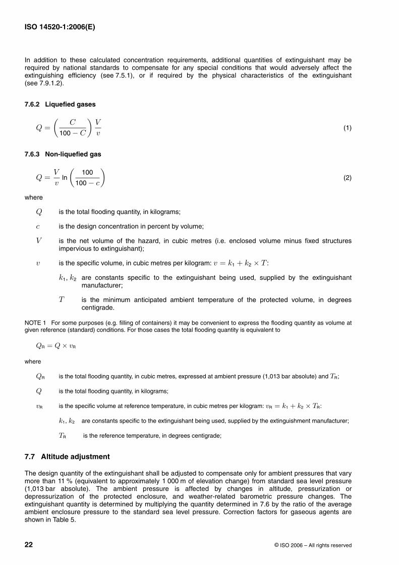
The amount of extinguishant required to achieve the design concentration shall be calculated fromEquations (1) or (2) as appropriate, or from the data in Table 3 of ISO 14520-2, ISO 14520-5, ISO 14520-8,ISO 14520-9, ISO 14520-10, ISO 14520-11, ISO 14520-12, ISO 14520-13 and ISO 14520-15 and in Table 4 ofISO 14520-6.
10 %
ISO 14520-1:2006(E)
22 © ISO 2006 – All rights reserved
In addition to these calculated concentration requirements, additional quantities of extinguishant may berequired by national standards to compensate for any special conditions that would adversely affect theextinguishing efficiency (see 7.5.1), or if required by the physical characteristics of the extinguishant(see 7.9.1.2).
7.6.2 Liquefied gases
(1)
7.6.3 Non-liquefied gas
(2)
where
is the total flooding quantity, in kilograms;
is the design concentration in percent by volume;
is the net volume of the hazard, in cubic metres (i.e. enclosed volume minus fixed structuresimpervious to extinguishant);
is the specific volume, in cubic metres per kilogram: :
, are constants specific to the extinguishant being used, supplied by the extinguishantmanufacturer;
is the minimum anticipated ambient temperature of the protected volume, in degreescentigrade.
NOTE 1 For some purposes (e.g. filling of containers) it may be convenient to express the flooding quantity as volume atgiven reference (standard) conditions. For those cases the total flooding quantity is equivalent to
where
is the total flooding quantity, in cubic metres, expressed at ambient pressure (1,013 bar absolute) and ;
is the total flooding quantity, in kilograms;
is the specific volume at reference temperature, in cubic metres per kilogram: :
, are constants specific to the extinguishant being used, supplied by the extinguishment manufacturer;
is the reference temperature, in degrees centigrade;
7.7 Altitude adjustment
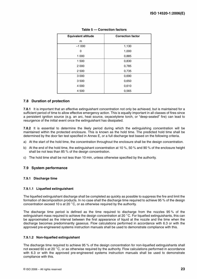
The design quantity of the extinguishant shall be adjusted to compensate only for ambient pressures that varymore than (equivalent to approximately of elevation change) from standard sea level pressure(1,013 bar absolute). The ambient pressure is affected by changes in altitude, pressurization ordepressurization of the protected enclosure, and weather-related barometric pressure changes. Theextinguishant quantity is determined by multiplying the quantity determined in 7.6 by the ratio of the averageambient enclosure pressure to the standard sea level pressure. Correction factors for gaseous agents areshown in Table 5.
Q =(
C
100 − C
)V
v
Q =V
vln
(100
100 − c
)
Q
c
V
v v = k1 + k2 × T
k1 k2
T
QR = Q × vR
QR TR
Q
vR vR = k1 + k2 × TR
k1 k2
TR
11 % 1 000 m
ISO 14520-1:2006(E)
© ISO 2006 – All rights reserved 23
7.8 Duration of protection
7.8.1 It is important that an effective extinguishant concentration not only be achieved, but is maintained for asufficient period of time to allow effective emergency action. This is equally important in all classes of fires sincea persistent ignition source (e.g. an arc, heat source, oxyacetylene torch, or “deep-seated” fire) can lead toresurgence of the initial event once the extinguishant has dissipated.
7.8.2 It is essential to determine the likely period during which the extinguishing concentration will bemaintained within the protected enclosure. This is known as the hold time. The predicted hold time shall bedetermined by the door fan test specified in Annex E, or a full discharge test based on the following criteria.
a) At the start of the hold time, the concentration throughout the enclosure shall be the design concentration.
b) At the end of the hold time, the extinguishant concentration at , and of the enclosure heightshall be not less than of the design concentration.
c) The hold time shall be not less than , unless otherwise specified by the authority.
7.9 System performance
7.9.1 Discharge time
7.9.1.1 Liquefied extinguishant
The liquefied extinguishant discharge shall be completed as quickly as possible to suppress the fire and limit theformation of decomposition products. In no case shall the discharge time required to achieve of the designconcentration exceed at , or as otherwise required by the authority.
The discharge time period is defined as the time required to discharge from the nozzles of theextinguishant mass required to achieve the design concentration at . For liquefied extinguishants, this canbe approximated as the interval between the first appearance of liquid at the nozzle and the time when thedischarge becomes predominantly gaseous. Flow calculations performed in accordance with 6.3 or with theapproved pre-engineered systems instruction manuals shall be used to demonstrate compliance with this.
7.9.1.2 Non-liquefied extinguishant
The discharge time required to achieve of the design concentration for non-liquefied extinguishants shallnot exceed at , or as otherwise required by the authority. Flow calculations performed in accordancewith 6.3 or with the approved pre-engineered systems instruction manuals shall be used to demonstratecompliance with this.
Table 5 — Correction factors
Equivalent altitude Correction factor
m
–1 000 1,130
0 1,000
1 000 0,885
1 500 0,830
2 000 0,785
2 500 0,735
3 000 0,690
3 500 0,650
4 000 0,610
4 500 0,565
10 % 50 % 90 %85 %
10 min
95 %10 s 20 ◦C
95 %20 ◦C
95 %60 s 20 ◦C
ISO 14520-1:2006(E)
24 © ISO 2006 – All rights reserved
7.9.2 Extended discharge
When an extended discharge is necessary, the rate shall be sufficient to maintain the desired concentration forthe required hold time.
8 Commissioning and acceptance
8.1 General
This clause sets out the minimum requirements for the commissioning and acceptance of the gaseousextinguishing system.
8.2 Tests
8.2.1 General
The completed system shall be reviewed and tested by a competent person to meet the approval of theauthority. Only equipment and devices designed to national standards shall be used in the systems. Todetermine that the system has been properly installed and will function as specified, the tests specified in 7.2.2to 8.2.9 shall be performed.
8.2.2 Enclosure check
Determine that the protected enclosure is in general conformance with the plans.
8.2.3 Review of mechanical components
8.2.3.1 The piping distribution system shall be inspected to determine that it is in compliance with the designand installation documents.
8.2.3.2 Nozzles and pipe size and, if appropriate, pressure-reducing devices, shall be in accordance withsystem drawings. The means for pipe size reduction and attitudes of tees shall be checked for conformance tothe design.
8.2.3.3 Piping joints, discharge nozzles and piping supports shall be securely fastened to preventunacceptable vertical or lateral movement during discharge. Discharge nozzles shall be installed in such amanner that piping cannot become detached during discharge.
8.2.3.4 During assembly, the piping distribution system shall be inspected internally to detect the possibility ofany oil or particulate matter which could soil the hazard area or affect the extinguishant distribution due to areduction in the effective nozzle orifice area.
8.2.3.5 The discharge nozzles shall be oriented in such a manner that optimum extinguishant dispersal can beeffected.
8.2.3.6 If nozzle deflectors are installed, they shall be positioned to obtain the maximum benefit.
8.2.3.7 The discharge nozzles, piping and mounting brackets shall be installed in such a manner that they willnot potentially cause injury to personnel. Extinguishant shall not directly impinge on areas where personnel maybe found in the normal work area, or on any loose objects or shelves, cabinet tops or similar surfaces whereloose objects could be present and become missiles.
8.2.3.8 All extinguishant storage containers shall be properly located in accordance with 'approved forconstruction' set of system drawings.
ISO 14520-1:2006(E)
© ISO 2006 – All rights reserved 25
8.2.3.9 All containers and mounting brackets shall be securely fastened in accordance with the manufacturer'srequirements.
8.2.3.10 A discharge test for extinguishants is generally not recommended. However, if a discharge test is tobe conducted, the mass of extinguishant shall be determined by weighing or other approved methods.Concentration measurements should be made at a minimum of three points, one at the highest hazard level.
Other assessment methods may normally be used to reduce unnecessary discharge into the environment, e.g.the door fan pressurization test specified in Annex E. However, a discharge test may be conducted if acceptableto the authority.
8.2.3.11 An adequate quantity of extinguishant to produce the desired specified concentration shall beprovided. The actual enclosure volumes shall be checked against those indicated on the system drawings toensure the proper quantity of extinguishant. Fan rundown and damper closure time shall be taken intoconsideration.
8.2.3.12 Unless the total piping contains not more than one change in direction fitting between the storagecontainer and the discharge nozzle, and unless all piping has been physically checked for tightness, thefollowing tests shall be carried out.
a) All open-ended piping shall be pneumatically tested in a closed circuit for a period of at 3 bar. At theend of , the pressure drop shall not exceed of the test pressure.
b) All closed-section pipework and pipework upstream of pressure-reducing devices shall be hydrostaticallytested to a minimum of 1,5 the maximum working pressure for during which there shall be noleakage. On completion of the test, the pipework shall be purged to remove moisture.
It is recommended that hydrostatic testing be carried out at the manufacturer's works where practicable.
WARNING — Pneumatic pressure testing creates a potential risk of injury to personnel in the area, as aresult of airborne projectiles if rupture of the piping system occurs. Prior to conducting the pneumaticpressure test, the protected area shall be evacuated and appropriate safeguards shall be provided fortest personnel.
8.2.3.13 A test using nitrogen, or a suitable alternative, shall be performed on the piping network to verify thatflow is continuous and that the piping and nozzles are unobstructed.
8.2.4 Review of enclosure integrity
All total flooding systems shall have the enclosure checked in order to locate and then effectively seal anysignificant air leaks that could result in a failure of the enclosure to hold the specified extinguishantconcentration level for the specified holding period (see also 6.4.1). Unless otherwise required by the authority,the test specified in Annex E shall be used.
8.2.5 Review of electrical components
8.2.5.1 All wiring systems shall be properly installed in compliance with the appropriate national standard andthe system drawings. The a.c. and d.c. wiring shall not be combined in a common conduit unless properlyshielded and earthed.
8.2.5.2 All field circuitry shall be tested for earthing faults and short circuit condition. When testing fieldcircuitry, all electronic components (such as smoke and flame detectors or special electronic equipment forother detectors, or their mounting bases) shall be removed and jumpers properly installed to prevent thepossibility of damage within these devices. Replace components after testing the circuits.
8.2.5.3 Adequate and reliable primary standby sources of energy which comply with 5.4 shall be used toprovide for operation of the detection, signalling, control and actuation requirements of the system.
10 min10 min 20 %
× 2 min
ISO 14520-1:2006(E)
26 © ISO 2006 – All rights reserved
8.2.5.4 All auxiliary functions (such as alarm sounding or displaying devices, remote annunciators, air handlingshutdown, power shutdown, etc.) shall be checked for proper operation in accordance with systemrequirements and design specifications.
Alarm devices shall be installed so that they are audible and visible under normal operating and environmentalconditions.
Where possible, all air-handling and power cut-off controls should be of the type that, once interrupted, requiremanual restart to restore power.
8.2.5.5 Check that for systems using alarm silencing, this function does not affect other auxiliary functionssuch as air handling or power cut-off where they are required in the design specification.
8.2.5.6 Check the detection devices to ensure that the types and locations are as specified in the systemdrawings and are in accordance with the manufacturer's requirements.
8.2.5.7 Check that manual release devices are properly installed, and are readily accessible, accuratelyidentified and properly protected to prevent damage.
8.2.5.8 Check that all manual release devices used to release extinguishants require two separate and distinctactions for operation. They shall be properly identified. Particular care shall be taken where manual releasedevices for more than one system are in close proximity and could be confused or the wrong system actuated.Manual release devices in this instance shall be clearly identified as to which hazard enclosure they protect.
8.2.5.9 Check that for systems with a main/reserve capability, the main/reserve switch is properly installed,readily accessible and clearly identified.
8.2.5.10 Check that for systems using hold switches requiring constant manual force, these are properlyinstalled, readily accessible within the hazard area and clearly identified.
8.2.5.11 Check that the control panel is properly installed and readily accessible.
8.2.6 Preliminary functional tests
8.2.6.1 Where a system is connected to a remote central alarm station, notify the station that the fire systemtest is to be conducted and that an emergency response by the fire department or alarm station personnel is notrequired. Notify all concerned personnel at the end-user's facility that a test is to be conducted and instruct themas to the sequence of operation.
8.2.6.2 Disable or remove each extinguishant storage container release mechanism and selector valve, wherefitted, so that activation of the release circuit will not release extinguishant. Reconnect the release circuit with afunctional device in lieu of each extinguishant storage container release mechanism.
For electrically actuated release mechanisms, these devices may include suitable lamps, flash bulbs or circuitbreakers. Pneumatically actuated release mechanisms may include pressure gauges. Refer to themanufacturer's recommendations in all cases.
8.2.6.3 Check each resettable detector for proper response.
8.2.6.4 Check that polarity has been observed on all polarized alarm devices and auxiliary relays.
8.2.6.5 Check that all required end-of-line devices have been installed.
8.2.6.6 Check all supervised circuits for correct fault response.
8.2.7 System functional operational test
8.2.7.1 Operate the detection initiating circuit(s). All alarm functions shall occur according to the designspecification.
ISO 14520-1:2006(E)
© ISO 2006 – All rights reserved 27
8.2.7.2 Operate the necessary circuit to initiate a second alarm circuit if present. Verify that all second alarmfunctions occur according to design specifications.
8.2.7.3 Operate the manual release device. Verify that manual release functions occur according to designspecifications.
8.2.7.4 Where appropriate, operate the hold switch. Verify that functions occur according to the designspecifications. Confirm that visual and audible supervisory signals are received at the control panel.
8.2.7.5 Check the function of all resettable valves and activators, unless testing the valve will releaseextinguishant.
“One-shot” valves, such as those incorporating frangible discs, should not be tested.
8.2.7.6 Check pneumatic equipment, where fitted, for integrity, to ensure proper operation.
8.2.8 Remote monitoring operations (if applicable)
8.2.8.1 Disconnect the primary power supply, then operate one of each type of input device while on standbypower. Verify that an alarm signal is received at the remote panel after the device is operated. Reconnect theprimary power supply.
8.2.8.2 Operate each type of alarm condition and verify receipt of fault condition at the remote station.
8.2.9 Control panel primary power source
8.2.9.1 Verify that the control panel is connected to a dedicated unswitched circuit and is labelled properly.This panel shall be readily accessible but access shall be restricted to authorized personnel only.
8.2.9.2 Test a primary power failure in accordance with the manufacturer's specification, with the system fullyoperated on standby power.
8.2.10 Completion of functional tests
When all functional tests are complete (8.2.6 to 8.2.9), reconnect each storage container so that activation ofthe release circuit will release the extinguishant. Return the system to its fully operational design condition.Notify the central alarm station and all concerned personnel at the end-user's facility that the fire system test iscomplete and that the system has been returned to full service condition by following the procedures specifiedin the manufacturers' specifications.
8.3 Completion certificate and documentation
The installer shall provide the user with a completion certificate, a complete set of instructions, calculations anddrawings showing the system as-installed, and a statement that the system complies with all the appropriaterequirements of this part of ISO 14520, and giving details of any departure from appropriate recommendations.The certificate shall give the design concentrations and, if carried out, reports of any additional test including thedoor fan test.
9 Inspection, maintenance, testing and training
9.1 General
This clause specifies the requirements for inspection, maintenance and testing of a gaseous fire-extinguishingsystem and for the training of inspection and maintenance personnel.
ISO 14520-1:2006(E)
28 © ISO 2006 – All rights reserved
9.2 Inspection
9.2.1 General
9.2.1.1 At least annually, or more frequently as required by the authority, all systems shall be thoroughlyinspected and tested for proper operation by competent personnel.
9.2.1.2 The inspection report with recommendations shall be filed with the owner.
9.2.1.3 At least every 6 months, the container contents shall be checked as follows.
a) Liquefied gases: for halocarbon extinguishants, if a container shows a loss in extinguishant quantity of morethan or a loss in pressure (adjusted for temperature) of more than , it shall be refilled or replaced.
b) Non-liquefied gases: for inert gas extinguishants, pressure is an indication of extinguishant quantity. Unlessotherwise specified by the authority, if an inert gas extinguishant container shows a loss in pressure(adjusted for temperature) of more than , it shall be refilled or replaced. Where container pressuregauges or weight-monitoring devices are used for this purpose, they shall be compared to a separatecalibrated device at least annually.
9.2.1.4 All extinguishant removed from containers during service or maintenance procedures shall becollected and recycled, or disposed of in an environmentally sound manner, and in accordance with existinglaws and regulations.
Inert gas mixtures based on those gases normally found in the earth's atmosphere are exempted from thisrequirement.
9.2.1.5 The date of inspection and the name of the person performing the inspection shall be recorded on atag attached to the container.
9.2.2 Container
Containers shall be subjected to periodical tests as required by the relevant national standard.
9.2.3 Hose
All system hoses shall be examined annually for damage. If visual examination shows any defect, the hose shallbe replaced.
9.2.4 Enclosures
9.2.4.1 At least every 12 months it shall be determined whether boundary penetration or other changes to theprotected enclosure have occurred that could affect leakage and extinguishant performance. If this cannot bevisually determined, it shall be positively established by repeating the test for enclosure integrity in accordancewith Annex E.
9.2.4.2 Where the integrity test reveals increased leakage that would result in an inability to retain theextinguishant for the required period, remedial action shall be carried out.
9.2.4.3 Where it is established that changes to the volume of the enclosure or to the type of hazard within theenclosure, or both, have occurred, the system shall be redesigned to provide the original degree of protection.
It is recommended that the type of hazard within the enclosure, and the volume it occupies, be regularlychecked to ensure that the required concentration of extinguishant can be achieved and maintained.
5 % 10 %
5 %
ISO 14520-1:2006(E)
© ISO 2006 – All rights reserved 29
9.3 Maintenance
9.3.1 General
The user shall carry out a programme of inspection, arrange a service schedule, and keep records of theinspections and servicing.
NOTE The continued capability for effective performance of a fire fighting system depends on fully adequate serviceprocedures with, where possible, periodic testing.
Installers shall provide the user with a record in which inspection and service details can be entered.
9.3.2 User's programme of inspection
The installer shall provide the user with an inspection programme for the system and components. Theprogramme shall include instructions on the action to be taken in respect of faults.
The user's inspection programme is intended to detect faults at an early stage to allow rectification before thesystem may have to operate. A suitable programme is as follows.
a) Weekly: Visually check the hazard and the integrity of the enclosure for changes which might reduce theefficiency of the system. Carry out a visual check that there is no obvious damage to pipework and that alloperating controls and components are properly set and undamaged. Check pressure gauges and weighingdevices, if fitted, for correct reading and take the appropriate action specified in the users' manual.
b) Monthly: Check that all personnel who may have to operate the equipment or system are properly trainedand authorized to do so and, in particular, that new employees have been instructed in its use.
9.3.3 Service schedule
A service schedule shall include requirements for periodic inspection and test for the complete installed system,including pressurized containers, as specified in the appropriate national standards.
The schedule shall be carried out by a competent person who shall provide the user with a signed, dated reportof the inspection, advising any rectification carried out or needed.
During servicing, every care and precaution shall be taken to avoid release of extinguishant. A suitableschedule is provided in Annex F.
9.4 Training
All persons who may be expected to inspect, test, maintain or operate fire-extinguishing systems shall betrained and kept adequately trained in the functions they are expected to perform.
Personnel working in an enclosure protected by a gaseous extinguishant shall receive training in the operationand use of the system, in particular regarding safety issues.
ISO 14520-1:2006(E)
30 © ISO 2006 – All rights reserved
Annex A(normative)
Working documents
A.1 General
These documents shall be prepared only by persons fully experienced in the design of extinguishing systems.Deviation from these documents shall require permission from the authority.
A.2 Working documents
Working documents shall include the following items:
a) drawings, to an indicated scale of extinguishant distribution system, including containers, location ofcontainers, piping and nozzles, valves and pressure-reducing devices (if fitted) and pipe hanger spacing;
b) name of owner and occupant;
c) location of building in which hazard is located;
d) location and construction of protected enclosure walls and partitions;
e) enclosure cross-section, full height or schematic diagram, including raised access floor and suspendedceiling;
f) type of extinguishant being used;
g) extinguishing or inerting concentration, design concentration and maximum concentration;
h) description of occupancies and hazards to be protected against;
i) specification of containers used, including capacity, storage pressure and mass including extinguishant;
j) description of nozzle(s) used, including inlet size, orifice port configuration, and orifice size/code and orificesize of pressure-reducing devices, if applicable;
k) description of pipes, valves and fittings used, including material specifications, grade and pressure rating;
l) equipment schedule or bill of materials for each piece of equipment or device, showing device name,manufacturer, model or part number, quantity and description;
m) isometric view of extinguishant distribution system, showing the length and diameter of each pipe segmentand node reference numbers relating to the flow calculations;
n) enclosure pressurization and venting calculations;
o) description of fire detection, actuation and control systems.
A.3 Specific details
A.3.1 Pre-engineered systems
For pre-engineered systems, the end-user shall be provided with the manufacturer's system design andmaintenance information.
A.3.2 Engineered systems
For engineered systems, the end-user shall be provided with the manufacturer's system design andmaintenance information.
ISO 14520-1:2006(E)
© ISO 2006 – All rights reserved 31
Details of the system shall include the following:
a) information and calculations on the amount of extinguishant;
b) container storage pressure and extinguishant quantity;
c) capacity of the container;
d) the location, type and flow rate of each nozzle, including equivalent orifice area and pressure-reducingdevices, if applicable;
e) the location, size and equivalent lengths or resistance coefficients of pipe fittings and hoses; pipe sizereduction and orientation of tees shall be clearly indicated;
f) the location and size of the storage facility.
Information shall be submitted pertaining to the location and function of the detection devices, operatingdevices, auxiliary equipment and electrical circuitry, if used. Apparatus and devices shall be identified. Anyspecial features shall be adequately explained. The version of the flow calculation program shall be identified onthe computer calculation printout.
ISO 14520-1:2006(E)
32 © ISO 2006 – All rights reserved
Annex B(normative)
Determination of flame-extinguishing concentration of gaseous extinguishants by the cup burner method
B.1 Scope
This annex specifies the minimum requirements for determining the flame-extinguishing concentration of agaseous extinguishant in air for inflammable liquids and gases, employing the cup burner apparatus.
B.2 Principle
Diffusion flames of fuels burning in a round reservoir (cup), centrally positioned in a coaxially flowing air stream,are extinguished by addition of a gaseous extinguishant to the air.
B.3 Requirements for apparatus
B.3.1 General
The cup burner apparatus for these measurements shall be arranged and constructed as in Figure B.1, with thedimensions shown; the tolerance for all dimensions shall be unless otherwise indicated.± 5 %
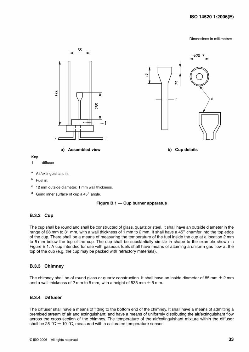
ISO 14520-1:2006(E)
© ISO 2006 – All rights reserved 33
B.3.2 Cup
The cup shall be round and shall be constructed of glass, quartz or steel. It shall have an outside diameter in therange of to , with a wall thickness of to . It shall have a chamfer into the top edgeof the cup. There shall be a means of measuring the temperature of the fuel inside the cup at a location to below the top of the cup. The cup shall be substantially similar in shape to the example shown inFigure B.1. A cup intended for use with gaseous fuels shall have means of attaining a uniform gas flow at thetop of the cup (e.g. the cup may be packed with refractory materials).
B.3.3 Chimney
The chimney shall be of round glass or quartz construction. It shall have an inside diameter of and a wall thickness of to , with a height of .
B.3.4 Diffuser
The diffuser shall have a means of fitting to the bottom end of the chimney. It shall have a means of admitting apremixed stream of air and extinguishant; and have a means of uniformly distributing the air/extinguishant flowacross the cross-section of the chimney. The temperature of the air/extinguishant mixture within the diffusershall be , measured with a calibrated temperature sensor.
Dimensions in millimetres
a) Assembled view b) Cup details
Key
1 diffuser
a Air/extinguishant in.b Fuel in.c outside diameter; wall thickness.d Grind inner surface of cup a angle.
Figure B.1 — Cup burner apparatus
12 mm 1 mm
45◦
28 mm 31 mm 1 mm 2 mm 45◦
2 mm5 mm
85 mm ± 2 mm2 mm 5 mm 535 mm ± 5 mm
25 ◦C ± 10 ◦C
ISO 14520-1:2006(E)
34 © ISO 2006 – All rights reserved
B.3.5 Fuel supply
A liquid fuel supply shall be capable of delivering liquid fuel to the cup while maintaining a fixed, but adjustable,liquid level therein.
A gaseous fuel supply shall be capable of delivering a fuel gas at a controlled and fixed rate to the cup.
B.3.6 Manifold
A manifold shall receive air and extinguishant and deliver them as a single mixed stream to the diffuser.
B.3.7 Air supply
A means for delivering air to the manifold shall allow adjustment of the air flow rate. It shall have a calibratedmeans of measuring the air flow rate.
B.3.8 Extinguishant supply
A means for delivering extinguishant to the manifold shall allow adjustment of the extinguishant flow rate. If themethod according to B.7.2 is used for the determination of the extinguishant concentration, there shall be acalibrated means of measuring the extinguishant flow rate.
B.3.9 Delivery system
The delivery system shall deliver a representative and measurable sample of the agent to the cup burner ingaseous form.
B.4 Requirements for materials
B.4.1 Air
Air shall be clean, dry and oil-free. The oxygen concentration shall be a volume fraction of . Thesource and the oxygen content of the air used shall be recorded.
NOTE “Air” supplied in commercial high-pressure cylinders may have an oxygen content significantly different from .
B.4.2 Fuel
Fuel shall be of a certified type and quality.
B.4.3 Extinguishant
The extinguishant shall be of certified type and meet the specifications of the supplier. Multi-componentextinguishants should be provided premixed. Liquefied extinguishants shall be provided as pure extinguishant,i.e. not pressurized with nitrogen. Prior to commencing tests the composition of the extinguishing gas shall beanalysed.
B.5 Procedure for inflammable liquids
B.5.1 Place the inflammable liquid in the fuel supply reservoir.
B.5.2 Admit fuel to the cup, adjusting the liquid level to within to of the top of the cup.
(20,9 ± 0,5) %
20,9 %
5 mm 10 mm
ISO 14520-1:2006(E)
© ISO 2006 – All rights reserved 35
B.5.3 Adjust the airflow to achieve a flow rate of .
B.5.4 Ignite the fuel.
B.5.5 Allow the fuel to burn for a period of before beginning the flow of extinguishant. During thisperiod, the liquid level in the cup should be adjusted so that the fuel level is within of the top of the cup.
B.5.6 Begin the flow of extinguishant. Increase the extinguishant flow rate in increments until flameextinguishment occurs, and record the extinguishant and air flow rates at extinguishment. The extinguishantflow rate increment should result in an increase in the extinguishant concentration of no more than of theprevious value. Adjustments in the extinguishant flow rate shall be followed by a brief waiting period ( ) toallow the new proportions of extinguishant and air in the manifold to reach the cup position. During this periodthe liquid level shall be maintained within of the top of the cup.
NOTE On an initial run, it is convenient to use relatively large flow increments to ascertain the approximate extinguishantflow required for extinguishment, and on subsequent runs to start at a flow rate close to the critical and to increase the flowby small amounts until extinguishment is achieved.
B.5.7 Determine the extinguishing concentration of the extinguishant in accordance with Clause B.7.
B.5.8 Prior to subsequent tests, remove the fuel from the cup and remove any deposits of residue or soot thatmay be present on the cup.
B.5.9 Repeat steps B.5.2 to B.5.8 for four subsequent tests (five tests in total).
B.5.10 Determine the extinguishing concentration of the extinguishant in accordance with Clause B.7 byestablishing the average from five tests.
B.6 Procedure for inflammable gases
B.6.1 A cup intended for use with gaseous fuels shall have a means of attaining a uniform gas flow at the topof the cup. For example, the cup used for liquid fuels may be packed with refractory materials.
B.6.2 Gaseous fuel shall be from a pressure-regulated supply with a calibrated means of adjusting andmeasuring the gas flow rate.
B.6.3 Adjust the air flow to .
B.6.4 Begin fuel flow to the cup and adjust the flow rate to attain a flame height of approximately . Thefuel temperature shall be .
B.6.5 Ignite the fuel.
B.6.6 Allow the fuel to burn for a period of before beginning flow of extinguishant.
B.6.7 Begin the flow of extinguishant. Increase the extinguishant flow rate in increments until flameextinguishment occurs, and record the air, extinguishant and fuel flow rates at extinguishment. Theextinguishant flow rate increment should result in an increase in the extinguishant concentration of no more than
of the previous value. Adjustments in the extinguishant flow rate are to be followed by a brief waiting period( ) to allow the new proportions of extinguishant and air in the manifold to reach the cup position.
NOTE On an initial run, it is convenient to use relatively large flow increments to ascertain the approximate extinguishantflow required for extinguishment, and on subsequent runs to start at a flow rate close to the critical and to increase the flowby small amounts until extinguishment is achieved.
B.6.8 Upon flame extinguishment, shut off the flow of inflammable gas.
B.6.9 Prior to subsequent tests, remove deposits of residue or soot if present on the cup.
B.6.10 Repeat B.6.3 to B.6.9 for four subsequent tests (five tests in total).
40 l/min
60 s+100 s
1 mm
3 %10 s
1 mm
40 l/min
80 mm25 ◦C ± 10 ◦C
60 s
3 %10 s
ISO 14520-1:2006(E)
36 © ISO 2006 – All rights reserved
B.6.11 Determine the extinguishing concentration of the extinguishant in accordance with Clause B.7 byestablishing the average of the five tests.
B.7 Extinguishant extinguishing concentration
B.7.1 Preferred method
The preferred method for determining the concentration of extinguishant vapour in the extinguishant plus airmixture which just causes flame extinguishment is to use a gas-analysing device, calibrated for theconcentration range of the extinguishant-air mixtures being measured. The device may have continuoussampling capability (e.g. on-line gas analyser) or may be of a type which analyses discrete samples (e.g. gaschromatography). Continuous measurement techniques are preferred.
Alternatively, the remaining concentration of oxygen in the air/extinguishant mixture in the chimney below thecup can be measured with a continuous oxygen-analysis device. The oxygen concentration value is influencedby the extinguishant concentration. The extinguishant concentration is then calculated as follows:
where
the extinguishant concentration, as a volume fraction in percent;
is the oxygen concentration of the air/extinguishant mixture in the chimney, as a volume fraction inpercent;
is the oxygen concentration in the supply air, as a volume fraction in percent.
B.7.2 Alternative method
The extinguishant concentration in the extinguishant plus air mixture may, alternatively, be calculated from themeasured flow rates of the extinguishant and air. Where mass flow rate devices are used, the resulting massflow rates need to be converted to volumetric flow rates as follows:
where
is the volumetric flow rate of gas i, in litres per minute;
is the mass flow rate of gas i, in grams per minute;
is the density of gas i, in grams per litre
Care should be taken to use the actual vapour density. The vapour density of many halogenated hydrocarbonsat ambient temperature and pressure may differ by several percent from that calculated by the ideal gas law.
EXAMPLE The density of HFC-227ea vapour at a pressure of and temperature of is approximately higher than would be calculated for an ideal gas. At a pressure of ( ), however, the difference between theactual vapour density and that calculated for an ideal gas is less than .
Published property data should be used where possible. Estimating techniques may be used when publisheddata are lacking. The source of physical property values used should be recorded in the test report.
cE = 100
(1 − cO
cS
)
cE
cO
cS
Vi = mi/ρi
Vi
mi
ρi
101,3 kPa 295 K 2,4 %6,7 kPa 6,6 %0,2 %
ISO 14520-1:2006(E)
© ISO 2006 – All rights reserved 37
The concentration of extinguishant as a volume fraction in percent, , is calculated as follows:
where
is the extinguishant concentration, as a volume fraction in percent;
is the volumetric flow rate of the air, in litres per minute;
is the volumetric flow rate of the extinguishant, in litres per minute.
B.8 Reporting of results
The following information at least should be included in the report of results:
a) schematic diagram of apparatus, including dimensions and description of materials used;
b) source and assay of the extinguishant, fuel and air;
c) for each test, the fuel temperature at the start of the test, the fuel temperature at the time of extinguishment,and the temperature of the air/extinguishant mixture at extinguishment;
d) extinguishant, gaseous fuel and air flow rates at extinguishment; if method B.7.1 is used, the extinguishantconcentration or the oxygen concentration instead of the extinguishant flow rate;
e) method usyed to determine the extinguishing concentration;
f) extinguishant concentration at extinguishment for each test;
g) measurement error analysis.
c
cE =qext
qair + qext× 100
cE
qair
qext
ISO 14520-1:2006(E)
38 © ISO 2006 – All rights reserved
Annex C(normative)
Fire extinguishment/area coverage fire test procedure for engineered and pre-engineered extinguishing units
C.1 Requirements
C.1.1 An engineered or pre-engineered extinguishing system unit shall mix and distribute its extinguishantand shall totally flood the enclosure when tested in accordance with this test method under the maximumdesign limitations and most severe installation instructions. (See also C.1.2.)
C.1.2 When tested as described in C.4.1, C.4.2 and C.5.2 an extinguishing system unit shall extinguish allvisible flaming within of the end of extinguishant discharge. When tested as described in C.5.1 anextinguishing system unit shall extinguish all visible flaming and prevent re-ignition of the fires after a soaking period (also measured from the end of extinguishant discharge). When tested as described in anextinguishing system unit shall “knock-down” the flames within of the end of extinguishant discharge (thatmeans there are only flames allowed at the top edges of the 2 inner sheets) and extinguish all visible flamingwithin of the end of extinguishant discharge and also prevent re-ignition of the fires after a soakinkperiod (also measured from the end of extinguishant discharge).
C.1.3 The tolerance applicable to dimensions specified in the description of test facilities shall be , if nototherwise stated.
C.2 Type of test
The tests described herein consider the intended use and limitations of the extinguishing system unit, withspecific reference to:
a) the area coverage for each type of nozzle;
b) the operating temperature range of the system;
c) location of nozzles in the protected area;
d) either maximum length and size of piping and number of fittings to each nozzle, or minimum nozzlepressure;
e) maximum discharge time;
f) maximum fill density;
g) extinguishing concentrations for specific fuels.
The tests to be conducted are listed in Table C.1.
30 s10 min
60 s
3 min 10 min
± 5 %
ISO 14520-1:2006(E)
© ISO 2006 – All rights reserved 39
C.3 Extinguishing system
C.3.1 For the extinguishing tests described in C.5.1 and C.5.2, the agent containers shall be conditioned tothe minimum operating temperature specified in the manufacturer's installation instructions.
The extinguishing system shall be assembled as follows:
a) Pre-engineered-type extinguishing system unit — using its maximum piping limitations with respect tonumber of fittings and length of pipe to the discharge nozzles and nozzle configuration(s) as specified in themanufacturer's design and installation instructions.
b) Engineered-type extinguishing system unit — using a piping arrangement that results in the minimumnozzle design pressure at .
C.3.2 For the extinguishing tests described in C.6.1, C.6.2 and C.6.3, the agent containers shall beconditioned at for a minimum period of prior to conducting the test. In these tests the jetenergy from the nozzles shall not influence the development of the fire.
C.3.3 For all tests, the extinguishing system shall to be arranged and dimensioned with regard to thefollowing.
For liquefied extinguishants the time for the discharge of the pre-liquid gas phase plus the two-phase flow shallbe to . Non-superpressurized liquefied extinguishant discharge can be limited by cutting off withappropriate means positioned close to the nozzle, subject to the discharge being between to of thestored agent quantity.
For non-liquefied extinguishants the discharge time shall be to , limited by cutting off the discharge withappropriate means. For the tests, the amount of agent discharged in the test enclosure shall be between and of the stored agent quantity.
C.4 Extinguishing concentration
C.4.1 The extinguishing agent for tests C.5.1, C.5.2, C.6.1, C.6.2 and C.6.3 shall be (i.e. 100/safetyfactor, where the safety factor is 1.3) of the intended minimum design concentration specified in themanufacturer's design and installation instructions at the ambient temperature of within theenclosure. In the tests described in C.5.1 and C.5.2, the same extinguishing concentration shall be used as inthe tests described in C.6.2.
The quantity to reach the concentration within the enclosure can be established using the Equation (1) andEquation (2) (in 7.6.2 and 7.6.3) for liquefied gases and non-liquefied gases respectively.
Table C.1 — Tests to be conducted
Test objective Enclosure size Test fires Reference
Nozzle distribution verification C.5
Nozzle min. height/max. area coverage
To suit nozzle heptane test cans C.5.1
Nozzle max. height heptane test cans C.5.2
no side less than height: to suit nozzle
Extinguishing concentration (a) wood crib C.6.1
no side less than height: at least
(b) heptane pan C.6.2
(c) polymeric sheet C.6.3
(i) PMMA
(ii) Polypropylene
(iii) ABS
� 100 m3
4 m
� 100 m3
4 m3,5 m
20 ◦C ± 2 ◦C
20 ◦C ± 2 ◦C 16 h
8 s 10 s65 % 90 %
50 s 60 s65 %
90 %
76,9 %
20 ◦C ± 2 ◦C
ISO 14520-1:2006(E)
40 © ISO 2006 – All rights reserved
C.4.2 A cold discharge test using the same quantity ( ) of extinguishant shall be conducted in order toverify the actual concentration of extinguishant.
For liquefied extinguishants, the agent concentration shall be measured in the cold discharge test.
For non-liquefied extinguishants, the agent concentration or alternatively the oxygen concentration shall bemeasured. The extinguishant concentration is then calculated from the oxygen concentration using the followingformula:
where
is the extinguishant concentration, as a volume fraction in percent;
is the oxygen concentration measured in the test enclosure, as a volume fraction in percent.
C.5 Nozzle distribution verification tests
C.5.1 Nozzles minimum height/maximum area coverage test
C.5.1.1 Test facility
C.5.1.1.1 Construction
The test enclosure shall meet the following requirements.
a) The area, (see Figure C.1), and height, , of the enclosure shall correspond respectively to themaximum nozzle area coverage and minimum nozzle height specified by the manufacturer.
b) A means of pressure relief shall be provided.
c) Closable openings shall be provided directly above the test cans to allow for venting prior to systemactuation.
d) One baffle shall be installed between the floor and ceiling with the height of the room. It shall be installedhalfway between the nozzle location and the walls of the enclosure (see Figure C.1 for nozzle andFigure C.2 for nozzle). The baffle shall be perpendicular to the direction between nozzle location andwalls of the enclosure (see Figures C.1 and C.2), and shall be of the length of the short wall of theenclosure.
± 2 %
cE = 100
(1 −
[cO
20,95
])
cE
cO
a × b H
360◦
180◦
20 %
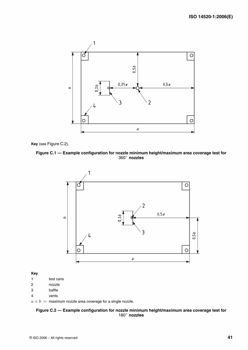
ISO 14520-1:2006(E)
© ISO 2006 – All rights reserved 41
Key (see Figure C.2).
Figure C.1 — Example configuration for nozzle minimum height/maximum area coverage test for nozzles
Key
1 test cans
2 nozzle
3 baffle
4 vents
maximum nozzle area coverage for a single nozzle.
Figure C.2 — Example configuration for nozzle minimum height/maximum area coverage test for nozzles
360◦
a × b =
180◦
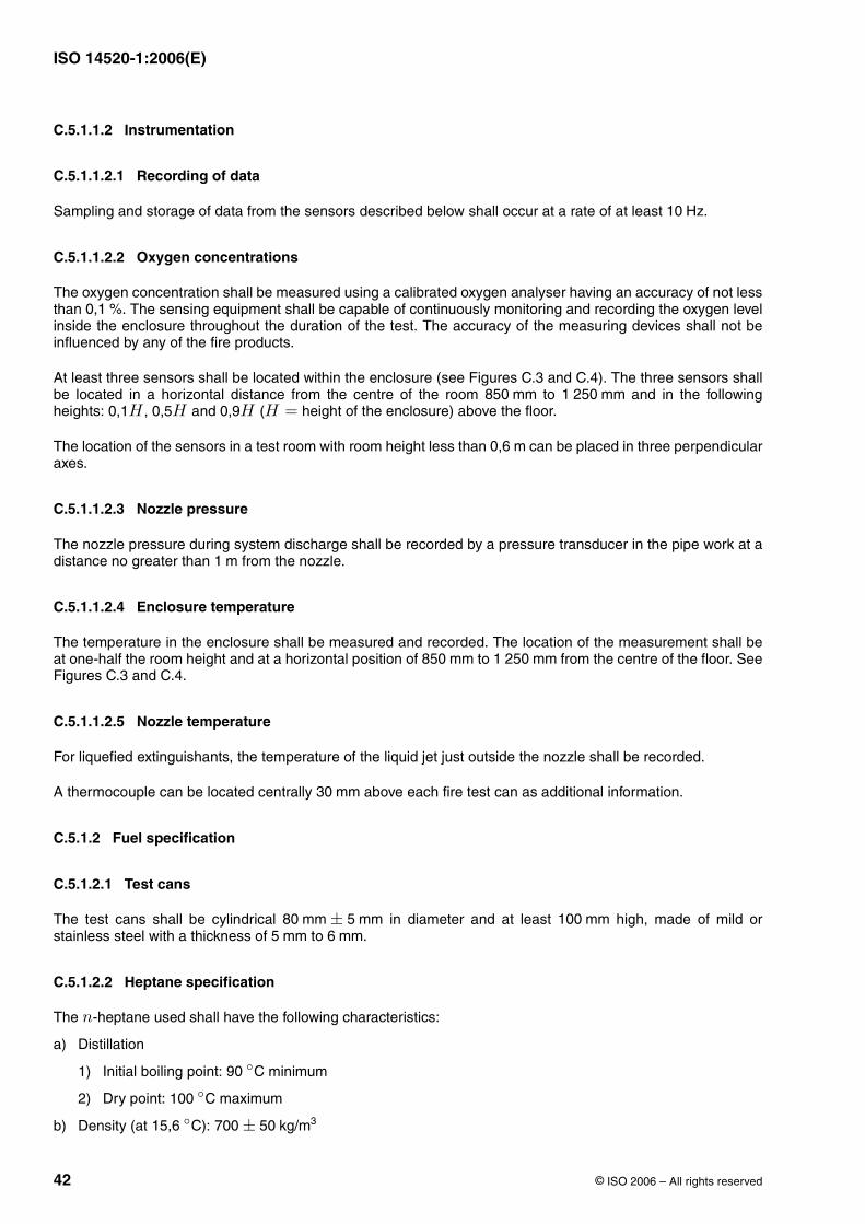
ISO 14520-1:2006(E)
42 © ISO 2006 – All rights reserved
C.5.1.1.2 Instrumentation
C.5.1.1.2.1 Recording of data
Sampling and storage of data from the sensors described below shall occur at a rate of at least .
C.5.1.1.2.2 Oxygen concentrations
The oxygen concentration shall be measured using a calibrated oxygen analyser having an accuracy of not lessthan . The sensing equipment shall be capable of continuously monitoring and recording the oxygen levelinside the enclosure throughout the duration of the test. The accuracy of the measuring devices shall not beinfluenced by any of the fire products.
At least three sensors shall be located within the enclosure (see Figures C.3 and C.4). The three sensors shallbe located in a horizontal distance from the centre of the room to and in the followingheights: , and ( height of the enclosure) above the floor.
The location of the sensors in a test room with room height less than can be placed in three perpendicularaxes.
C.5.1.1.2.3 Nozzle pressure
The nozzle pressure during system discharge shall be recorded by a pressure transducer in the pipe work at adistance no greater than from the nozzle.
C.5.1.1.2.4 Enclosure temperature
The temperature in the enclosure shall be measured and recorded. The location of the measurement shall beat one-half the room height and at a horizontal position of to from the centre of the floor. SeeFigures C.3 and C.4.
C.5.1.1.2.5 Nozzle temperature
For liquefied extinguishants, the temperature of the liquid jet just outside the nozzle shall be recorded.
A thermocouple can be located centrally above each fire test can as additional information.
C.5.1.2 Fuel specification
C.5.1.2.1 Test cans
The test cans shall be cylindrical in diameter and at least high, made of mild orstainless steel with a thickness of to .
C.5.1.2.2 Heptane specification
The -heptane used shall have the following characteristics:
a) Distillation
1) Initial boiling point: minimum
2) Dry point: maximum
b) Density (at ):
10 Hz
0,1 %
850 mm 1 250 mm0,1H 0,5H 0,9H H =
0,6 m
1 m
850 mm 1 250 mm
30 mm
80 mm ± 5 mm 100 mm5 mm 6 mm
n
90 ◦C
100 ◦C
15,6 ◦C 700 ± 50 kg/m3
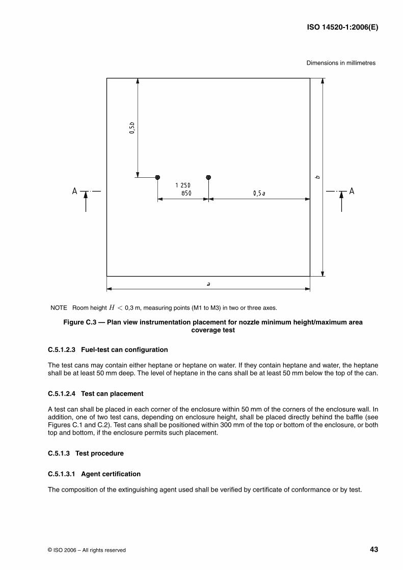
ISO 14520-1:2006(E)
© ISO 2006 – All rights reserved 43
C.5.1.2.3 Fuel-test can configuration
The test cans may contain either heptane or heptane on water. If they contain heptane and water, the heptaneshall be at least deep. The level of heptane in the cans shall be at least below the top of the can.
C.5.1.2.4 Test can placement
A test can shall be placed in each corner of the enclosure within of the corners of the enclosure wall. Inaddition, one of two test cans, depending on enclosure height, shall be placed directly behind the baffle (seeFigures C.1 and C.2). Test cans shall be positioned within of the top or bottom of the enclosure, or bothtop and bottom, if the enclosure permits such placement.
C.5.1.3 Test procedure
C.5.1.3.1 Agent certification
The composition of the extinguishing agent used shall be verified by certificate of conformance or by test.
Dimensions in millimetres
NOTE Room height , measuring points (M1 to M3) in two or three axes.
Figure C.3 — Plan view instrumentation placement for nozzle minimum height/maximum areacoverage test
H < 0,3 m
50 mm 50 mm
50 mm
300 mm
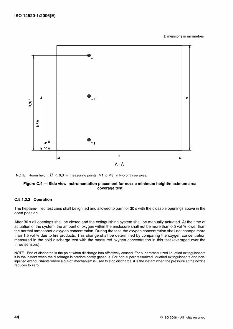
ISO 14520-1:2006(E)
44 © ISO 2006 – All rights reserved
C.5.1.3.2 Operation
The heptane-filled test cans shall be ignited and allowed to burn for with the closable openings above in theopen position.
After all openings shall be closed and the extinguishing system shall be manually actuated. At the time ofactuation of the system, the amount of oxygen within the enclosure shall not be more than 0,5 vol lower thanthe normal atmospheric oxygen concentration. During the test, the oxygen concentration shall not change morethan 1,5 vol due to fire products. This change shall be determined by comparing the oxygen concentrationmeasured in the cold discharge test with the measured oxygen concentration in this test (averaged over thethree sensors).
NOTE End of discharge is the point when discharge has effectively ceased. For superpressurized liquefied extinguishantsit is the instant when the discharge is predominantly gaseous. For non-superpressurized liquefied extinguishants and non-liquified extinguishants where a cut-off mechanism is used to stop discharge, it is the instant when the pressure at the nozzlereduces to zero.
Dimensions in millimetres
NOTE Room height , measuring points (M1 to M3) in two or three axes.
Figure C.4 — Side view instrumentation placement for nozzle minimum height/maximum areacoverage test
H < 0,3 m
30 s
30 s%
%
ISO 14520-1:2006(E)
© ISO 2006 – All rights reserved 45
C.5.1.4 Recording of results
After the required pre-burn period, record the following data for each test:
a) the effective discharge time: i.e. for liquefied extinguishants the time of the pre-liquid gas phase plus thetime of the two-phase flow; for non-liquefied extinguishants the time from opening the container valve(s) tocutting off the discharge; the discharge time for liquefied extinguishants shall be determined by nozzlepressure, nozzle temperature or combination of both;
b) the time required to achieve extinguishment, in seconds; this time shall be determined by visual observationor other suitable means;
c) the total mass of extinguishant discharged into the test enclosure.
C.5.1.5 Determination of distribution performance of the nozzle
All test cans shall be extinguished within of the end of agent discharge.
As an alternative to the use of the heptane steel cans, the concentration of the extinguishing agent (or for non-liquefied gases, the oxygen concentration) can be measured at the locations specified for the steel test cans.The concentration shall be measured at each location and shall be at least the extinguishing concentration, tobe reached after end of discharge time at latest.
C.5.2 Nozzles maximum height test
C.5.2.1 Test facility
C.5.2.1.1 Construction
The test enclosure shall meet the following requirements.
a) The test enclosure shall have a minimum volume of . The floor dimensions shall be at least wideby long. The test enclosure shall have the maximum ceiling height as specified in the manufacturer'sinstallation instructions.
b) A means of pressure relief shall be provided.
c) Closable openings shall be provided directly above the test cans to allow for venting prior to systemactuation.
d) One baffle shall be installed between the floor and ceiling with the height of the room. It shall be installedhalfway between the nozzle location and the walls of the enclosure (see Figure C.1 for nozzle andFigure C.2 for nozzle). The baffle shall be perpendicular to the direction of nozzle discharge, and be
of the length of the short wall of the enclosure.
C.5.2.1.2 Instrumentation
Instrumentation of the enclosure is as described in C.5.1.1.2.
C.5.2.2 Fuel specification
Test fire can construction, configuration, placement and fuel specifications shall be as given in C.5.1.2.
C.5.2.3 Test procedure
C.5.2.3.1 Agent certification
Prior to commencing tests the composition of the extinguishing gas shall be determined by analysis.
30 s
30 s
10 m3 4 m4 m
360◦
180◦
20 %
ISO 14520-1:2006(E)
46 © ISO 2006 – All rights reserved
C.5.2.3.2 Operation
The heptane shall be ignited and allowed to burn for with the closeable openings above in the openposition.
After all openings shall be closed and the extinguishing system shall be manually actuated. At the time ofactuation of the system, the amount of oxygen within the enclosure shall not be more than 0,5 vol lower thanthe normal atmospheric oxygen concentration. During the test, the oxygen concentration shall not change morethan 1,5 vol due to fire products. This change shall be determined by comparing the oxygen concentrationmeasured in the cold discharge test with the oxygen concentration measured in this fire test (averaged values).
C.5.2.3.3 Recording of results
Results shall be recorded as specified in C.5.1.4.
C.5.2.4 Determination of distribution performance of the nozzle
Using the extinguishing concentration for heptane, determined in accordance with C.5.2, all test cans shall beextinguished within of the end of agent discharge.
As an alternative to the use of the heptane steel cans, the concentration of the extinguishing agent (or for non-liquefied gases, the oxygen concentration) can be measured at the locations specified for the steel test cans.The concentration shall be measured at each location and shall be at least the extinguishing concentration, tobe reached after end of discharge time at the latest.
C.6 Extinguishing concentration tests
C.6.1 Wood crib test
C.6.1.1 Test facility
C.6.1.1.1 Construction
The test enclosure shall meet the following requirements.
a) The test enclosure shall have a minimum volume of . The height shall be at least . The floordimensions shall be at least wide by long.
b) A means of pressure relief shall be provided.
c) The temperature in the test enclosure shall be at the beginning of each test and there shallbe enough time between tests for the enclosure to adapt to this temperature.
C.6.1.1.2 Instrumentation
Sampling and storage of data from the sensors described below shall occur at a rate of at least .
C.6.1.1.3 Oxygen concentrations
The oxygen concentration shall be measured by a calibrated oxygen analyser having an accuracy not less than. The sensing equipment shall be capable of continuously monitoring and recording the oxygen level
inside the enclosure throughout the duration of the test. The accuracy of the measuring devices shall not beinfluenced by any of the fire products.
30 s
30 s%
%
30 s
30 s
100 m3 3,5 m4 m 4 m
20 ◦C ± 5 ◦C
10 Hz
0,1 %
ISO 14520-1:2006(E)
© ISO 2006 – All rights reserved 47
At least three sensors shall be located within the enclosure (see Figures C.5 and C.6). One sensor shall belocated at the equivalent height of the top of the test object from the floor, to away from the test object.The other two sensors shall be located at and , with height of the enclosure (see Figures C.5and C.6)
C.6.1.1.4 Nozzle pressure
The nozzle pressure during system discharge shall be recorded by a pressure transducer in the pipe work at adistance not greater than from the nozzle.
C.6.1.1.5 Enclosure temperature
Temperature sensors shall be located centred above the test object and at , and a third sensor atthe equivalent height of the top of the test object from the floor, horizontally to away from the testobject (see Figures C.5 and C.6).
C.6.1.1.6 Nozzle temperature
For liquefied extinguishants, the temperature of the liquid jet just outside the nozzle shall be recorded.
0,6 m 1 m0,1H 0,9H H =
1m
100 mm 0,9H0,6 m 1 m
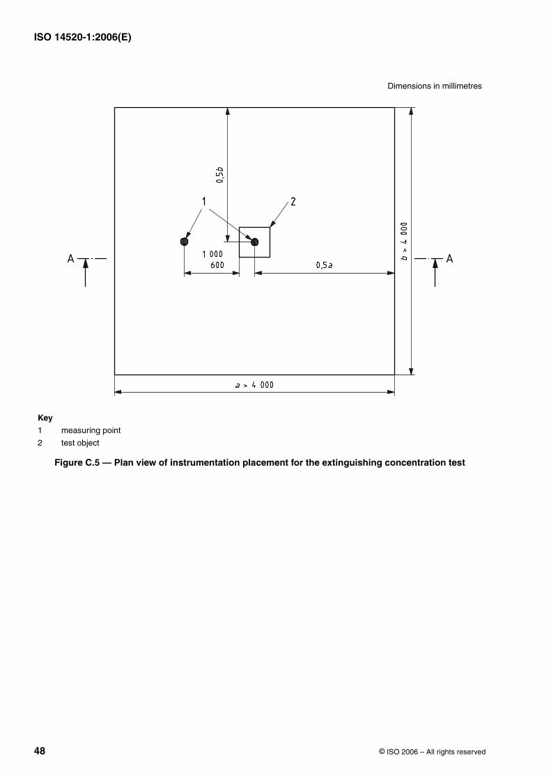
ISO 14520-1:2006(E)
48 © ISO 2006 – All rights reserved
Dimensions in millimetres
Key
1 measuring point
2 test object
Figure C.5 — Plan view of instrumentation placement for the extinguishing concentration test
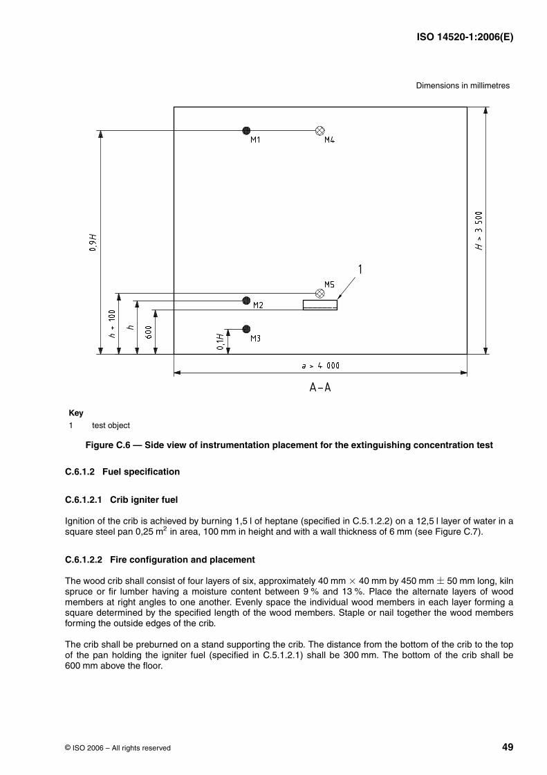
ISO 14520-1:2006(E)
© ISO 2006 – All rights reserved 49
C.6.1.2 Fuel specification
C.6.1.2.1 Crib igniter fuel
Ignition of the crib is achieved by burning of heptane (specified in C.5.1.2.2) on a layer of water in asquare steel pan in area, in height and with a wall thickness of (see Figure C.7).
C.6.1.2.2 Fire configuration and placement
The wood crib shall consist of four layers of six, approximately by long, kilnspruce or fir lumber having a moisture content between and . Place the alternate layers of woodmembers at right angles to one another. Evenly space the individual wood members in each layer forming asquare determined by the specified length of the wood members. Staple or nail together the wood membersforming the outside edges of the crib.
The crib shall be preburned on a stand supporting the crib. The distance from the bottom of the crib to the topof the pan holding the igniter fuel (specified in C.5.1.2.1) shall be . The bottom of the crib shall be
above the floor.
Dimensions in millimetres
Key
1 test object
Figure C.6 — Side view of instrumentation placement for the extinguishing concentration test
1,5 l 12,5 l0,25 m2 100 mm 6 mm
40 mm × 40 mm 450 mm ± 50 mm9 % 13 %
300 mm600 mm
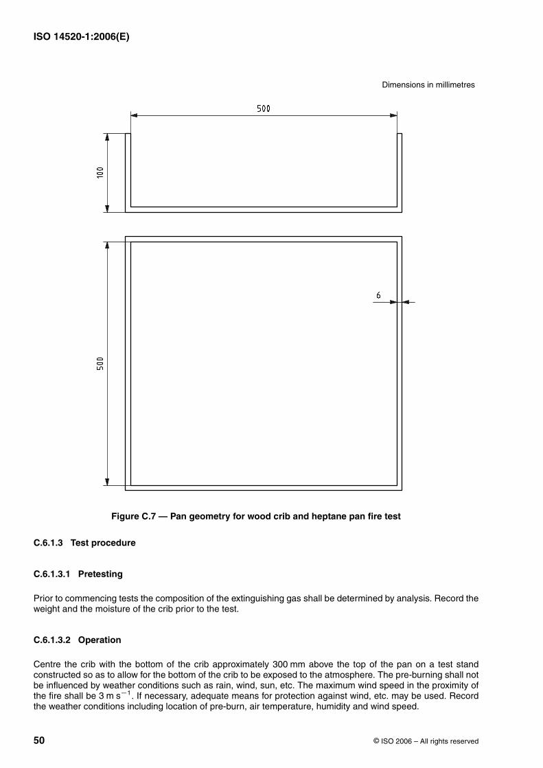
ISO 14520-1:2006(E)
50 © ISO 2006 – All rights reserved
C.6.1.3 Test procedure
C.6.1.3.1 Pretesting
Prior to commencing tests the composition of the extinguishing gas shall be determined by analysis. Record theweight and the moisture of the crib prior to the test.
C.6.1.3.2 Operation
Centre the crib with the bottom of the crib approximately above the top of the pan on a test standconstructed so as to allow for the bottom of the crib to be exposed to the atmosphere. The pre-burning shall notbe influenced by weather conditions such as rain, wind, sun, etc. The maximum wind speed in the proximity ofthe fire shall be . If necessary, adequate means for protection against wind, etc. may be used. Recordthe weather conditions including location of pre-burn, air temperature, humidity and wind speed.
Dimensions in millimetres
Figure C.7 — Pan geometry for wood crib and heptane pan fire test
300 mm
3 m s−1
ISO 14520-1:2006(E)
© ISO 2006 – All rights reserved 51
Ignite the heptane and allow the crib to burn freely. The crib shall be allowed to burn freely for a total pre-burntime of .
At the time of actuation of the system, the amount of oxygen within the enclosure at the level of the crib shall notbe more than 0,5 vol lower than the normal atmospheric oxygen concentration. During the test, the oxygenconcentration shall not change more than 1,5 vol due to fire products. This change shall be determined bycomparing the oxygen concentration measured in the cold discharge test with the oxygen concentrationmeasured in this fire test (averaged values). If the start oxygen concentration in the fire tests and the colddischarge test are different, this shall be taken into account while comparing the oxygen concentrations.
From the end of system discharge, the enclosure shall remain sealed for a total of . After the soak period,remove the crib from the enclosure and observe whether sufficient fuel remains to sustain combustion and lookfor signs of re-ignition. The following shall be recorded:
a) presence and location of burning embers-,
b) whether or not the glowing embers or crib re-ignites;
c) weight of the crib after the test.
If necessary, amend the extinguishant concentration and repeat the experimental programme until threesuccessive, successful extinguishments are achieved.
C.6.1.3.3 Results recording
After the required pre-burn period, record the following data for each test:
a) the effective discharge time: i.e. for liquefied extinguishants the time of the pre-liquid gas phase plus thetime of the two phase flow; for non-liquefied extinguishants the time from opening the container valve(s) tocutting off the discharge; the discharge time for liquefied extinguishants has to be determined by nozzlepressure, nozzle temperature or combination of both;
b) the time required to achieve extinguishment, in seconds; this time shall be determined by visual observationor other suitable means;
c) the total mass of extinguishant discharged into the test enclosure;
d) the soaking time (time from the end of system discharge until the opening of the test enclosure);
e) the temperature profile of the wood crib.
NOTE End of discharge is the point when discharge has effectively ceased. For superpressurized liquefied extinguishantsit is the instant when the discharge is predominantly gaseous. For non-superpressurized liquefied extinguishants and non-liquified extinguishants where a cut-off mechanism is used to stop discharge, it is the instant when the pressure at the nozzlereduces to zero.
C.6.1.4 Determination of design extinguishant concentration
The laboratory extinguishant concentration is that concentration which achieves satisfactory extinguishment ofthe fire over three successive tests (no re-ignition or existence of burning embers after after end ofdischarge). Alternatively, three successful, non-successive tests may be used providing the highestconcentration is taken (i.e. the test with the greatest mass of agent discharged and the longest discharge time).The design concentration is the laboratory concentration multiplied by an appropriate 'safety factor'.
C.6.2 Heptane pan test
C.6.2.1 Test facility
C.6.2.1.1 Construction
Construction of the enclosure is as described in C.6.1.1.1.
6 min +100 s
%%
10 min
10 min
ISO 14520-1:2006(E)
52 © ISO 2006 – All rights reserved
C.6.2.1.2 Instrumentation
Instrumentation of the enclosure is as described in C.6.1.1.2 to C.6.1.1.6.
C.6.2.2 Fuel specification
C.6.2.2.1 Heptane
The heptane is as specified in C.5.1.2.2.
C.6.2.2.2 Fire configuration and placement
The fire shall be in a square steel pan of , high with a wall thickness of as specified inC.6.1.2.1. The test pan shall contain of heptane. The resulting heptane surface is then below thetop of the pan.
The steel pan shall be located in the centre of the test enclosure with the bottom above the floor of thetest enclosure.
C.6.2.3 Test procedure
C.6.2.3.1 Pretesting
Prior to commencing tests the composition of the extinguishing gas shall be determined by analysis.
C.6.2.3.2 Operation
The heptane shall be ignited and allowed to burn for .
After all openings shall be closed and the extinguishing system shall be manually actuated. At the time ofactuation of the system, the amount of oxygen within the enclosure shall not be more than 0,5 vol lower thanthe normal atmospheric oxygen concentration. During the test, the oxygen concentration shall not change morethan 1,5 vol due to fire products. This change shall be determined by comparing the oxygen concentrationmeasured in the cold discharge test with the oxygen concentration measured in this fire test (averaged values).
If necessary, amend the extinguishant concentration and repeat the experimental programme until threesuccessive, successful extinguishments are achieved.
C.6.2.3.3 Agent certification
The composition of the extinguishing agent shall be verified by a certificate of conformance or by test.
C.6.2.3.4 Recording of results
Results shall be recorded as specified in C.6.1.3.3 with the exception of e).
C.6.2.4 Determination of design extinguishant concentration
The laboratory extinguishant concentration is that concentration which achieves satisfactory extinguishment ofthe fire over three successive tests (no flaming after the end of extinguishant discharge). Alternatively,three successful, non-successive tests may be used providing the highest concentration is taken (i.e. the testwith the greatest mass of agent discharged and the longest discharge time). The design concentration is thelaboratory concentration multiplied by an appropriate 'safety factor'.
0,25 m2 100 mm 6 mm12,5 l 50 mm
600 mm
30 s
30 s%
%
30 s
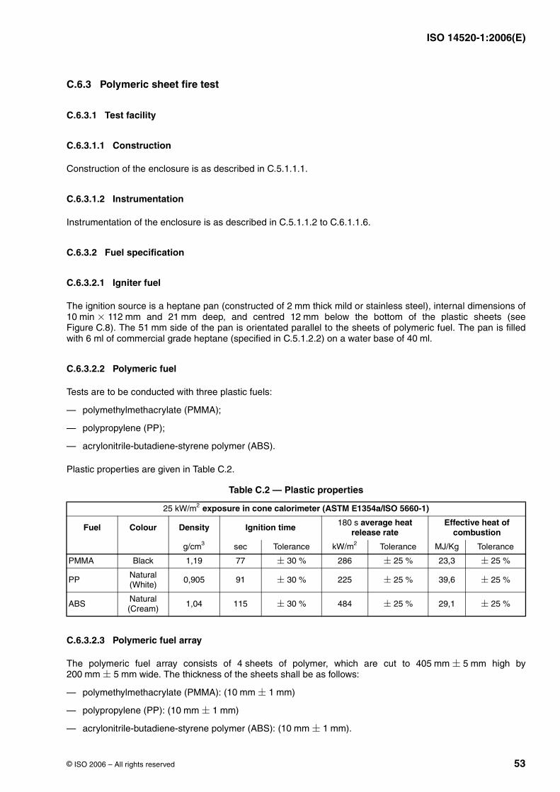
ISO 14520-1:2006(E)
© ISO 2006 – All rights reserved 53
C.6.3 Polymeric sheet fire test
C.6.3.1 Test facility
C.6.3.1.1 Construction
Construction of the enclosure is as described in C.5.1.1.1.
C.6.3.1.2 Instrumentation
Instrumentation of the enclosure is as described in C.5.1.1.2 to C.6.1.1.6.
C.6.3.2 Fuel specification
C.6.3.2.1 Igniter fuel
The ignition source is a heptane pan (constructed of thick mild or stainless steel), internal dimensions of and deep, and centred below the bottom of the plastic sheets (see
Figure C.8). The side of the pan is orientated parallel to the sheets of polymeric fuel. The pan is filledwith 6 ml of commercial grade heptane (specified in C.5.1.2.2) on a water base of .
C.6.3.2.2 Polymeric fuel
Tests are to be conducted with three plastic fuels:
— polymethylmethacrylate (PMMA);
— polypropylene (PP);
— acrylonitrile-butadiene-styrene polymer (ABS).
Plastic properties are given in Table C.2.
C.6.3.2.3 Polymeric fuel array
The polymeric fuel array consists of 4 sheets of polymer, which are cut to high by wide. The thickness of the sheets shall be as follows:
— polymethylmethacrylate (PMMA): ( )
— polypropylene (PP): ( )
— acrylonitrile-butadiene-styrene polymer (ABS): ( ).
Table C.2 — Plastic properties
exposure in cone calorimeter (ASTM E1354a/ISO 5660-1)
Fuel Colour Density Ignition time average heat release rate
Effective heat of combustion
sec Tolerance Tolerance Tolerance
PMMA Black 1,19 77 286 23,3
PP Natural (White)
0,905 91 225 39,6
ABSNatural (Cream)
1,04 115 484 29,1
2 mm10 min × 112 mm 21 mm 12 mm
51 mm40 ml
25 kW/m2
180 s
g/cm3 kW/m2 MJ/Kg
± 30 % ± 25 % ± 25 %
± 30 % ± 25 % ± 25 %
± 30 % ± 25 % ± 25 %
405 mm ± 5 mm200 mm ± 5 mm
10 mm ± 1 mm
10 mm ± 1 mm
10 mm ± 1 mm
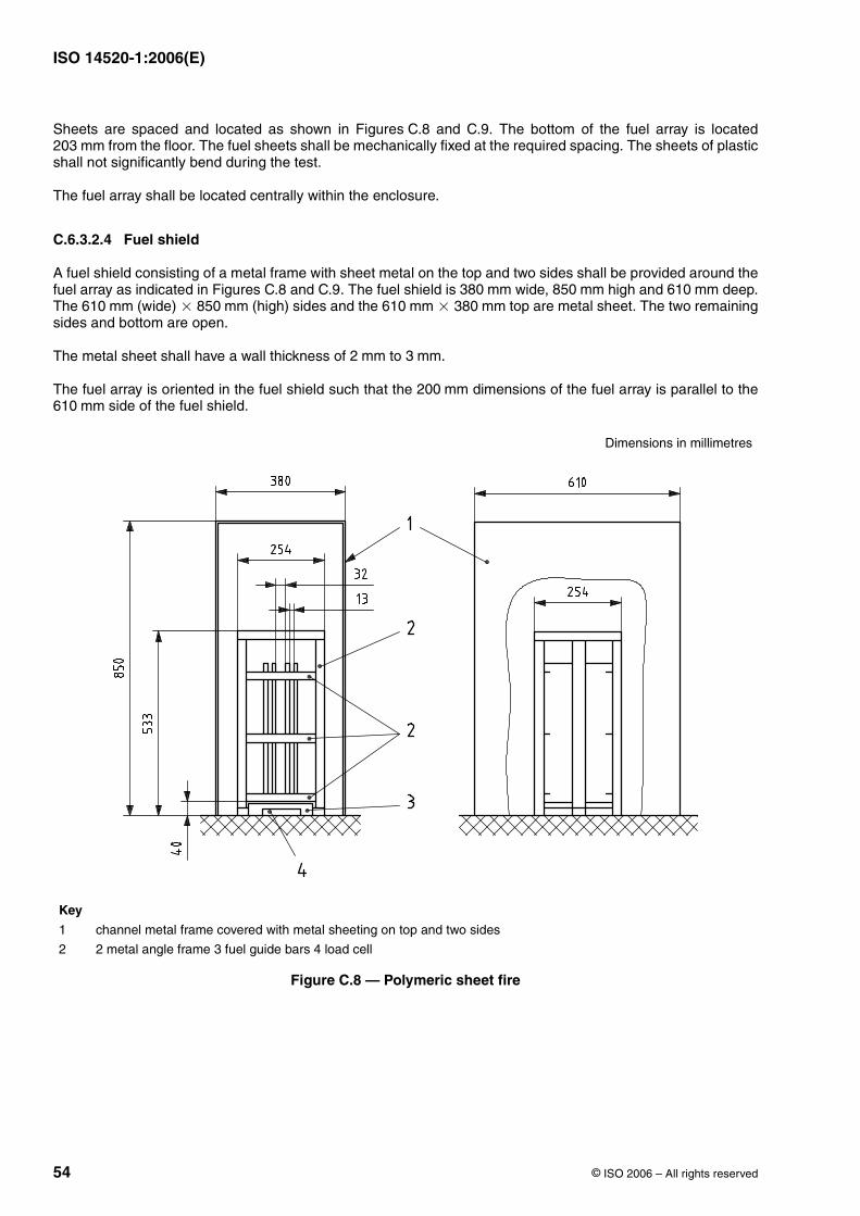
ISO 14520-1:2006(E)
54 © ISO 2006 – All rights reserved
Sheets are spaced and located as shown in Figures C.8 and C.9. The bottom of the fuel array is located from the floor. The fuel sheets shall be mechanically fixed at the required spacing. The sheets of plastic
shall not significantly bend during the test.
The fuel array shall be located centrally within the enclosure.
C.6.3.2.4 Fuel shield
A fuel shield consisting of a metal frame with sheet metal on the top and two sides shall be provided around thefuel array as indicated in Figures C.8 and C.9. The fuel shield is wide, high and deep.The (wide) (high) sides and the top are metal sheet. The two remainingsides and bottom are open.
The metal sheet shall have a wall thickness of to .
The fuel array is oriented in the fuel shield such that the dimensions of the fuel array is parallel to the side of the fuel shield.
Dimensions in millimetres
Key
1 channel metal frame covered with metal sheeting on top and two sides
2 2 metal angle frame 3 fuel guide bars 4 load cell
Figure C.8 — Polymeric sheet fire
203 mm
380 mm 850 mm 610 mm610 mm × 850 mm 610 mm × 380 mm
2 mm 3 mm
200 mm610 mm
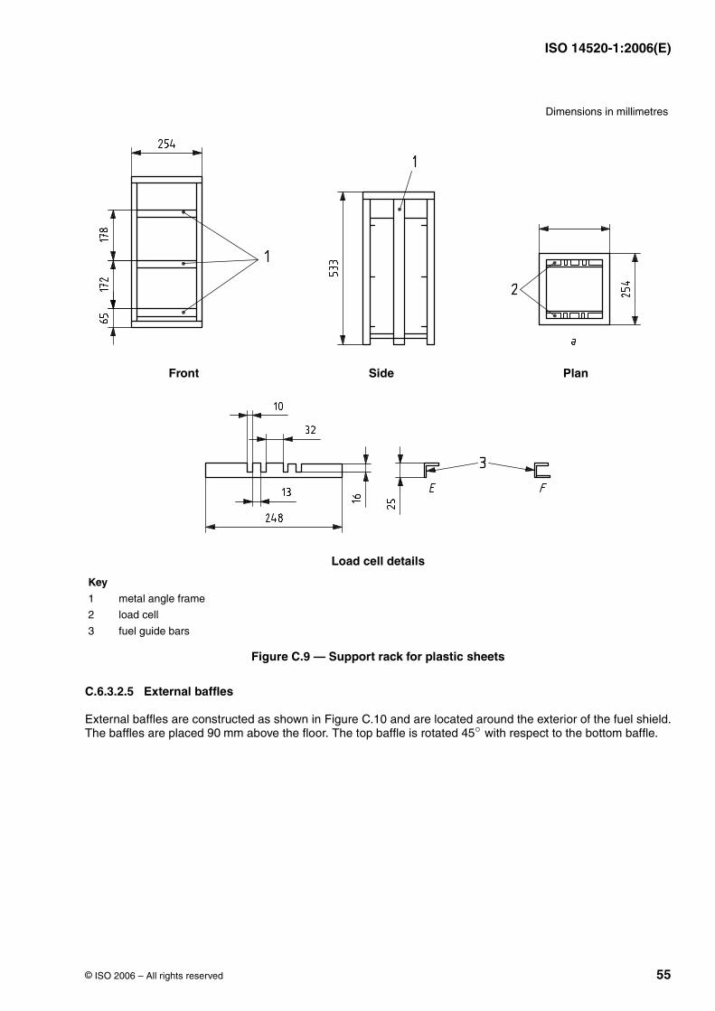
ISO 14520-1:2006(E)
© ISO 2006 – All rights reserved 55
C.6.3.2.5 External baffles
External baffles are constructed as shown in Figure C.10 and are located around the exterior of the fuel shield.The baffles are placed above the floor. The top baffle is rotated with respect to the bottom baffle.
Dimensions in millimetres
Front Side Plan
Load cell details
Key
1 metal angle frame
2 load cell
3 fuel guide bars
Figure C.9 — Support rack for plastic sheets
90 mm 45◦
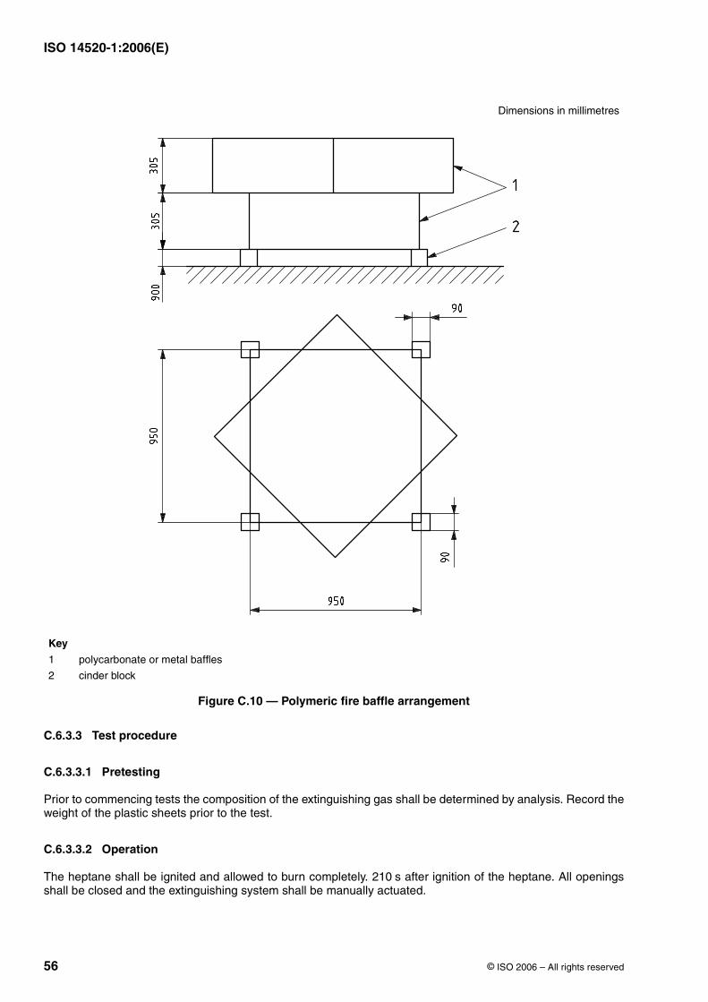
ISO 14520-1:2006(E)
56 © ISO 2006 – All rights reserved
C.6.3.3 Test procedure
C.6.3.3.1 Pretesting
Prior to commencing tests the composition of the extinguishing gas shall be determined by analysis. Record theweight of the plastic sheets prior to the test.
C.6.3.3.2 Operation
The heptane shall be ignited and allowed to burn completely. after ignition of the heptane. All openingsshall be closed and the extinguishing system shall be manually actuated.
Dimensions in millimetres
Key
1 polycarbonate or metal baffles
2 cinder block
Figure C.10 — Polymeric fire baffle arrangement
210 s
ISO 14520-1:2006(E)
© ISO 2006 – All rights reserved 57
At the time of actuation of the system, the amount of oxygen within the enclosure at the level of the fuel shall notbe more than 0,5 vol lower than the normal atmospheric oxygen concentration. During the test, the oxygenconcentration shall not change more than 1,5 vol due to fire products. This change shall be determined bycomparing the oxygen concentration measured in the cold discharge test with the oxygen concentrationmeasured in this fire test (averaged values).
The enclosure shall remain sealed for a total of after end of discharge. After the soak period, ventilatethe enclosure and observe whether sufficient fuel remains to sustain combustion and look for signs of re-ignition.
The following shall be recorded:
a) presence and location of burning fuel;
b) whether or not the fire re-ignites;
c) weight of the fire structure after the test.
If necessary, amend the extinguishant concentration and repeat the experimental programme until threesuccessive, successful extinguishments are achieved.
C.6.3.3.3 Recording of results
After the required pre-burn period, record the following data for each test:
a) the effective discharge time: i.e. for liquefied extinguishants the time of the pre-liquid gas phase plus thetime of the two-phase flow; for non-liquefied extinguishants the time from opening the container valve(s) tocutting off the discharge; the discharge time for liquefied extinguishants shall be determined by nozzlepressure, nozzle temperature or a combination of both;
b) the time to achieve “knock-down” of the flames, that means the time when there are only flames at the topedges of the two inner plastic sheets, in seconds; this time shall be determined by visual observation orother suitable means;
c) the time required to achieve extinguishment, in seconds; this time shall be determined by visual observationor other suitable means;
d) the total mass of extinguishant discharged into the test enclosure;
e) the soaking time (time from the end of system discharge until the opening of the test enclosure).
NOTE End of discharge is the point when discharge has effectively ceased. For superpressurized liquefied extinguishantsit is the instant when the discharge is predominantly gaseous. For non-superpressurized liquefied extinguishants and non-liquefied extinguishants where a cut-off mechanism is used to stop discharge, it is the instant when the pressure at thenozzle reduces to zero.
C.6.3.4 Determination of design extinguishant concentration
The extinguishing concentration for each fuel is that concentration which achieves satisfactory extinguishmentof the fire over three successive tests (only flames at the top edges of the 2 inner plastic sheets at afterend of discharge, no flaming after end of discharge and no re-ignition after after end of discharge).Alternatively, three successful, non-successive tests may be used providing the highest concentration is taken(i.e. the test with the greatest mass of agent discharged and the longest discharge time).
The minimum design concentration is the highest of the laboratory concentrations for the three fuels(see C.6.3.2.2) multiplied by an appropriate 'safety factor'.
%%
10 min
180 s60 s 10 min
ISO 14520-1:2006(E)
58 © ISO 2006 – All rights reserved
Annex D(normative)
Method of evaluating inerting concentration of a fire extinguishant
D.1 Scope
This annex specifies a method for determining the inerting or inhibiting concentration of the extinguishant basedon inflammability diagram data on ternary systems (fuel, extinguishant, air).
D.2 Principle
Fuel/extinguishant/air mixture at a pressure of ( or ) is ignited using a gap spark and therise in pressure is measured.
D.3 Apparatus
D.3.1 Test vessel, spherical, with a capacity of , with inlet and vent ports, thermocouple andpressure transducer, as shown in Figure D.1.
D.3.2 Igniter, for nominal resistance of comprising four graphite rods (“H” pencil leads) held togetherby two wire ties at either end, leaving a gap between the ties of approximately .
D.3.3 Capacitors, two , , wired in series with the igniter.
D.3.4 Internal mixing fan, suitable to withstand the temperature and overpressure of an explosion.
D.4 Procedure
D.4.1 The sphere (D.3.1) and components should be at nominal room temperature ( ). Note anytemperature difference outside of this range.
D.4.2 Connect the pressure transducer to a suitable recording device to measure the pressure rise in the testvessel to the nearest .
D.4.3 Evacuate the test vessel (D.3.1).
D.4.4 Admit the extinguishant up to the concentration required by the partial pressure method and, if a liquid,allow time for evaporation to occur.
D.4.5 Admit fuel vapour and air [ relative humidity] up to the concentration required by the partialpressure method until the pressure in the vessel is ( or ).
D.4.6 Turn on the fan (D.3.4) and allow to mix for . Turn off the fan and wait for for the mixture toreach quiescent conditions.
D.4.7 Charge the capacitors (D.3.3) to a potential of to (d.c.), producing a stored energy of to .
D.4.8 Close the switch and discharge the capacitors.
NOTE The capacitor discharge current results in ionization of the graphite rod surface causing a corona spark to jumpacross the connector gap.
1 atm 1 bar 14,7 psia
7,9 l ± 0,25 l
1 ohm3 mm
525 mF 450 V
22 ◦C ± 3 ◦C
70 Pa
(50 ± 5) %1 atm 1 bar 14,7 psia
1 min 1 min
720 V 740 V 68 J70 J
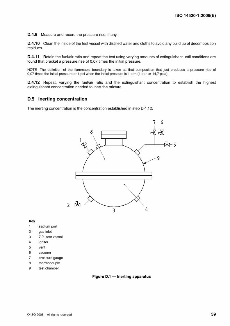
ISO 14520-1:2006(E)
© ISO 2006 – All rights reserved 59
D.4.9 Measure and record the pressure rise, if any.
D.4.10 Clean the inside of the test vessel with distilled water and cloths to avoid any build up of decompositionresidues.
D.4.11 Retain the fuel/air ratio and repeat the test using varying amounts of extinguishant until conditions arefound that bracket a pressure rise of 0,07 times the initial pressure.
NOTE The definition of the flammable boundary is taken as that composition that just produces a pressure rise of0,07 times the initial pressure or 1 psi when the initial pressure is ( or ).
D.4.12 Repeat, varying the fuel/air ratio and the extinguishant concentration to establish the highestextinguishant concentration needed to inert the mixture.
D.5 Inerting concentration
The inerting concentration is the concentration established in step D.4.12.
Key
1 septum port
2 gas inlet
3 test vessel
4 igniter
5 vent
6 vacuum
7 pressure gauge
8 thermocouple
9 test chamber
Figure D.1 — Inerting apparatus
1 atm 1 bar 14,7 psia
7,9 l
ISO 14520-1:2006(E)
60 © ISO 2006 – All rights reserved
Annex E(normative)
Door fan test for determining of minimum hold time
E.1 Scope
This annex contains information for establishing the integrity of rooms and enclosures with respect tomaintaining the extinguishant concentration for the relevant period (hold time). It includes details of testing andassumes that air-handling plant will not be operating during the hold time.
This procedure cannot be used to predict what extinguishant concentrations may develop in adjoining spaces.
This procedure is only suitable providing:
a) an adequate return air path exists (see E.2.4.2 and E.2.7.1.3);
b) the fan unit(s) can develop an enclosure pressure of (this is a function of the size of the enclosure, itsintegrity, and the number and capacities of the fans (see E.2.2.1 and E.2.7.4.3).
The calculation procedures used are suitable for both heavier than air extinguishants and extinguishants thatare lighter than air. The hold time calculation models, for enclosures without continuous mixing, assume that theenclosure is either a standard enclosure or a non-standard enclosure. A standard enclosure is one that has auniform horizontal cross sectional area with horizontal upper and lower boundaries. A non-standard enclosureis one with a non-uniform horizontal cross sectional area and/or sloping upper and/or lower boundaries.
NOTE For gas/air mixtures heavier than air, the calculation procedures have been verified by comparison of calculationresults from door fan testing with hold times from real flooding tests. This has not yet been done for gas mixtures lighter thanair.
E.2 Test for determination of predicted hold time
E.2.1 Principle
A fan is temporarily located within an access opening to pressurize and depressurize the enclosure. A series ofpressure and airflow measurements is made from which the leakage characteristics of the enclosure areestablished.
The predicted hold time is calculated using these leakage characteristics on the following assumptions:
a) that leakage occurs under the worst conditions, i.e. when one half of the effective leakage area is at themaximum enclosure height, and the other half (the lower leakage area) is at the lowest point in theenclosure;
b) the direction of flow through the enclosure, during the hold time, is downwards for extinguishants heavierthan air, and upwards for extinguishants lighter than air;
c) that all leak flow is one-dimensional, i.e. ignoring stream functions;
d) that flow through any particular leak area is either into or out of the enclosure and respectively either fromor into an infinitely large space;
e) that the enclosure and surroundings are at a temperature of , and atmospheric pressure is absolute.
25 Pa
20 ◦C 1,013 bar
ISO 14520-1:2006(E)
© ISO 2006 – All rights reserved 61
E.2.2 Apparatus
E.2.2.1 Fan unit, consisting of a frame which will fit into and seal an access opening in the enclosure, and oneor more variable speed fans, with low flow facilities, capable of giving a differential pressure of not less than
across the enclosure boundary.
E.2.2.2 Pressure measuring devices, two in number, one to measure enclosure differential pressure andone to measure fan flow pressure.
E.2.2.3 Flexible tubing, for connecting the pressure measuring devices.
E.2.2.4 Chemical smoke pencils and/or smoke generator.
E.2.2.5 Thermometers, two in number, for measuring ambient temperatures.
E.2.2.6 Signs, reading “DO NOT OPEN — PRESSURE TEST IN PROGRESS” and “DO NOT CLOSE —PRESSURE TEST IN PROGRESS”, displayed during the test operation.
NOTE Additional apparatus, such as measuring tapes, barometer for measuring atmospheric pressure, torches, ladders,tools to remove floor and ceiling tiles, computer or other calculating device, camera, may be necessary or convenient.
E.2.3 Calibration and accuracy of apparatus
E.2.3.1 Fan unit
The fan unit (E.2.2.1) shall be calibrated at the intervals and by the method recommended by the manufacturer.Records shall be kept and also copies of the appropriate calibration certificates. The flow rate shall be accurateto of the measured value.
E.2.3.2 Pressure measuring devices
The pressure measuring devices (E.2.2.2) shall be accurate to and shall be calibrated at regularintervals. Records shall be maintained and where appropriate calibration certificates. The pressure measuringdevice to measure the fan flow pressure may have a different accuracy as long as the requirements for theaccuracy of the flow rate (see E.2.3.1) is fulfilled. The atmospheric pressure measurement shall be accurate to
.
If inclined manometers are used, change the fluid at the intervals recommended by the manufacturer. Level andzero inclined manometers before each test.
E.2.3.3 Temperature measuring devices
Temperature measuring devices shall be accurate to
E.2.4 Preliminary preparation
E.2.4.1 Obtain a description of air-handling equipment and extinguishant extraction systems, serving theenclosure and its surroundings, from the user.
E.2.4.2 Check for the following:
a) raised platform floors and false ceiling spaces;
b) visually obvious leaks in the enclosure;
c) adequate return paths outside the enclosure between all leaks and the fan unit;
25 Pa
± 5 %
± 1 Pa
± 100 Pa
± 1 ◦C
ISO 14520-1:2006(E)
62 © ISO 2006 – All rights reserved
d) conflicting activities in and around the enclosure;
e) leakage areas in the hold time condition by visually checking the door closure, or other opening selected formounting the fan unit.
E.2.4.3 Provide the following information to the user:
a) description of the test;
b) time required to complete the test;
c) what assistance will be needed from the user's staff;
d) information on any necessary disturbance to the building or its services during the test; e.g. removal of flooror ceiling tiles, shutdown of air handling systems, holding doors open and/or shut.
E.2.5 Evaluation of enclosure
E.2.5.1 General
Obtain or prepare a sketch plan showing the enclosure and its surroundings, the location of door and otheropenings through which air will flow during the test, and the location of any ducts penetrating the enclosure, andany dampers in the ducts. Show the status (i.e. whether open, closed, on, off during the hold time) of each door,hatch, damper and other significant items (e.g. fans), and which access opening(s) is (are) to be used for the fanunit.
Show the location of floor and sink drains.
E.2.5.2 Mixing during hold time
Enclosures with continuous mixing are enclosures in which there will be continuous good mixing e.g. due tostrong heat sources or recirculating air handling equipment, so that an interface does not form and a uniformextinguishant concentration is maintained throughout the enclosure during the hold time.
Enclosures without continuous mixing are enclosures in which there is partial or no mixing during the hold time,so that an interface forms between the extinguishant/air mixture and the incoming air.
If it is uncertain whether the enclosure is one with or without continuous mixing, then perform the hold timecalculations for both cases. Use the lower of the two hold time values.
E.2.6 Measurement of enclosure
E.2.6.1 Standard enclosures without continuous mixing
Standard enclosures are those with a uniform horizontal cross sectional area and horizontal upper and lowerboundaries. Measure the protected enclosure as necessary and record the following:
a) the overall height of the protected enclosure, ;
b) the required protected height, ;
c) the net volume of the protected enclosure, .
Ho
H
V
ISO 14520-1:2006(E)
© ISO 2006 – All rights reserved 63
E.2.6.2 Non-standard enclosures without continuous mixing
Non-standard enclosures are those with non- uniform horizontal cross sectional area, such as enclosures withnon-horizontal upper and/or lower boundaries. Measure the protected enclosure as necessary and record thefollowing:
a) the overall height of the protected enclosure from its lowest to its highest point, ;
b) the required protected height from the lowest point in the enclosure, ;
c) the net volume of the protected enclosure, ;
d) the horizontal cross-sectional area, , at various heights, sufficient to determine its variation with height sothat and can be evaluated using Equations (E.24) and (E.25). See E.2.8.9.3.
E.2.6.3 Enclosures of any shape with continuous mixing
Measure the protected enclosure as necessary and record the following:
a) the overall height of the protected enclosure from its lowest to its highest point, ;
b) the net volume of the protected enclosure, .
E.2.6.4 Opening for mounting the fan unit
If the door or other closure, replaced by the fan unit for the purpose of test, has significant measurable leakageopenings in the hold time condition then these should be measured and recorded.
E.2.7 Test procedure
E.2.7.1 Preparation
E.2.7.1.1 Advise supervisory personnel in the area of the test.
E.2.7.1.2 Remove papers and objects likely to be disturbed by the air stream from the fan.
E.2.7.1.3 Block open sufficient doors outside the enclosure envelope to provide an adequate return path for airbetween the fan unit and the enclosure boundaries while correcting any breach of any requirements of thefacility, including requirements for security, fire protection and environmental boundaries.
E.2.7.1.4 Using the sketch plan (see E.2.5) set the enclosure air-handling equipment and extinguishantextraction systems to the state they would be in during the hold time, except that:
a) recirculating air-handling equipment without fresh air make-up or exhaust which does not give a biaspressure across the enclosure boundary or otherwise preclude accurate testing, and which would be shutdown on extinguishant discharge, may be left operating during the test if this is needed to avoid temperaturebuild-up in equipment such as computers;
b) air-handling equipment, with fresh air make up or exhaust, which would continue to operate onextinguishant discharge should be shut down as it may create excessive bias pressure during the integritytest.
E.2.7.1.5 Post the appropriate signs on doors (see E.2.2.6).
E.2.7.1.6 Open doors and remove floor or ceiling tiles within the extinguishant-protected portions of theenclosure envelope so that the extinguishant-protected volume is treated as one space. Do not remove falseceiling tiles if the volume above the false ceiling is not protected with extinguishant.
Ho
H
V
AVe dVe
Ho
V
ISO 14520-1:2006(E)
64 © ISO 2006 – All rights reserved
CAUTION — The removal of raised floor tiles creates a serious safety hazard. Appropriate precautionsshould be taken.
E.2.7.1.7 Set all doors and windows and other openings in the enclosure envelope to the state they would beduring the hold time.
E.2.7.1.8 Check that liquid traps in the floor and sink drains are sealed with liquid.
E.2.7.1.9 Record the conditions (enclosure, surroundings and services) during the fan test.
E.2.7.2 Setting up the door fan unit
E.2.7.2.1 Set up the fan unit in an access opening leading from the enclosure into the largest volume ofbuilding space which will complete the air flow path from the fan, via the enclosure, leaks, and building spaceback to the fan.
E.2.7.2.2 Gently blow into, or suck from, the flexible tubing so that the readings of the pressure measuringdevices traverse the full scale. Hold the maximum reading for not less than .
Release the pressure and zero the devices.
E.2.7.2.3 Connect the enclosure differential pressure measuring device and the fan pressure measuringdevice. Ensure that the open ends of the flexible tubing near the fan unit are away from its air stream path andany other air flows which might affect the readings.
E.2.7.2.4 Use the fan(s) to raise or lower the pressure of the enclosure to the maximum safe pressureobtainable. Check all dampers with smoke and ensure that they are closed properly. Check doors and hatchesand ensure correct closure. Inspect the wall perimeter (above and below any false floor) and the floor slab forany major leaks and note their size and location.
E.2.7.2.5 Ensure that there will be no pressure differential between the area of the fan outside the enclosure,and along the return air paths around the boundary of the enclosure under test. This may be done visually or bypressure measurement.
E.2.7.3 Measurement of bias pressure during fan testing ( )
E.2.7.3.1 is used to correct the measured inside-outside enclosure pressure differential in order tocalculate the enclosure leakage characteristics.
E.2.7.3.2 Seal the fan unit and, without the fan(s) operating, allow the enclosure differential pressure readingto stabilize if possible (which may take up to ) and record the pressure differential, , and its direction.Take as positive if the inside pressure is above the outside pressure, and negative if the inside pressure isbelow the outside pressure. If the magnitude of is greater than (i.e. ) it must be reducedbefore proceeding with the integrity test.
E.2.7.3.3 Make every effort to reduce the static pressure by shutting down air handling equipment eventhough it can operate during the hold time.
If a subfloor pressurization air-handler cannot be shut down for the test and leaks exist in the subfloor, theseleaks cannot be accurately measured. During the test as many floor tiles as necessary should be lifted toeliminate the effect of subfloor pressurization, or every effort should be made to reduce subfloor leaks toinsignificance.
WARNING — The removal of raised floor tiles creates a serious safety hazard. Appropriate precautionsshould be taken.
E.2.7.3.4 If fluctuates (e.g. due to wind effects), it may not be possible to achieve the necessary correlationaccuracy in the fan test results. The fluctuations may need to be reduced, before accurate fan tests can becarried out, by sealing leakage paths between the enclosure and the source of fluctuating pressure.
10 s
Pbt
Pbt
30 s PbtPbt
Pbt 3 Pa |Pbt| > 3 Pa
Pbt
Pbt
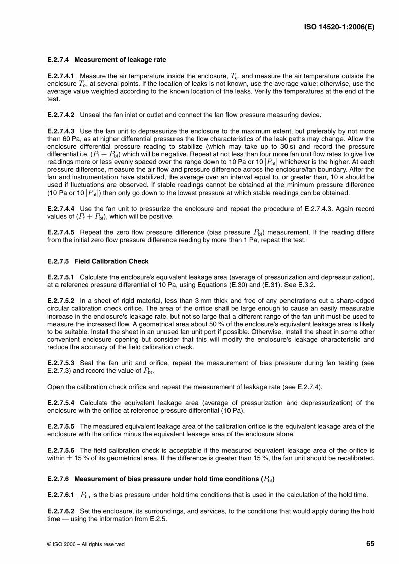
ISO 14520-1:2006(E)
© ISO 2006 – All rights reserved 65
E.2.7.4 Measurement of leakage rate
E.2.7.4.1 Measure the air temperature inside the enclosure, , and measure the air temperature outside theenclosure , at several points. If the location of leaks is not known, use the average value; otherwise, use theaverage value weighted according to the known location of the leaks. Verify the temperatures at the end of thetest.
E.2.7.4.2 Unseal the fan inlet or outlet and connect the fan flow pressure measuring device.
E.2.7.4.3 Use the fan unit to depressurize the enclosure to the maximum extent, but preferably by not morethan , as at higher differential pressures the flow characteristics of the leak paths may change. Allow theenclosure differential pressure reading to stabilize (which may take up to ) and record the pressuredifferential i.e. ( ) which will be negative. Repeat at not less than four more fan unit flow rates to give fivereadings more or less evenly spaced over the range down to or whichever is the higher. At eachpressure difference, measure the air flow and pressure difference across the enclosure/fan boundary. After thefan and instrumentation have stabilized, the average over an interval equal to, or greater than, should beused if fluctuations are observed. If stable readings cannot be obtained at the minimum pressure difference( or ) then only go down to the lowest pressure at which stable readings can be obtained.
E.2.7.4.4 Use the fan unit to pressurize the enclosure and repeat the procedure of E.2.7.4.3. Again recordvalues of ( ), which will be positive.
E.2.7.4.5 Repeat the zero flow pressure difference (bias pressure ) measurement. If the reading differsfrom the initial zero flow pressure difference reading by more than , repeat the test.
E.2.7.5 Field Calibration Check
E.2.7.5.1 Calculate the enclosure’s equivalent leakage area (average of pressurization and depressurization),at a reference pressure differential of , using Equations (E.30) and (E.31). See E.3.2.
E.2.7.5.2 In a sheet of rigid material, less than thick and free of any penetrations cut a sharp-edgedcircular calibration check orifice. The area of the orifice shall be large enough to cause an easily measurableincrease in the enclosure's leakage rate, but not so large that a different range of the fan unit must be used tomeasure the increased flow. A geometrical area about of the enclosure's equivalent leakage area is likelyto be suitable. Install the sheet in an unused fan unit port if possible. Otherwise, install the sheet in some otherconvenient enclosure opening but consider that this will modify the enclosure's leakage characteristic andreduce the accuracy of the field calibration check.
E.2.7.5.3 Seal the fan unit and orifice, repeat the measurement of bias pressure during fan testing (seeE.2.7.3) and record the value of .
Open the calibration check orifice and repeat the measurement of leakage rate (see E.2.7.4).
E.2.7.5.4 Calculate the equivalent leakage area (average of pressurization and depressurization) of theenclosure with the orifice at reference pressure differential ( ).
E.2.7.5.5 The measured equivalent leakage area of the calibration orifice is the equivalent leakage area of theenclosure with the orifice minus the equivalent leakage area of the enclosure alone.
E.2.7.5.6 The field calibration check is acceptable if the measured equivalent leakage area of the orifice iswithin of its geometrical area. If the difference is greater than , the fan unit should be recalibrated.
E.2.7.6 Measurement of bias pressure under hold time conditions ( )
E.2.7.6.1 is the bias pressure under hold time conditions that is used in the calculation of the hold time.
E.2.7.6.2 Set the enclosure, its surroundings, and services, to the conditions that would apply during the holdtime — using the information from E.2.5.
TeTo
60 Pa30 s
Pf + Pbt10 Pa 10 |Pbt|
10 s
10 Pa 10 |Pbt|
Pf + Pbt
Pbt1 Pa
10 Pa
3 mm
50 %
Pbt
10 Pa
± 15 % 15 %
Pbt
Pbh
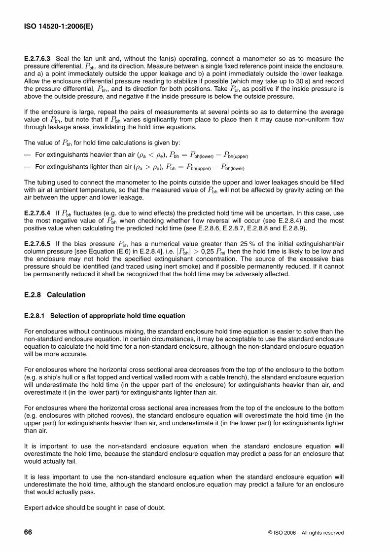
ISO 14520-1:2006(E)
66 © ISO 2006 – All rights reserved
E.2.7.6.3 Seal the fan unit and, without the fan(s) operating, connect a manometer so as to measure thepressure differential, , and its direction. Measure between a single fixed reference point inside the enclosure,and a) a point immediately outside the upper leakage and b) a point immediately outside the lower leakage.Allow the enclosure differential pressure reading to stabilize if possible (which may take up to ) and recordthe pressure differential, , and its direction for both positions. Take as positive if the inside pressure isabove the outside pressure, and negative if the inside pressure is below the outside pressure.
If the enclosure is large, repeat the pairs of measurements at several points so as to determine the averagevalue of , but note that if varies significantly from place to place then it may cause non-uniform flowthrough leakage areas, invalidating the hold time equations.
The value of for hold time calculations is given by:
— For extinguishants heavier than air ( ),
— For extinguishants lighter than air ( ),
The tubing used to connect the manometer to the points outside the upper and lower leakages should be filledwith air at ambient temperature, so that the measured value of will not be affected by gravity acting on theair between the upper and lower leakage.
E.2.7.6.4 If fluctuates (e.g. due to wind effects) the predicted hold time will be uncertain. In this case, usethe most negative value of when checking whether flow reversal will occur (see E.2.8.4) and the mostpositive value when calculating the predicted hold time (see E.2.8.6, E.2.8.7, E.2.8.8 and E.2.8.9).
E.2.7.6.5 If the bias pressure has a numerical value greater than of the initial extinguishant/aircolumn pressure [see Equation (E.6) in E.2.8.4], i.e. then the hold time is likely to be low andthe enclosure may not hold the specified extinguishant concentration. The source of the excessive biaspressure should be identified (and traced using inert smoke) and if possible permanently reduced. If it cannotbe permanently reduced it shall be recognized that the hold time may be adversely affected.
E.2.8 Calculation
E.2.8.1 Selection of appropriate hold time equation
For enclosures without continuous mixing, the standard enclosure hold time equation is easier to solve than thenon-standard enclosure equation. In certain circumstances, it may be acceptable to use the standard enclosureequation to calculate the hold time for a non-standard enclosure, although the non-standard enclosure equationwill be more accurate.
For enclosures where the horizontal cross sectional area decreases from the top of the enclosure to the bottom(e.g. a ship's hull or a flat topped and vertical walled room with a cable trench), the standard enclosure equationwill underestimate the hold time (in the upper part of the enclosure) for extinguishants heavier than air, andoverestimate it (in the lower part) for extinguishants lighter than air.
For enclosures where the horizontal cross sectional area increases from the top of the enclosure to the bottom(e.g. enclosures with pitched rooves), the standard enclosure equation will overestimate the hold time (in theupper part) for extinguishants heavier than air, and underestimate it (in the lower part) for extinguishants lighterthan air.
It is important to use the non-standard enclosure equation when the standard enclosure equation willoverestimate the hold time, because the standard enclosure equation may predict a pass for an enclosure thatwould actually fail.
It is less important to use the non-standard enclosure equation when the standard enclosure equation willunderestimate the hold time, although the standard enclosure equation may predict a failure for an enclosurethat would actually pass.
Expert advice should be sought in case of doubt.
Pbh
30 sPbh Pbh
Pbh Pbh
Pbh
ρa < ρe Pbh = Pbh(lower) − Pbh(upper)
ρa > ρe Pbh = Pbh(upper) − Pbh(lower)
Pbh
PbhPbh
Pbh 25 %|Pbh| > 0,25 Pmi
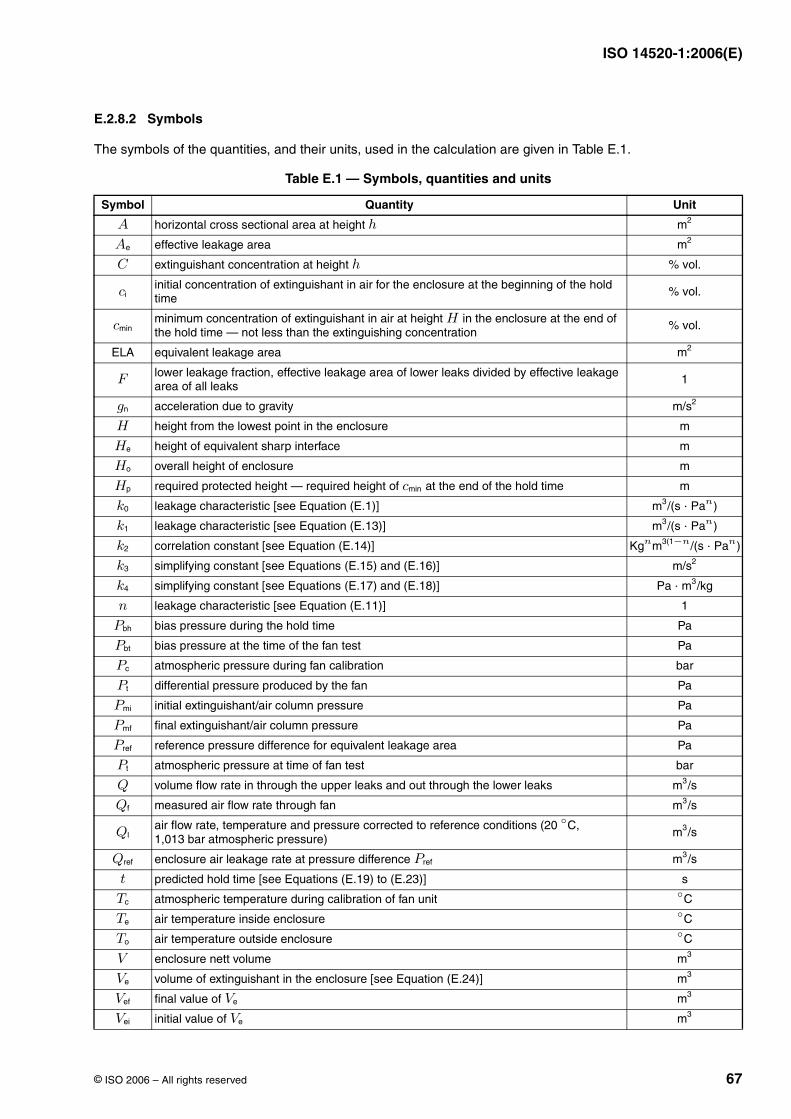
ISO 14520-1:2006(E)
© ISO 2006 – All rights reserved 67
E.2.8.2 Symbols
The symbols of the quantities, and their units, used in the calculation are given in Table E.1.
Table E.1 — Symbols, quantities and units
Symbol Quantity Unit
horizontal cross sectional area at height
effective leakage area
extinguishant concentration at height
initial concentration of extinguishant in air for the enclosure at the beginning of the hold time
minimum concentration of extinguishant in air at height in the enclosure at the end of the hold time — not less than the extinguishing concentration
ELA equivalent leakage area
lower leakage fraction, effective leakage area of lower leaks divided by effective leakage area of all leaks
1
acceleration due to gravity
height from the lowest point in the enclosure m
height of equivalent sharp interface m
overall height of enclosure m
required protected height — required height of at the end of the hold time m
leakage characteristic [see Equation (E.1)]
leakage characteristic [see Equation (E.13)]
correlation constant [see Equation (E.14)]
simplifying constant [see Equations (E.15) and (E.16)]
simplifying constant [see Equations (E.17) and (E.18)]
leakage characteristic [see Equation (E.11)] 1
bias pressure during the hold time Pa
bias pressure at the time of the fan test Pa
atmospheric pressure during fan calibration bar
differential pressure produced by the fan Pa
initial extinguishant/air column pressure Pa
final extinguishant/air column pressure Pa
reference pressure difference for equivalent leakage area Pa
atmospheric pressure at time of fan test bar
volume flow rate in through the upper leaks and out through the lower leaks
measured air flow rate through fan
air flow rate, temperature and pressure corrected to reference conditions ( , 1,013 bar atmospheric pressure)
enclosure air leakage rate at pressure difference
predicted hold time [see Equations (E.19) to (E.23)] s
atmospheric temperature during calibration of fan unit
air temperature inside enclosure
air temperature outside enclosure
enclosure nett volume
volume of extinguishant in the enclosure [see Equation (E.24)]
final value of
initial value of
A h m2
Ae m2
C h % vol.
ci % vol.
cminH % vol.
m2
F
gn m/s2
H
He
Ho
Hp cmin
k0 m3/(s · Pan)
k1 m3/(s · Pan)
k2 Kgnm3(1−n/(s · Pan)
k3 m/s2
k4 Pa · m3/kg
n
Pbh
Pbt
Pc
Pt
Pmi
Pmf
Pref
Pt
Q m3/s
Qf m3/s
Ql20 ◦C
m3/s
Qref Pref m3/s
t
Tc◦C
Te◦C
To◦C
V m3
Ve m3
Vef Ve m3
Vei Ve m3
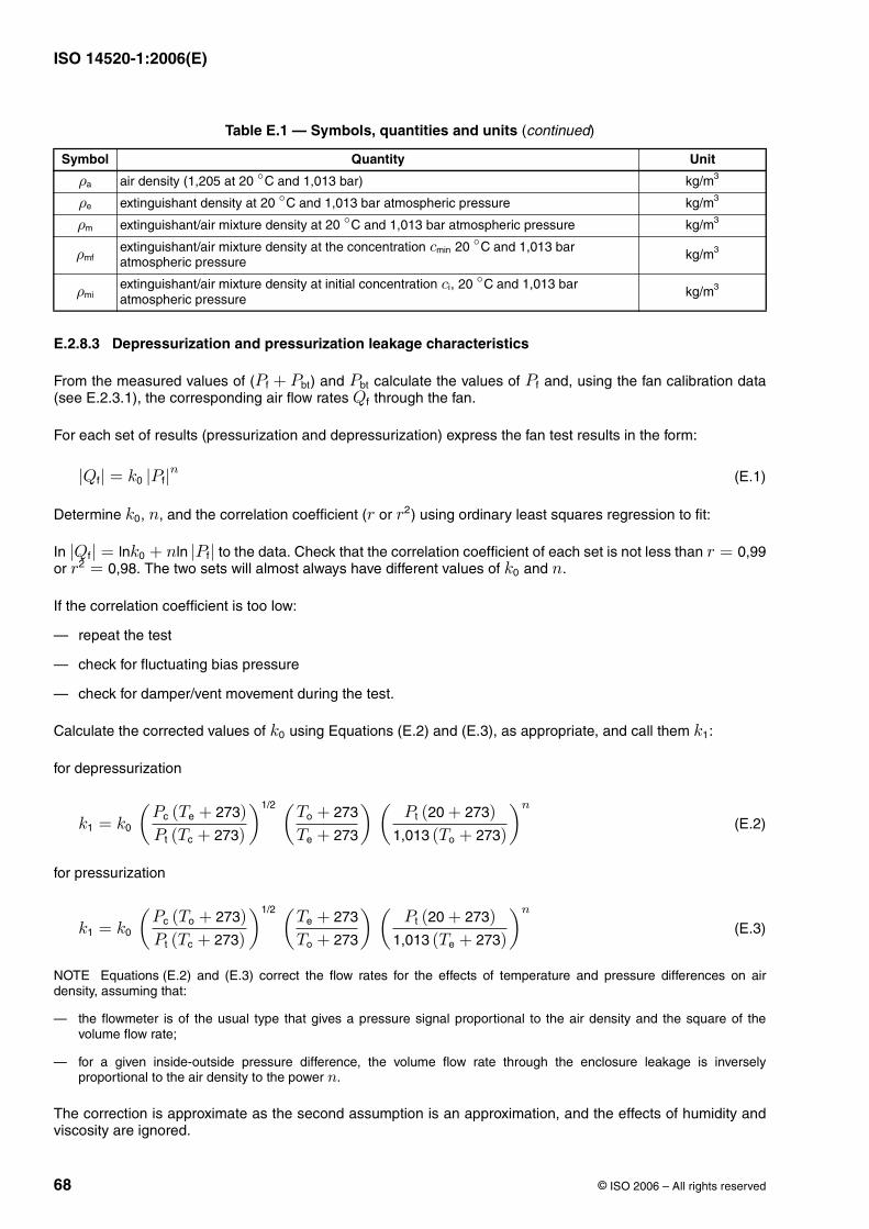
ISO 14520-1:2006(E)
68 © ISO 2006 – All rights reserved
E.2.8.3 Depressurization and pressurization leakage characteristics
From the measured values of ( ) and calculate the values of and, using the fan calibration data(see E.2.3.1), the corresponding air flow rates through the fan.
For each set of results (pressurization and depressurization) express the fan test results in the form:
(E.1)
Determine , , and the correlation coefficient ( or ) using ordinary least squares regression to fit:
In to the data. Check that the correlation coefficient of each set is not less than or . The two sets will almost always have different values of and .
If the correlation coefficient is too low:
— repeat the test
— check for fluctuating bias pressure
— check for damper/vent movement during the test.
Calculate the corrected values of using Equations (E.2) and (E.3), as appropriate, and call them :
for depressurization
(E.2)
for pressurization
(E.3)
NOTE Equations (E.2) and (E.3) correct the flow rates for the effects of temperature and pressure differences on airdensity, assuming that:
— the flowmeter is of the usual type that gives a pressure signal proportional to the air density and the square of thevolume flow rate;
— for a given inside-outside pressure difference, the volume flow rate through the enclosure leakage is inverselyproportional to the air density to the power .
The correction is approximate as the second assumption is an approximation, and the effects of humidity andviscosity are ignored.
air density (1,205 at and 1,013 bar)
extinguishant density at and 1,013 bar atmospheric pressure
extinguishant/air mixture density at and 1,013 bar atmospheric pressure
extinguishant/air mixture density at the concentration and 1,013 bar atmospheric pressure
extinguishant/air mixture density at initial concentration , and 1,013 bar atmospheric pressure
Table E.1 — Symbols, quantities and units (continued)
Symbol Quantity Unit
ρa 20 ◦C kg/m3
ρe 20 ◦C kg/m3
ρm 20 ◦C kg/m3
ρmfcmin 20 ◦C
kg/m3
ρmici 20 ◦C kg/m3
Pf + Pbt Pbt PfQf
|Qf| = k0 |Pf|n
k0 n r r2
|Qf| = lnk0 + nln |Pf| r = 0,99r2 = 0,98 k0 n
k0 k1
k1 = k0
(Pc (Te + 273)Pt (Tc + 273)
)1/2 (To + 273
Te + 273
) (Pt (20 + 273)
1,013 (To + 273)
)n
k1 = k0
(Pc (To + 273)Pt (Tc + 273)
)1/2 (Te + 273
To + 273
) (Pt (20 + 273)
1,013 (Te + 273)
)n
n
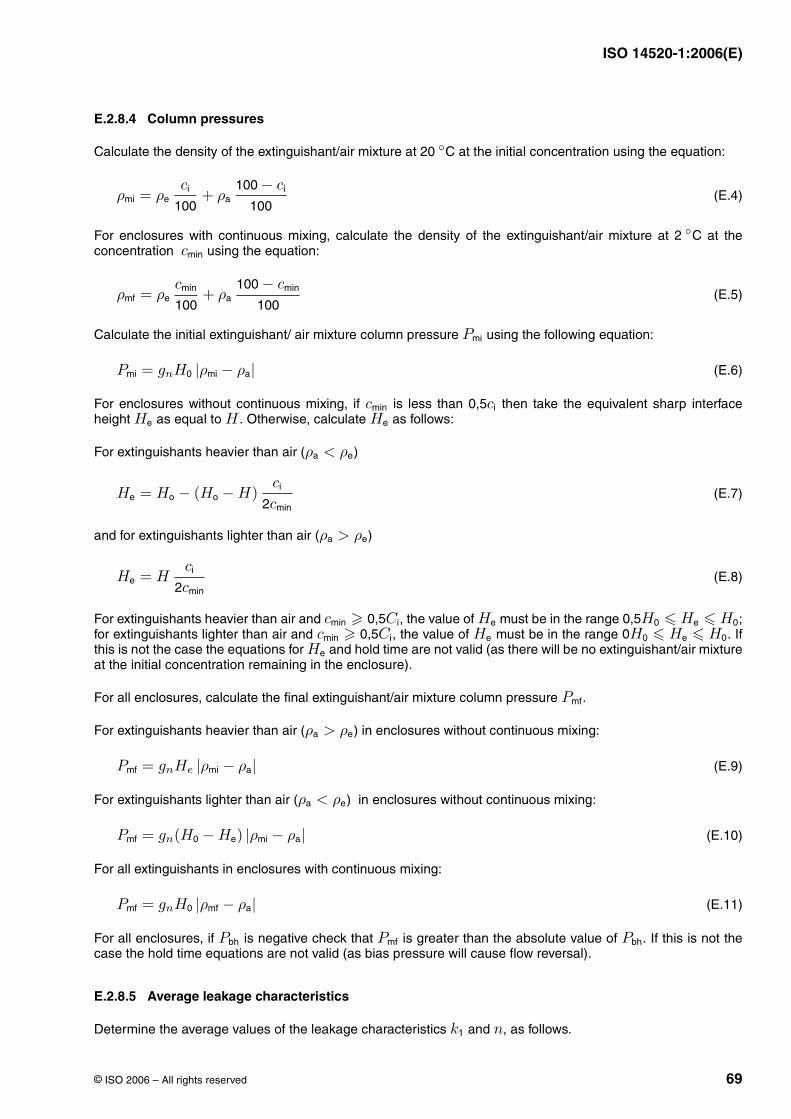
ISO 14520-1:2006(E)
© ISO 2006 – All rights reserved 69
E.2.8.4 Column pressures
Calculate the density of the extinguishant/air mixture at at the initial concentration using the equation:
(E.4)
For enclosures with continuous mixing, calculate the density of the extinguishant/air mixture at at theconcentration using the equation:
(E.5)
Calculate the initial extinguishant/ air mixture column pressure using the following equation:
(E.6)
For enclosures without continuous mixing, if is less than then take the equivalent sharp interfaceheight as equal to . Otherwise, calculate as follows:
For extinguishants heavier than air ( )
(E.7)
and for extinguishants lighter than air ( )
(E.8)
For extinguishants heavier than air and , the value of must be in the range ;for extinguishants lighter than air and , the value of must be in the range . Ifthis is not the case the equations for and hold time are not valid (as there will be no extinguishant/air mixtureat the initial concentration remaining in the enclosure).
For all enclosures, calculate the final extinguishant/air mixture column pressure .
For extinguishants heavier than air ( ) in enclosures without continuous mixing:
(E.9)
For extinguishants lighter than air ( ) in enclosures without continuous mixing:
(E.10)
For all extinguishants in enclosures with continuous mixing:
(E.11)
For all enclosures, if is negative check that is greater than the absolute value of . If this is not thecase the hold time equations are not valid (as bias pressure will cause flow reversal).
E.2.8.5 Average leakage characteristics
Determine the average values of the leakage characteristics and , as follows.
20 ◦C
ρmi = ρeci
100+ ρa
100 − ci
100
2 ◦Ccmin
ρmf = ρecmin
100+ ρa
100 − cmin
100
Pmi
Pmi = gnH0 |ρmi − ρa|
cmin 0,5ciHe H He
ρa < ρe
He = Ho − (Ho − H)ci
2cmin
ρa > ρe
He = Hci
2cmin
cmin � 0,5Ci He 0,5H0 � He � H0cmin � 0,5Ci He 0H0 � He � H0
He
Pmf
ρa > ρe
Pmf = gnHe |ρmi − ρa|
ρa < ρe
Pmf = gn(H0 − He) |ρmi − ρa|
Pmf = gnH0 |ρmf − ρa|
Pbh Pmf Pbh
k1 n
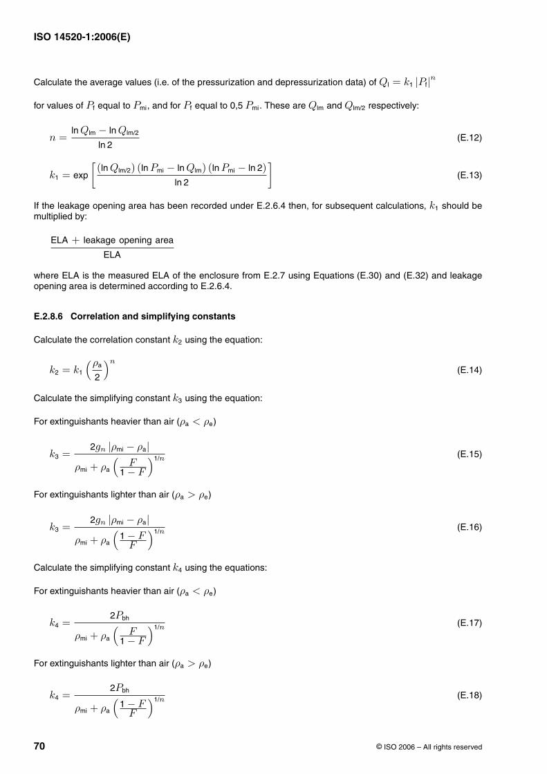
ISO 14520-1:2006(E)
70 © ISO 2006 – All rights reserved
Calculate the average values (i.e. of the pressurization and depressurization data) of
for values of equal to , and for equal to . These are and respectively:
(E.12)
(E.13)
If the leakage opening area has been recorded under E.2.6.4 then, for subsequent calculations, should bemultiplied by:
where ELA is the measured ELA of the enclosure from E.2.7 using Equations (E.30) and (E.32) and leakageopening area is determined according to E.2.6.4.
E.2.8.6 Correlation and simplifying constants
Calculate the correlation constant using the equation:
(E.14)
Calculate the simplifying constant using the equation:
For extinguishants heavier than air ( )
(E.15)
For extinguishants lighter than air ( )
(E.16)
Calculate the simplifying constant using the equations:
For extinguishants heavier than air ( )
(E.17)
For extinguishants lighter than air ( )
(E.18)
Ql = k1 |Pf|n
Pf Pmi Pf 0,5 Pmi Qlm Qlm/2
n =ln Qlm − ln Qlm/2
ln 2
k1 = exp
[(ln Qlm/2) (ln Pmi − ln Qlm) (ln Pmi − ln 2)
ln 2
]
k1
ELA + leakage opening area
ELA
k2
k2 = k1
(ρa
2
)n
k3
ρa < ρe
k3 =2gn |ρmi − ρa|
ρmi + ρa
(F
1 − F
)1/n
ρa > ρe
k3 =2gn |ρmi − ρa|
ρmi + ρa
(1 − F
F
)1/n
k4
ρa < ρe
k4 =2Pbh
ρmi + ρa
(F
1 − F
)1/n
ρa > ρe
k4 =2Pbh
ρmi + ρa
(1 − F
F
)1/n
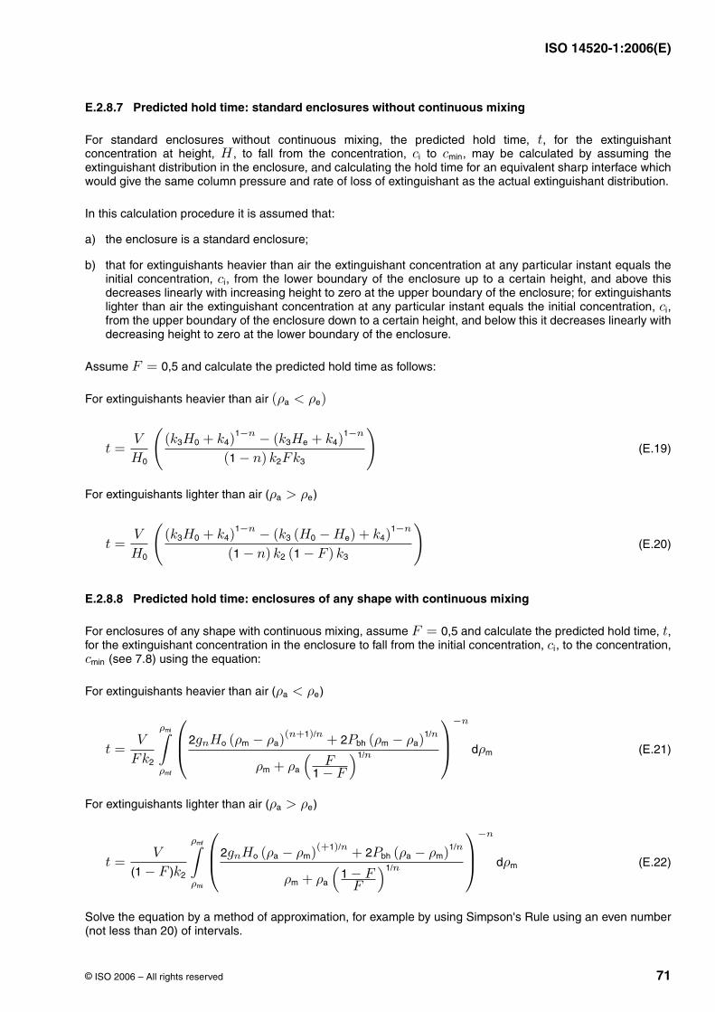
ISO 14520-1:2006(E)
© ISO 2006 – All rights reserved 71
E.2.8.7 Predicted hold time: standard enclosures without continuous mixing
For standard enclosures without continuous mixing, the predicted hold time, , for the extinguishantconcentration at height, , to fall from the concentration, to , may be calculated by assuming theextinguishant distribution in the enclosure, and calculating the hold time for an equivalent sharp interface whichwould give the same column pressure and rate of loss of extinguishant as the actual extinguishant distribution.
In this calculation procedure it is assumed that:
a) the enclosure is a standard enclosure;
b) that for extinguishants heavier than air the extinguishant concentration at any particular instant equals theinitial concentration, , from the lower boundary of the enclosure up to a certain height, and above thisdecreases linearly with increasing height to zero at the upper boundary of the enclosure; for extinguishantslighter than air the extinguishant concentration at any particular instant equals the initial concentration, ,from the upper boundary of the enclosure down to a certain height, and below this it decreases linearly withdecreasing height to zero at the lower boundary of the enclosure.
Assume and calculate the predicted hold time as follows:
For extinguishants heavier than air
(E.19)
For extinguishants lighter than air ( )
(E.20)
E.2.8.8 Predicted hold time: enclosures of any shape with continuous mixing
For enclosures of any shape with continuous mixing, assume and calculate the predicted hold time, ,for the extinguishant concentration in the enclosure to fall from the initial concentration, , to the concentration,
(see 7.8) using the equation:
For extinguishants heavier than air ( )
(E.21)
For extinguishants lighter than air ( )
(E.22)
Solve the equation by a method of approximation, for example by using Simpson's Rule using an even number(not less than 20) of intervals.
tH ci cmin
ci
ci
F = 0,5
(ρa < ρe)
t =V
H0
((k3H0 + k4)
1−n − (k3He + k4)1−n
(1 − n) k2Fk3
)
ρa > ρe
t =V
H0
((k3H0 + k4)
1−n − (k3 (H0 − He) + k4)1−n
(1 − n) k2 (1 − F ) k3
)
F = 0,5 tci
cmin
ρa < ρe
t =V
Fk2
ρmi∫ρmf
⎛⎜⎝2gnHo (ρm − ρa)
(n+1)/n + 2Pbh (ρm − ρa)1/n
ρm + ρa
(F
1 − F
)1/n
⎞⎟⎠
−n
dρm
ρa > ρe
t =V
(1 − F )k2
ρmf∫ρmi
⎛⎜⎝2gnHo (ρa − ρm)(+1)/n + 2Pbh (ρa − ρm)1/n
ρm + ρa
(1 − F
F
)1/n
⎞⎟⎠
−n
dρm
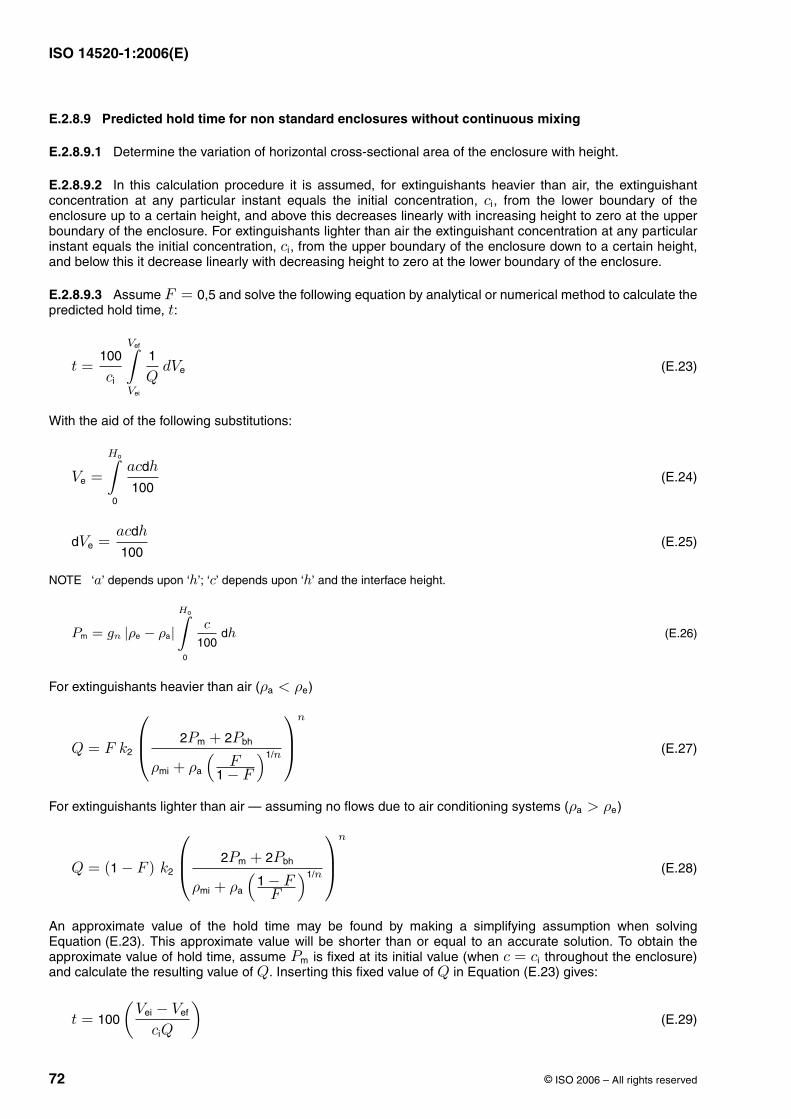
ISO 14520-1:2006(E)
72 © ISO 2006 – All rights reserved
E.2.8.9 Predicted hold time for non standard enclosures without continuous mixing
E.2.8.9.1 Determine the variation of horizontal cross-sectional area of the enclosure with height.
E.2.8.9.2 In this calculation procedure it is assumed, for extinguishants heavier than air, the extinguishantconcentration at any particular instant equals the initial concentration, , from the lower boundary of theenclosure up to a certain height, and above this decreases linearly with increasing height to zero at the upperboundary of the enclosure. For extinguishants lighter than air the extinguishant concentration at any particularinstant equals the initial concentration, , from the upper boundary of the enclosure down to a certain height,and below this it decrease linearly with decreasing height to zero at the lower boundary of the enclosure.
E.2.8.9.3 Assume and solve the following equation by analytical or numerical method to calculate thepredicted hold time, :
(E.23)
With the aid of the following substitutions:
(E.24)
(E.25)
NOTE ‘ ’ depends upon ‘ ’; ‘ ’ depends upon ‘ ’ and the interface height.
(E.26)
For extinguishants heavier than air ( )
(E.27)
For extinguishants lighter than air — assuming no flows due to air conditioning systems ( )
(E.28)
An approximate value of the hold time may be found by making a simplifying assumption when solvingEquation (E.23). This approximate value will be shorter than or equal to an accurate solution. To obtain theapproximate value of hold time, assume is fixed at its initial value (when throughout the enclosure)and calculate the resulting value of . Inserting this fixed value of in Equation (E.23) gives:
(E.29)
ci
ci
F = 0,5t
t =100
ci
Vef∫Vei
1
QdVe
Ve =
Ho∫0
acdh
100
dVe =acdh
100
a h c h
Pm = gn |ρe − ρa|Ho∫
0
c
100dh
ρa < ρe
Q = F k2
⎛⎜⎝ 2Pm + 2Pbh
ρmi + ρa
(F
1 − F
)1/n
⎞⎟⎠
n
ρa > ρe
Q = (1 − F ) k2
⎛⎜⎝ 2Pm + 2Pbh
ρmi + ρa
(1 − F
F
)1/n
⎞⎟⎠
n
Pm c = ciQ Q
t = 100
(Vei − Vef
ciQ
)
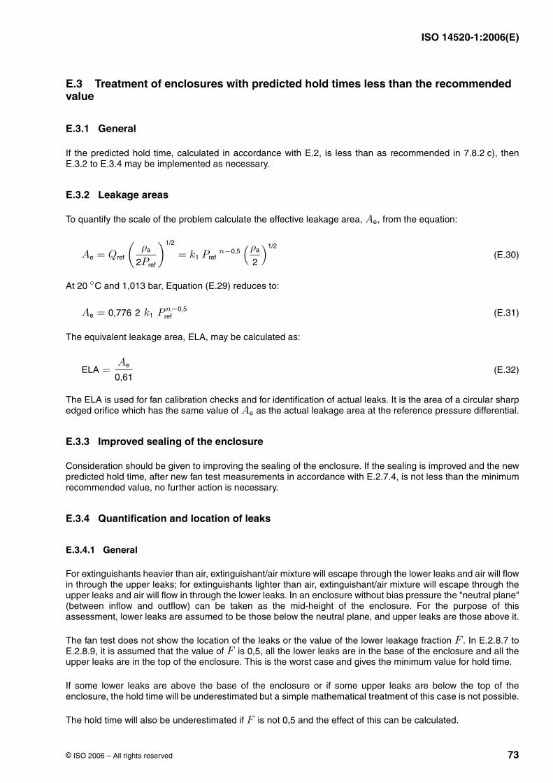
ISO 14520-1:2006(E)
© ISO 2006 – All rights reserved 73
E.3 Treatment of enclosures with predicted hold times less than the recommended value
E.3.1 General
If the predicted hold time, calculated in accordance with E.2, is less than as recommended in 7.8.2 c), thenE.3.2 to E.3.4 may be implemented as necessary.
E.3.2 Leakage areas
To quantify the scale of the problem calculate the effective leakage area, , from the equation:
(E.30)
At and 1,013 bar, Equation (E.29) reduces to:
(E.31)
The equivalent leakage area, ELA, may be calculated as:
(E.32)
The ELA is used for fan calibration checks and for identification of actual leaks. It is the area of a circular sharpedged orifice which has the same value of as the actual leakage area at the reference pressure differential.
E.3.3 Improved sealing of the enclosure
Consideration should be given to improving the sealing of the enclosure. If the sealing is improved and the newpredicted hold time, after new fan test measurements in accordance with E.2.7.4, is not less than the minimumrecommended value, no further action is necessary.
E.3.4 Quantification and location of leaks
E.3.4.1 General
For extinguishants heavier than air, extinguishant/air mixture will escape through the lower leaks and air will flowin through the upper leaks; for extinguishants lighter than air, extinguishant/air mixture will escape through theupper leaks and air will flow in through the lower leaks. In an enclosure without bias pressure the "neutral plane"(between inflow and outflow) can be taken as the mid-height of the enclosure. For the purpose of thisassessment, lower leaks are assumed to be those below the neutral plane, and upper leaks are those above it.
The fan test does not show the location of the leaks or the value of the lower leakage fraction . In E.2.8.7 toE.2.8.9, it is assumed that the value of is 0,5, all the lower leaks are in the base of the enclosure and all theupper leaks are in the top of the enclosure. This is the worst case and gives the minimum value for hold time.
If some lower leaks are above the base of the enclosure or if some upper leaks are below the top of theenclosure, the hold time will be underestimated but a simple mathematical treatment of this case is not possible.
The hold time will also be underestimated if is not 0,5 and the effect of this can be calculated.
Ae
Ae = Qref
(ρa
2Pref
)1/2
= k1 Prefn−0,5
(ρa
2
)1/2
20 ◦C
Ae = 0,776 2 k1 Pn−0,5ref
ELA =Ae
0,61
Ae
FF
F
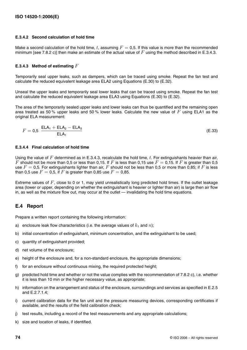
ISO 14520-1:2006(E)
74 © ISO 2006 – All rights reserved
E.3.4.2 Second calculation of hold time
Make a second calculation of the hold time, , assuming . If this value is more than the recommendedminimum [see 7.8.2 c)] then make an estimate of the actual value of using the method described in E.3.4.3.
E.3.4.3 Method of estimating
Temporarily seal upper leaks, such as dampers, which can be traced using smoke. Repeat the fan test andcalculate the reduced equivalent leakage area ELA2 using Equations (E.30) to (E.32).
Unseal the upper leaks and temporarily seal lower leaks that can be traced using smoke. Repeat the fan testand calculate the reduced equivalent leakage area ELA3 using Equations (E.30) to (E.32).
The area of the temporarily sealed upper leaks and lower leaks can thus be quantified and the remaining openarea treated as upper leaks and lower leaks. Calculate the new value of using ELA1 as theoriginal ELA measurement:
(E.33)
E.3.4.4 Final calculation of hold time
Using the value of determined as in E.3.4.3, recalculate the hold time, . For extinguishants heavier than air, should not be more than 0,5 or less than 0,15. If is less than 0,15 use . If is greater than 0,5
use . For extinguishants lighter than air, should not be less than 0,5 or more than 0,85; if is lessthan 0,5 use , if is greater than 0,85 use .
Extreme values of , close to 0 or 1, may yield unrealistically long predicted hold times. If the outlet leakagearea (lower or upper, depending on whether the extinguishant is heavier or lighter than air) is large then air flowin, as well as the mixture flow out, may occur at the outlet — invalidating the hold time equations.
E.4 Report
Prepare a written report containing the following information:
a) enclosure leak flow characteristics (i.e. the average values of and );
b) initial concentration of extinguishant, minimum concentration, and the extinguishant to be used;
c) quantity of extinguishant provided;
d) net volume of the enclosure;
e) height of the enclosure and, for a non-standard enclosure, the appropriate dimensions;
f) for an enclosure without continuous mixing, the required protected height;
g) predicted hold time and whether or not the value complies with the recommendation of 7.8.2 c), i.e. whetherit is less than or the higher necessary value, as appropriate;
h) information on the arrangement and status of the enclosure, surroundings and services as specified in E.2.5and E.2.7.1.4;
i) current calibration data for the fan unit and the pressure measuring devices, corresponding certificates ifavailable, and the results of the field calibration check;
j) test results, including a record of the test measurements and any appropriate calculations;
k) size and location of leaks, if identified.
t F = 0,5F
F
50 % 50 % F
F = 0,5ELA1 + ELA2 − ELA3
ELA1
F tF F F = 0,15 F
F = 0,5 F FF = 0,5 F F = 0,85
F
k1 n
10 min
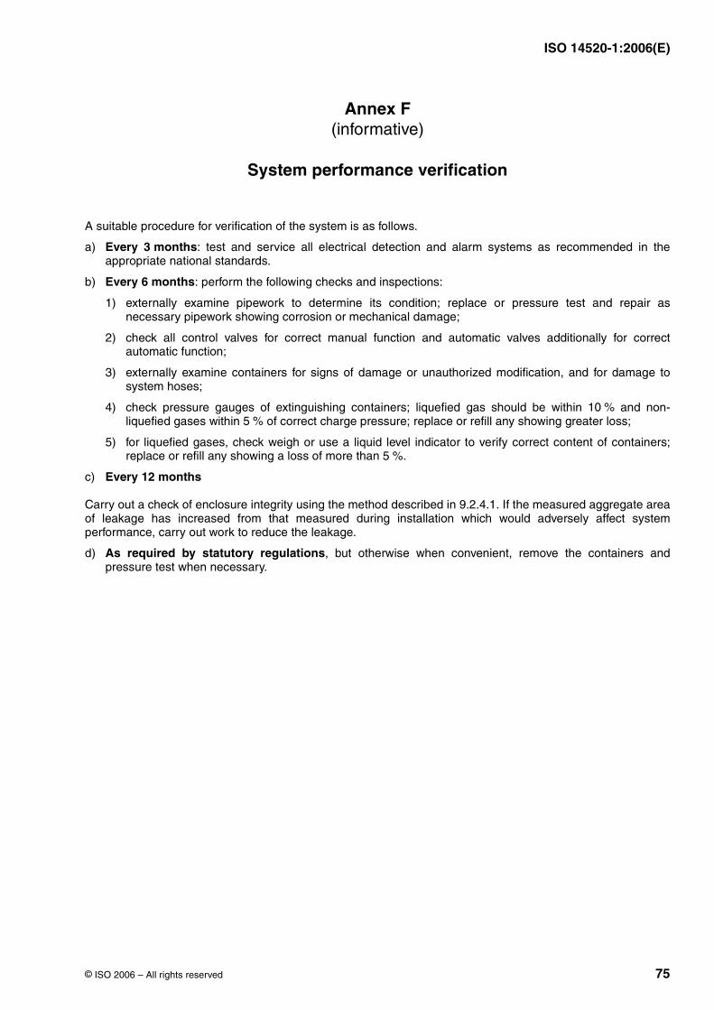
ISO 14520-1:2006(E)
© ISO 2006 – All rights reserved 75
Annex F(informative)
System performance verification
A suitable procedure for verification of the system is as follows.
a) Every 3 months: test and service all electrical detection and alarm systems as recommended in theappropriate national standards.
b) Every 6 months: perform the following checks and inspections:
1) externally examine pipework to determine its condition; replace or pressure test and repair asnecessary pipework showing corrosion or mechanical damage;
2) check all control valves for correct manual function and automatic valves additionally for correctautomatic function;
3) externally examine containers for signs of damage or unauthorized modification, and for damage tosystem hoses;
4) check pressure gauges of extinguishing containers; liquefied gas should be within and non-liquefied gases within of correct charge pressure; replace or refill any showing greater loss;
5) for liquefied gases, check weigh or use a liquid level indicator to verify correct content of containers;replace or refill any showing a loss of more than .
c) Every 12 months
Carry out a check of enclosure integrity using the method described in 9.2.4.1. If the measured aggregate areaof leakage has increased from that measured during installation which would adversely affect systemperformance, carry out work to reduce the leakage.
d) As required by statutory regulations, but otherwise when convenient, remove the containers andpressure test when necessary.
10 %5 %
5 %
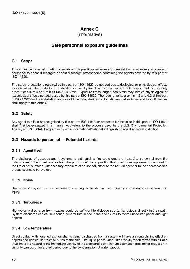
ISO 14520-1:2006(E)
76 © ISO 2006 – All rights reserved
Annex G(informative)
Safe personnel exposure guidelines
G.1 Scope
This annex contains information to establish the practices necessary to prevent the unnecessary exposure ofpersonnel to agent discharges or post discharge atmospheres containing the agents covered by this part ofISO 14520.
The safety precautions required by this part of ISO 14520 do not address toxicological or physiological effectsassociated with the products of combustion caused by fire. The maximum exposure time assumed by the safetyprecautions in this part of ISO 14520 is . Exposure times longer than may involve physiological ortoxicological effects not addressed by this part of ISO 14520. The requirements given in 4.2 and 4.3 of this partof ISO 14520 for the installation and use of time delay devices, automatic/manual switches and lock off devicesshall apply to this Annex.
G.2 Safety
Any agent that is to be recognized by this part of ISO 14520 or proposed for inclusion in this part of ISO 14520shall first be evaluated in a manner equivalent to the process used by the U.S. Environmental ProtectionAgency's (EPA) SNAP Program or by other international/national extinguishing agent approval institution.
G.3 Hazards to personnel — Potential hazards
G.3.1 Agent itself
The discharge of gaseous agent systems to extinguish a fire could create a hazard to personnel from thenatural form of the agent itself or from the products of decomposition that result from exposure of the agent tothe fire or hot surfaces. Unnecessary exposure of personnel, either to the natural agent or to the decompositionproducts, should be avoided.
G.3.2 Noise
Discharge of a system can cause noise loud enough to be startling but ordinarily insufficient to cause traumaticinjury.
G.3.3 Turbulence
High-velocity discharge from nozzles could be sufficient to dislodge substantial objects directly in their path.System discharge can cause enough general turbulence in the enclosures to move unsecured paper and lightobjects.
G.3.4 Low temperature
Direct contact with liquefied extinguishants being discharged from a system will have a strong chilling effect onobjects and can cause frostbite burns to the skin. The liquid phase vapourizes rapidly when mixed with air andthus limits the hazard to the immediate vicinity of the discharge point. In humid atmospheres, minor reduction invisibility can occur for a brief period due to the condensation of water vapour.
5 min 5 min
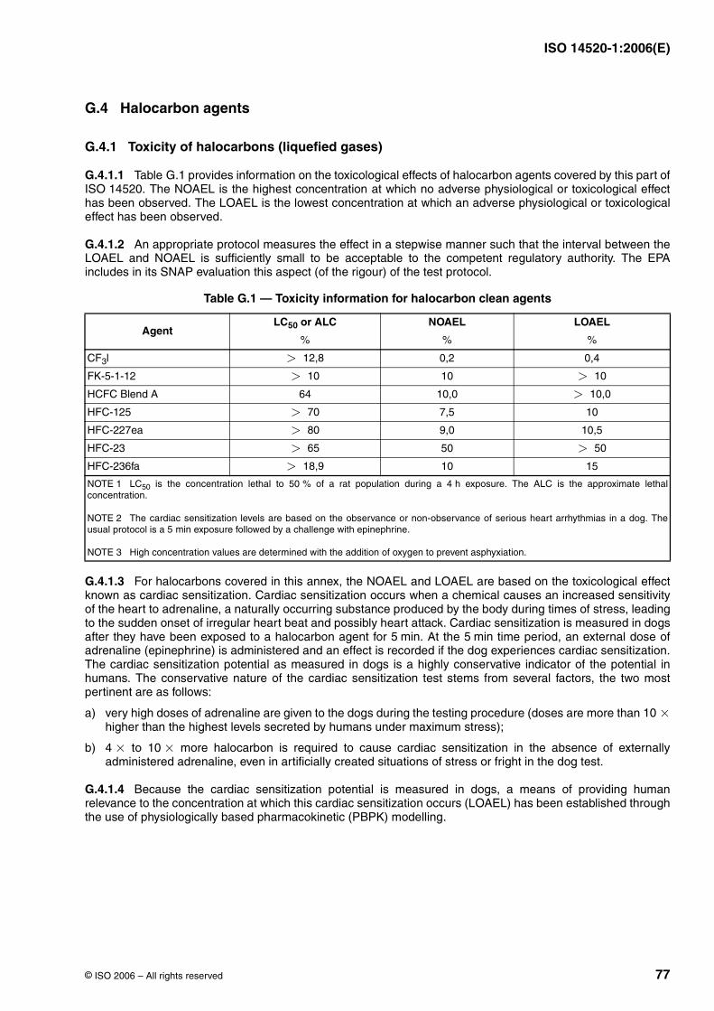
ISO 14520-1:2006(E)
© ISO 2006 – All rights reserved 77
G.4 Halocarbon agents
G.4.1 Toxicity of halocarbons (liquefied gases)
G.4.1.1 Table G.1 provides information on the toxicological effects of halocarbon agents covered by this part ofISO 14520. The NOAEL is the highest concentration at which no adverse physiological or toxicological effecthas been observed. The LOAEL is the lowest concentration at which an adverse physiological or toxicologicaleffect has been observed.
G.4.1.2 An appropriate protocol measures the effect in a stepwise manner such that the interval between theLOAEL and NOAEL is sufficiently small to be acceptable to the competent regulatory authority. The EPAincludes in its SNAP evaluation this aspect (of the rigour) of the test protocol.
G.4.1.3 For halocarbons covered in this annex, the NOAEL and LOAEL are based on the toxicological effectknown as cardiac sensitization. Cardiac sensitization occurs when a chemical causes an increased sensitivityof the heart to adrenaline, a naturally occurring substance produced by the body during times of stress, leadingto the sudden onset of irregular heart beat and possibly heart attack. Cardiac sensitization is measured in dogsafter they have been exposed to a halocarbon agent for . At the time period, an external dose ofadrenaline (epinephrine) is administered and an effect is recorded if the dog experiences cardiac sensitization.The cardiac sensitization potential as measured in dogs is a highly conservative indicator of the potential inhumans. The conservative nature of the cardiac sensitization test stems from several factors, the two mostpertinent are as follows:
a) very high doses of adrenaline are given to the dogs during the testing procedure (doses are more than higher than the highest levels secreted by humans under maximum stress);
b) to more halocarbon is required to cause cardiac sensitization in the absence of externallyadministered adrenaline, even in artificially created situations of stress or fright in the dog test.
G.4.1.4 Because the cardiac sensitization potential is measured in dogs, a means of providing humanrelevance to the concentration at which this cardiac sensitization occurs (LOAEL) has been established throughthe use of physiologically based pharmacokinetic (PBPK) modelling.
Table G.1 — Toxicity information for halocarbon clean agents
AgentLC50 or ALC NOAEL LOAEL
CF3l 0,2 0,4
FK-5-1-12 10
HCFC Blend A 64 10,0
HFC-125 7,5 10
HFC-227ea 9,0 10,5
HFC-23 50
HFC-236fa 10 15
NOTE 1 LC50 is the concentration lethal to of a rat population during a exposure. The ALC is the approximate lethalconcentration.
NOTE 2 The cardiac sensitization levels are based on the observance or non-observance of serious heart arrhythmias in a dog. Theusual protocol is a exposure followed by a challenge with epinephrine.
NOTE 3 High concentration values are determined with the addition of oxygen to prevent asphyxiation.
% % %
> 12,8
> 10 > 10
> 10,0
> 70
> 80
> 65 > 50
> 18,9
50 % 4 h
5 min
5 min 5 min
10 ×
4 × 10 ×
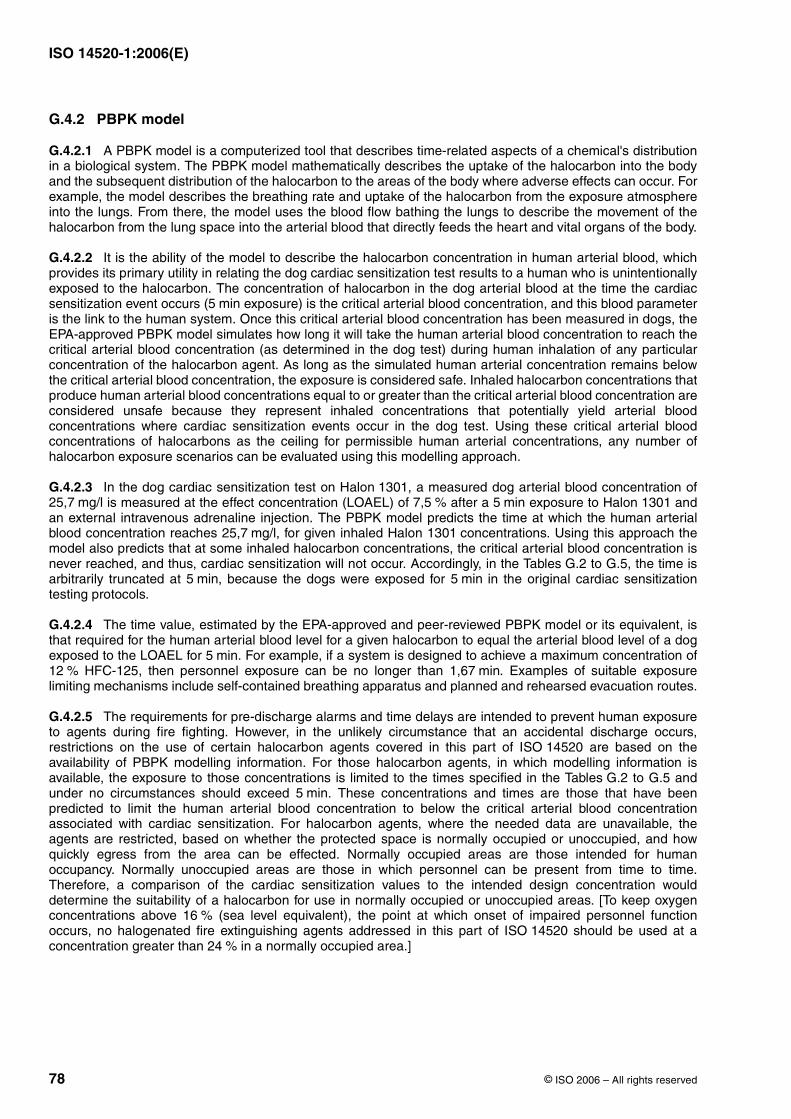
ISO 14520-1:2006(E)
78 © ISO 2006 – All rights reserved
G.4.2 PBPK model
G.4.2.1 A PBPK model is a computerized tool that describes time-related aspects of a chemical's distributionin a biological system. The PBPK model mathematically describes the uptake of the halocarbon into the bodyand the subsequent distribution of the halocarbon to the areas of the body where adverse effects can occur. Forexample, the model describes the breathing rate and uptake of the halocarbon from the exposure atmosphereinto the lungs. From there, the model uses the blood flow bathing the lungs to describe the movement of thehalocarbon from the lung space into the arterial blood that directly feeds the heart and vital organs of the body.
G.4.2.2 It is the ability of the model to describe the halocarbon concentration in human arterial blood, whichprovides its primary utility in relating the dog cardiac sensitization test results to a human who is unintentionallyexposed to the halocarbon. The concentration of halocarbon in the dog arterial blood at the time the cardiacsensitization event occurs ( exposure) is the critical arterial blood concentration, and this blood parameteris the link to the human system. Once this critical arterial blood concentration has been measured in dogs, theEPA-approved PBPK model simulates how long it will take the human arterial blood concentration to reach thecritical arterial blood concentration (as determined in the dog test) during human inhalation of any particularconcentration of the halocarbon agent. As long as the simulated human arterial concentration remains belowthe critical arterial blood concentration, the exposure is considered safe. Inhaled halocarbon concentrations thatproduce human arterial blood concentrations equal to or greater than the critical arterial blood concentration areconsidered unsafe because they represent inhaled concentrations that potentially yield arterial bloodconcentrations where cardiac sensitization events occur in the dog test. Using these critical arterial bloodconcentrations of halocarbons as the ceiling for permissible human arterial concentrations, any number ofhalocarbon exposure scenarios can be evaluated using this modelling approach.
G.4.2.3 In the dog cardiac sensitization test on Halon 1301, a measured dog arterial blood concentration of is measured at the effect concentration (LOAEL) of after a exposure to Halon 1301 and
an external intravenous adrenaline injection. The PBPK model predicts the time at which the human arterialblood concentration reaches , for given inhaled Halon 1301 concentrations. Using this approach themodel also predicts that at some inhaled halocarbon concentrations, the critical arterial blood concentration isnever reached, and thus, cardiac sensitization will not occur. Accordingly, in the Tables G.2 to G.5, the time isarbitrarily truncated at , because the dogs were exposed for in the original cardiac sensitizationtesting protocols.
G.4.2.4 The time value, estimated by the EPA-approved and peer-reviewed PBPK model or its equivalent, isthat required for the human arterial blood level for a given halocarbon to equal the arterial blood level of a dogexposed to the LOAEL for . For example, if a system is designed to achieve a maximum concentration of
HFC-125, then personnel exposure can be no longer than . Examples of suitable exposurelimiting mechanisms include self-contained breathing apparatus and planned and rehearsed evacuation routes.
G.4.2.5 The requirements for pre-discharge alarms and time delays are intended to prevent human exposureto agents during fire fighting. However, in the unlikely circumstance that an accidental discharge occurs,restrictions on the use of certain halocarbon agents covered in this part of ISO 14520 are based on theavailability of PBPK modelling information. For those halocarbon agents, in which modelling information isavailable, the exposure to those concentrations is limited to the times specified in the Tables G.2 to G.5 andunder no circumstances should exceed . These concentrations and times are those that have beenpredicted to limit the human arterial blood concentration to below the critical arterial blood concentrationassociated with cardiac sensitization. For halocarbon agents, where the needed data are unavailable, theagents are restricted, based on whether the protected space is normally occupied or unoccupied, and howquickly egress from the area can be effected. Normally occupied areas are those intended for humanoccupancy. Normally unoccupied areas are those in which personnel can be present from time to time.Therefore, a comparison of the cardiac sensitization values to the intended design concentration woulddetermine the suitability of a halocarbon for use in normally occupied or unoccupied areas. [To keep oxygenconcentrations above (sea level equivalent), the point at which onset of impaired personnel functionoccurs, no halogenated fire extinguishing agents addressed in this part of ISO 14520 should be used at aconcentration greater than in a normally occupied area.]
5 min
25,7 mg/l 7,5 % 5 min
25,7 mg/l
5 min 5 min
5 min12 % 1,67 min
5 min
16 %
24 %
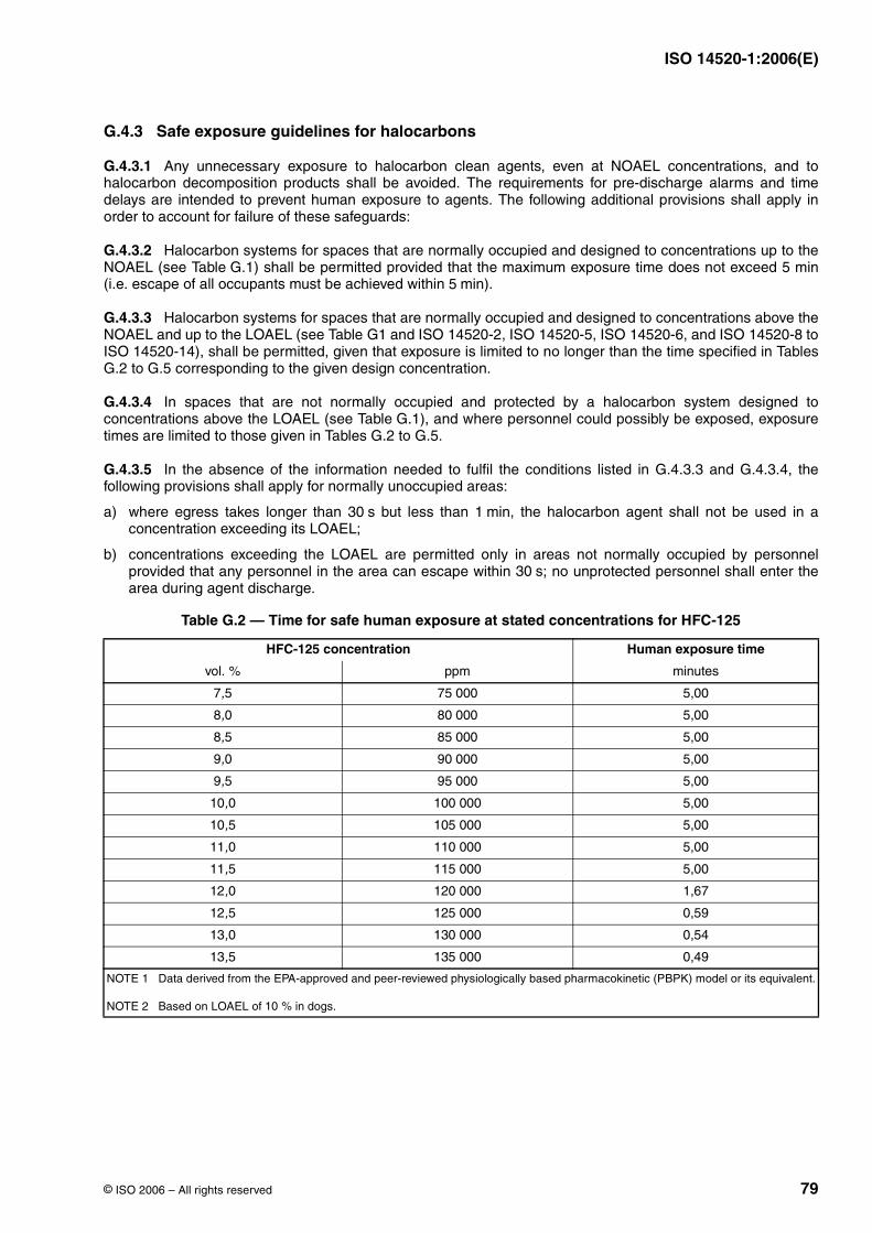
ISO 14520-1:2006(E)
© ISO 2006 – All rights reserved 79
G.4.3 Safe exposure guidelines for halocarbons
G.4.3.1 Any unnecessary exposure to halocarbon clean agents, even at NOAEL concentrations, and tohalocarbon decomposition products shall be avoided. The requirements for pre-discharge alarms and timedelays are intended to prevent human exposure to agents. The following additional provisions shall apply inorder to account for failure of these safeguards:
G.4.3.2 Halocarbon systems for spaces that are normally occupied and designed to concentrations up to theNOAEL (see Table G.1) shall be permitted provided that the maximum exposure time does not exceed 5 min(i.e. escape of all occupants must be achieved within ).
G.4.3.3 Halocarbon systems for spaces that are normally occupied and designed to concentrations above theNOAEL and up to the LOAEL (see Table G1 and ISO 14520-2, ISO 14520-5, ISO 14520-6, and ISO 14520-8 toISO 14520-14), shall be permitted, given that exposure is limited to no longer than the time specified in TablesG.2 to G.5 corresponding to the given design concentration.
G.4.3.4 In spaces that are not normally occupied and protected by a halocarbon system designed toconcentrations above the LOAEL (see Table G.1), and where personnel could possibly be exposed, exposuretimes are limited to those given in Tables G.2 to G.5.
G.4.3.5 In the absence of the information needed to fulfil the conditions listed in G.4.3.3 and G.4.3.4, thefollowing provisions shall apply for normally unoccupied areas:
a) where egress takes longer than but less than , the halocarbon agent shall not be used in aconcentration exceeding its LOAEL;
b) concentrations exceeding the LOAEL are permitted only in areas not normally occupied by personnelprovided that any personnel in the area can escape within ; no unprotected personnel shall enter thearea during agent discharge.
Table G.2 — Time for safe human exposure at stated concentrations for HFC-125
HFC-125 concentration Human exposure time
vol. ppm minutes
7,5 75 000 5,00
8,0 80 000 5,00
8,5 85 000 5,00
9,0 90 000 5,00
9,5 95 000 5,00
10,0 100 000 5,00
10,5 105 000 5,00
11,0 110 000 5,00
11,5 115 000 5,00
12,0 120 000 1,67
12,5 125 000 0,59
13,0 130 000 0,54
13,5 135 000 0,49
NOTE 1 Data derived from the EPA-approved and peer-reviewed physiologically based pharmacokinetic (PBPK) model or its equivalent.
NOTE 2 Based on LOAEL of in dogs.
5 min
30 s 1 min
30 s
%
10 %
ISO 14520-1:2006(E)
80 © ISO 2006 – All rights reserved
Table G.3 — Time for safe human exposure at stated concentrations for HFC-227ea
HFC-227ea concentration Human exposure time
vol. ppm minutes
9,0 90 000 5,00
9,5 95 000 5,00
10,0 100 000 5,00
10,5 105 000 5,00
11,0 110 000 1,13
11,5 115 000 0,60
12,0 120 000 0,49
NOTE 1 Data derived from the EPA-approved and peer-reviewed PBPK model or its equivalent.
NOTE 2 Based on LOAEL of in dogs.
Table G.4 — Time for safe human exposure at stated concentrations for HFC-236fa
HFC-236fa concentration Human exposure time
vol. ppm minutes
10,0 100 000 5,00
10,5 105 000 5,00
11,0 110 000 5,00
11,5 115 000 5,00
12,0 120 000 5,00
12,5 125 000 5,00
13,0 130 000 1,65
13,5 135 000 0,92
14,0 140 000 0,79
14,5 145 000 0,64
15,0 150 000 0,49
NOTE 1 Data derived from the EPA-approved and peer-reviewed PBPK model or its equivalent.
NOTE 2 Based on LOAEL of in dogs.
Table G.5 — Time for safe human exposure at stated concentrations for CF3l
HFC-236fa concentration Human exposure time
vol. ppm minutes
0,20 2 000 5,00
0,25 2 500 5,00
0,30 3 000 5,00
0,35 3 500 4,30
0,40 4 000 0,85
0,45 4 500 0,49
0,50 5 000 0,35
NOTE 1 Data derived from the EPA-approved and peer-reviewed PBPK model or its equivalent.
NOTE 2 Based on LOAEL of in dogs.
%
10,5 %
%
15 %
%
0,4 %
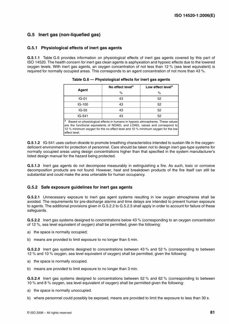
ISO 14520-1:2006(E)
© ISO 2006 – All rights reserved 81
G.5 Inert gas (non-liquefied gas)
G.5.1 Physiological effects of inert gas agents
G.5.1.1 Table G.6 provides information on physiological effects of inert gas agents covered by this part ofISO 14520. The health concern for inert gas clean agents is asphyxiation and hypoxic effects due to the loweredoxygen levels. With inert gas agents, an oxygen concentration of not less than (sea level equivalent) isrequired for normally occupied areas. This corresponds to an agent concentration of not more than .
G.5.1.2 IG-541 uses carbon dioxide to promote breathing characteristics intended to sustain life in the oxygen-deficient environment for protection of personnel. Care should be taken not to design inert gas-type systems fornormally occupied areas using design concentrations higher than that specified in the system manufacturer'slisted design manual for the hazard being protected.
G.5.1.3 Inert gas agents do not decompose measurably in extinguishing a fire. As such, toxic or corrosivedecomposition products are not found. However, heat and breakdown products of the fire itself can still besubstantial and could make the area untenable for human occupancy.
G.5.2 Safe exposure guidelines for inert gas agents
G.5.2.1 Unnecessary exposure to inert gas agent systems resulting in low oxygen atmospheres shall beavoided. The requirements for pre-discharge alarms and time delays are intended to prevent human exposureto agents. The additional provisions given in G.5.2.2 to G.5.2.5 shall apply in order to account for failure of thesesafeguards.
G.5.2.2 Inert gas systems designed to concentrations below (corresponding to an oxygen concentrationof , sea level equivalent of oxygen) shall be permitted, given the following:
a) the space is normally occupied;
b) means are provided to limit exposure to no longer than .
G.5.2.3 Inert gas systems designed to concentrations between and (corresponding to between and oxygen, sea level equivalent of oxygen) shall be permitted, given the following:
a) the space is normally occupied.
b) means are provided to limit exposure to no longer than .
G.5.2.4 Inert gas systems designed to concentrations between and (corresponding to between and oxygen, sea level equivalent of oxygen) shall be permitted given the following:
a) the space is normally unoccupied.
b) where personnel could possibly be exposed, means are provided to limit the exposure to less than .
Table G.6 — Physiological effects for inert gas agents
AgentNo effect levela Low effect levela
IG-01 43 52
IG-100 43 52
IG-55 43 52
IG-541 43 52a Based on physiological effects in humans in hypoxic atmospheres. These valuesare the functional equivalents of NOAEL and LOAEL values and correspond to
minimum oxygen for the no effect level and minimum oxygen for the loweffect level.
12 %43 %
% %
12 % 10 %
43 %12 %
5 min
43 % 52 %12 % 10 %
3 min
52 % 62 %10 % 8 %
30 s

ISO 14520-1:2006(E)
82 © ISO 2006 – All rights reserved
G.5.2.5 Inert gas systems designed to concentrations above (corresponding to oxygen or below, sealevel equivalent of oxygen), shall only be used in normally unoccupied areas where personnel are not exposedto such oxygen depletion. (See Clause 7, Table 5 for atmospheric correction factors.)
62 % 8 %
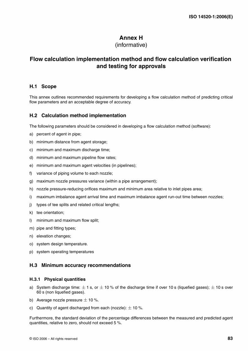
ISO 14520-1:2006(E)
© ISO 2006 – All rights reserved 83
Annex H(informative)
Flow calculation implementation method and flow calculation verification and testing for approvals
H.1 Scope
This annex outlines recommended requirements for developing a flow calculation method of predicting criticalflow parameters and an acceptable degree of accuracy.
H.2 Calculation method implementation
The following parameters should be considered in developing a flow calculation method (software):
a) percent of agent in pipe;
b) minimum distance from agent storage;
c) minimum and maximum discharge time;
d) minimum and maximum pipeline flow rates;
e) minimum and maximum agent velocities (in pipelines);
f) variance of piping volume to each nozzle;
g) maximum nozzle pressures variance (within a pipe arrangement);
h) nozzle pressure-reducing orifices maximum and minimum area relative to inlet pipes area;
i) maximum imbalance agent arrival time and maximum imbalance agent run-out time between nozzles;
j) types of tee splits and related critical lengths;
k) tee orientation;
l) minimum and maximum flow split;
m) pipe and fitting types;
n) elevation changes;
o) system design temperature.
p) system operating temperatures
H.3 Minimum accuracy recommendations
H.3.1 Physical quantities
a) System discharge time: , or of the discharge time if over (liquefied gases); over (non liquefied gases).
b) Average nozzle pressure .
c) Quantity of agent discharged from each (nozzle): .
Furthermore, the standard deviation of the percentage differences between the measured and predicted agentquantities, relative to zero, should not exceed .
± 1 s ± 10 % 10 s ± 10 s60 s
± 10 %
± 10 %
5 %
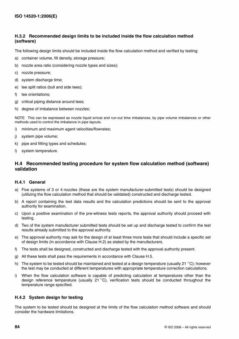
ISO 14520-1:2006(E)
84 © ISO 2006 – All rights reserved
H.3.2 Recommended design limits to be included inside the flow calculation method (software)
The following design limits should be included inside the flow calculation method and verified by testing:
a) container volume, fill density, storage pressure;
b) nozzle area ratio (considering nozzle types and sizes);
c) nozzle pressure;
d) system discharge time;
e) tee split ratios (bull and side tees);
f) tee orientations;
g) critical piping distance around tees;
h) degree of imbalance between nozzles;
NOTE This can be expressed as nozzle liquid arrival and run-out time imbalances, by pipe volume imbalances or othermethods used to control the imbalance in pipe layouts.
i) minimum and maximum agent velocities/flowrates;
j) system pipe volume;
k) pipe and fitting types and schedules;
l) system temperature.
H.4 Recommended testing procedure for system flow calculation method (software) validation
H.4.1 General
a) Five systems of 3 or 4 nozzles (these are the system manufacturer-submitted tests) should be designed(utilizing the flow calculation method that should be validated) constructed and discharge tested.
b) A report containing the test data results and the calculation predictions should be sent to the approvalauthority for examination.
c) Upon a positive examination of the pre-witness tests reports, the approval authority should proceed withtesting.
d) Two of the system manufacturer submitted tests should be set up and discharge tested to confirm the testresults already submitted to the approval authority.
e) The approval authority may ask for the design of at least three more tests that should include a specific setof design limits (in accordance with Clause H.2) as stated by the manufacturers.
f) The tests shall be designed, constructed and discharge tested with the approval authority present.
g) All these tests shall pass the requirements in accordance with Clause H.5.
h) The system to be tested should be maintained and tested at a design temperature (usually ); howeverthe test may be conducted at different temperatures with appropriate temperature correction calculations.
i) When the flow calculation software is capable of predicting calculation at temperatures other than thedesign reference temperature (usually ), verification tests should be conducted throughout thetemperature range specified.
H.4.2 System design for testing
The system to be tested should be designed at the limits of the flow calculation method software and shouldconsider the hardware limitations.
21 ◦C
21 ◦C
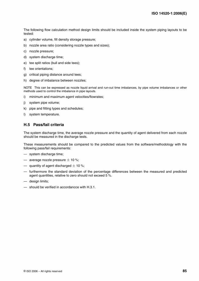
ISO 14520-1:2006(E)
© ISO 2006 – All rights reserved 85
The following flow calculation method design limits should be included inside the system piping layouts to betested:
a) cylinder volume, fill density storage pressure;
b) nozzle area ratio (considering nozzle types and sizes);
c) nozzle pressure;
d) system discharge time;
e) tee split ratios (bull and side tees);
f) tee orientations;
g) critical piping distance around tees;
h) degree of imbalance between nozzles;
NOTE This can be expressed as nozzle liquid arrival and run-out time imbalances, by pipe volume imbalances or othermethods used to control the imbalance in pipe layouts.
i) minimum and maximum agent velocities/flowrates;
j) system pipe volume;
k) pipe and fitting types and schedules;
l) system temperature.
H.5 Pass/fail criteria
The system discharge time, the average nozzle pressure and the quantity of agent delivered from each nozzleshould be measured in the discharge tests.
These measurements should be compared to the predicted values from the software/methodology with thefollowing pass/fail requirements:
— system discharge time;
— average nozzle pressure ;
— quantity of agent discharged ;
— furthermore the standard deviation of the percentage differences between the measured and predictedagent quantities, relative to zero should not exceed .
— design limits;
— should be verified in accordancce with H.3.1.
± 10 %
± 10 %
5 %

ISO 14520-1:2006(E)
ICS 13.220.10Price based on 85 pages
© ISO 2006 – All rights reserved

![Plastics piping systems for the supply of gaseous fuels — …_Plastics... · 2018. 5. 24. · EN 1555-1, EN 1555-2 and prEN 1555-4 [9]. Characteristics for fitness for purpose are](https://img.pdfslide.fr/doc/110x75/60cfa5b7d3f65b2032720d4d/plastics-piping-systems-for-the-supply-of-gaseous-fuels-a-plastics-2018.jpg)