Embed Size (px)
Citation preview
Ice-Templating of Alumina Suspensions: Effect of Supercoolingand Crystal Growth During the Initial Freezing Regime
Audrey Lasalle,‡,† Christian Guizard,‡ Jerome Leloup,‡ Sylvain Deville,‡ Eric Maire,§ Agnes Bogner,§
Catherine Gauthier,§ Jerome Adrien,§ and Loıc Courtois§
‡Laboratoire de Synthese et Fonctionnalisation des Ceramiques, UMR 3080 CNRS/Saint-Gobain, 84306 Cavaillon, France
§INSA-Lyon, MATEIS CNRS UMR5510, Universite de Lyon, F-69621 Villeurbanne, France
We investigate the ice-templating behavior of alumina suspen-
sions by in situ X-ray radiography and tomography. We focusherein on the formation and structure of the transitional zone,
occurring during the initial instants of freezing. For many
applications, this zone is undesirable as the resulting porosity isheterogeneous in size, morphology, and orientation. We investi-
gate the influence of the composition of alumina suspensions on
the formation of the transitional zone. Alumina particles are
dispersed by three different dispersants, in various quantities,or by hydrochloric acid. We show that the dimensions and the
morphology of the transitional zone are determined by the
growth of large dendritic ice-crystals growing in a supercooled
state much faster than the cellular freezing front. When thefreezing temperature decreases, the degree of supercooling
increases. This results in an initial faster freezing front velocity
and increase in the dimensions of the transitional zone. It istherefore possible to adjust the dimensions of the transitional
zone by changing the composition of alumina suspensions. The
counter-ion Na+ has the most dramatic effect on the freezing
temperature of suspensions, yielding a predominance of cellularice crystals instead of the usual lamellar crystals.
I. Introduction
I CE-TEMPLATING is a shaping process used to obtain porousmaterials by freezing a suspension of particles and subse-
quently removing the ice-crystals by freeze-drying. Thepotential interest for ceramic materials was discovered byFukasawa in 2001.1 This process consists of pouring a cera-mic suspension into a mold, usually frozen by the bottom.Ice crystals grow unidirectionally, through the suspension,rejecting and concentrating particles in the intercrystalsspace. Ice crystals are then removed by sublimation. A por-ous green body is thus obtained where the pores are a directreplica of the ice crystals. The green body can then be con-solidated by sintering,2 if needed. Different pore sizes (from 1to 100 lm), porosity (from 10% to 90%), and pore morpho-logies can be obtained. Such materials are currently consid-ered for biomedical applications,3 active substance delivery,4
acoustic insulation,5 SOFC,6,7 or piezoelectric applications.8
The present study rationalizes our early work about thetransient regime.9 We have shown that, during ice-templat-ing, freezing occurs in two stages: an initial transient regimefollowed by a steady state.10 During the initial instants offreezing, the freezing front advances quickly in the direction
Z imposed by the thermal gradient. The microstructureobtained is characterized by two populations of ice crystals:R-crystals (R for randomly oriented) and Z-crystals (forlamellar ice crystals, oriented along the Z direction). We con-sidered that the ice crystals are oriented when they growaccording to the thermal gradient, a direction referred to asdirection Z. Due to their different orientation and morphol-ogy, these two populations of crystals do not concentrateceramic particles with the same efficiency. We have shownthat the sudden extinction of the R-crystals marks the end ofthe transitional zone, leaving only lamellar crystals growinginto the suspension [figure 5 of the Ref. (9)]. This corre-sponds to the beginning of the steady state of the freezing.This study has defined the morphological characteristics ofthe transition zone, but the understanding of its formationmechanism has yet to be explained and the eventual role ofthe composition of the suspension assessed.
For many applications, a continuous porosity is desired.The presence of a graded structure, corresponding to thistransitional zone, can be problematic. For instance, in theSOFC design currently investigated by NASA,7 the transi-tional zone limits the efficiency of the infiltration of the por-ous electrodes obtained by ice-templating.
Several parameters were identified to have an influenceover this transient regime, such as the particle size,11 theshape of the cooling ramp (linear, constant, parabolic),12 orthe application of an electric field during freezing.13 In thepresent article, we show that the characteristics of this tran-sient regime are controlled by the initial supercooling condi-tions. We assess the influence of the composition of aluminasuspensions, stabilized with various dispersants. We use X-ray radiography and tomography to respectively observe thefreezing front behavior and characterize the resulting frozenmicrostructure. Although the 1.4 lm resolution does not per-mit to resolve individual particles, it is high enough to pro-vide an accurate observation of ice crystals and concentratedparticles’ regions.
II. Experimental Procedure
(1) Suspensions PreparationAlumina powder (Ceralox SPA 0.5; Sasol, Tucson, AZ),D50 = 0.3 lm, with a specific surface area of 8 m²/g, is dis-persed in distilled water with an organic dispersant or withhydrochloric acid. The alumina content is always 32 vol%,unless specified. Thirty-two volume percent is an arbitrarychosen value, but including in the range of alumina contentstraditionally used for slip-casted and ice-templated materials.We have prepared some suspensions with a higher aluminacontent of 50 vol% too to observe the effect of the solid con-tent on freezing. This value is under the critical alumina con-tent, 56.6 vol%, above which the particles are no longerrejected by ice crystals but trapped into ice.14 Three sortsof suspensions are prepared. Some contain an ammonium
H.-E. Kim—contributing editor
Manuscript No. 29789. Received May 27, 2011; approved November 06, 2011.†Author to whom correspondence should be addressed. e-mail: lasalle.audrey@
gmail.com
799
J. Am. Ceram. Soc., 95 [2] 799–804 (2012)
DOI: 10.1111/j.1551-2916.2011.04993.x
© 2011 The American Ceramic Society
Journal
polymethacrylate as dispersant (Darvan CN; Vanderbilt,Norwalk, CT), others contain a sodium polymethacrylate(Darvan 7 Ns; Vanderbilt), and the third type of suspensionis dispersed by an ammonium polyacrylate (Darvan 821A;Vanderbilt). These organic dispersants are respectively referredin text as D[NH4
+], D[Na+], and d[NH4+]. They are intro-
duced with a quantity varying from 0.2 to 2 wt%. Suspen-sions prepared with hydrochloric acid (HCl) contain3.1 9 10�2 or 6 9 10�2 mol/L of HCl. Dispersant (or acid)is stirred with distilled water for 30 min and then the alu-mina powder is added. Alumina suspensions are ball-milledfor 40 h, de-aired before being ice-templated. The dispersantquantity is expressed in weight percent related to the mass ofdried powder. The various suspensions investigated are sum-marized in Table I.
(2) Freezing SetUpSuspensions are introduced into a polypropylene mold of3 mm in diameter, with a syringe. A particular attention ispaid to avoid air bubbles introduction in suspension. Themold is placed on the top of a copper finger cooled from thebottom by a liquid nitrogen circulation. The cooling rate iscontrolled by the liquid nitrogen flow and the temperatureprofile is registered during experiment, attributable to a ther-mocouple located near the copper finger surface. The setupof freezing was previously described.9 Our measurementshave shown that alumina suspensions can be frozen with thissetup at a cooling rate ranging from 3 to 5.3°C/min.
(3) Freezing-Temperature MeasurementTwo techniques were used for the freezing-temperature mea-surement. Cold-Differential Scanning Calorimetry (DSCQ100; TA Instruments, Guyancourt, France) was carried outon a constant 15 lL volume, introduced into a capsule. Thecapsule is cooled at 2 or 5°C/min. The freezing temperatureis defined as the beginning of the endothermic peak, deter-mined by the fitting tangent method. We also use a thermo-couple located at the surface of the copper finger during thefreezing experiment. In this case, the freezing temperaturecorresponds to the instant where the first ice crystals areobservable on the radiographs.
(4) X-Ray Radiography and TomographyX-ray radiography and tomography experiments were per-formed at ESRF (Grenoble, France) on the beamline ID-19.A monochromatic high coherent X-ray beam with an energyof 20.5 keV passes through the sample. A CDD camera with2048 9 2048 sensitive elements is placed at 20 mm behindthe sample. The advancement of the freezing front is fol-lowed by radiography with a spatial resolution of 2.8 lm. Asequence of pictures is acquired without moving the sampleto follow the advancement of the freezing front, so that wecan accurately measure the freezing front velocity. In radiog-raphy, the gray level is proportional to the transmission ofX-rays, i.e. high values of gray levels correspond to a zone
with low absorption of X-rays, that is, ice in our case. Lowgray levels correspond to the particle-rich phase.
The interest and limitations of the in situ X-ray tomogra-phy in the field of materials have been demonstrated byBuffiere & co. based on the observations of the mechanicalbehavior of several materials.15 Tomography consists ofacquiring radiographies at different viewing angles during therotation of a sample over 180°. To ensure a good reconstruc-tion, the microstructure must not evolve during acquisition.If we would perform a tomography acquisition during thefreezing, as the scan takes about 10 min, the freezing frontwould move and the microstructure would evolve during thescan, leading to a poor reconstruction. We therefore observethe microstructure when the sample is completely frozen. Thefrozen sample is maintained at a constant temperature duringthe scan. The spatial resolution is 1.4 lm. After a computertreatment, a 3-D map of the absorption coefficient isobtained. Contrarily to radiography, the gray level is propor-tional to the absorption of X-rays. High gray levels corre-spond to the phase with the higher atomic number, theparticle-rich phase in our case.
(5) Image AnalysisThe dimensions (height) of transitional zone are measuredfrom the tomography reconstruction. A sequence of 1600reconstructed slices of 2048 9 2048 voxels is obtained. Suchlarge files are difficult to handle. The reconstructed imagesare first scaled to a resolution of 4.7 lm in the X and Ydirections perpendicular to the freezing direction. The resolu-tion is preserved in the Z direction to achieve a better accu-racy in the measurements of the height of the transitionalzone. We then restrict our measurement to a square of400 9 400 voxels in the X and Y directions. Then, each pic-ture in gray levels is transformed into a binary picture usinga segmentation criterion, provided as a plug-in in the soft-ware Fiji.16 A scan of 1600 binarized pictures is obtained. Byimage analysis, we calculate the fraction of ice and the frac-tion of the particle-rich phase. By reporting the variation ofthe particle-rich phase fraction as a function of position Z,we can determine the height of the transitional zone. It ischaracterized by a rapid decrease in the particle-rich phasefraction, followed by an increase [figure 5 of Ref. (9)]. Thissudden variation originates from the extinction of R-crystals,which concentrate particles in the Z direction, while Z-crys-tals concentrate them mostly in the XY plane, perpendicularto the temperature gradient.
III. Results and Discussion
(1) Influence of Ion on the Freezing TemperatureThe freezing temperatures lie in the range from �10°C to�20°C, for a cooling rate included between 2 and 5.3°C/minregardless of the composition and the experimental technique(Fig. 1). We can distinguish two ranges of freezing tempera-ture, in the limit of the tested dispersant concentrations, 0.2–2 wt% related to the alumina weight content. First, the �10°C to �15°C range, for example, with the introduction ofd[NH4
+] or HCl with 32 vol% of alumina particles and cer-tain values concerning D[NH4
+], with 32 or 50 vol% of alu-mina particles. The second range corresponds to the �15°Cto �20°C range. We measured the freezing temperature forsuspensions containing dispersant between 0.2 and 2 wt%,where the dispersion state of suspensions could be impacted.The dispersion state was assessed by viscosity and zetapotential measurements, not presented herein. No strongagglomeration was observed since the zeta potential wasfound in the �45 to �75 mV range, sufficiently high toensure a stable state and high repulsions between particles.We did not represent the freezing temperature as a functionof the dispersant concentration as no clear trend could beidentified so far. It appears that the counter-ion Na+ used in
Table I. Composition of the Ice-Templated
Alumina Suspensions
Alumina content
(vol%) Nature of additive Quantity of additive
32 D[NH4+] 0.2–0.4–0.7–1–2 wt%
50 D[NH4+] 0.2–2 wt%
32 D[Na+] 0.2–2 wt%32 d[NH4
+] 0.2–1 wt%32 HCI 3.1–6 9 10�2 mol/L
800 Journal of the American Ceramic Society—Lasalle et al. Vol. 95, No. 2
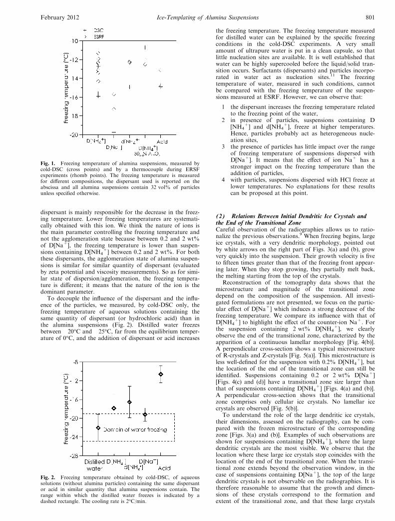
dispersant is mainly responsible for the decrease in the freez-ing temperature. Lower freezing temperatures are systemati-cally obtained with this ion. We think the nature of ions isthe main parameter controlling the freezing temperature andnot the agglomeration state because between 0.2 and 2 wt%of D[Na+], the freezing temperature is lower than suspen-sions containing D[NH4
+] between 0.2 and 2 wt%. For boththese dispersants, the agglomeration state of alumina suspen-sions is similar for similar quantity of dispersant (evaluatedby zeta potential and viscosity measurements). So as for simi-lar state of dispersion/agglomeration, the freezing tempera-ture is different; it means that the nature of the ion is thedominant parameter.
To decouple the influence of the dispersant and the influ-ence of the particles, we measured, by cold-DSC only, thefreezing temperature of aqueous solutions containing thesame quantity of dispersant (or hydrochloric acid) than inthe alumina suspensions (Fig. 2). Distilled water freezesbetween �20°C and �25°C, far from the equilibrium temper-ature of 0°C, and the addition of dispersant or acid increases
the freezing temperature. The freezing temperature measuredfor distilled water can be explained by the specific freezingconditions in the cold-DSC experiments. A very smallamount of ultrapure water is put in a clean capsule, so thatlittle nucleation sites are available. It is well established thatwater can be highly supercooled before the liquid/solid tran-sition occurs. Surfactants (dispersants) and particles incorpo-rated in water act as nucleation sites.11 The freezingtemperature of water, measured in such conditions, cannotbe compared with the freezing temperature of the suspen-sions measured at ESRF. However, we can observe that:
1 the dispersant increases the freezing temperature relatedto the freezing point of the water,
2 in presence of particles, suspensions containing D[NH4
+] and d[NH4+], freeze at higher temperatures.
Hence, particles probably act as heterogeneous nucle-ation sites,
3 the presence of particles has little impact over the rangeof freezing temperature of suspensions dispersed withD[Na+]. It means that the effect of ion Na+ has astronger impact on the freezing temperature than theaddition of particles,
4 with particles, suspensions dispersed with HCl freeze atlower temperatures. No explanations for these resultscan be proposed at this point.
(2) Relations Between Initial Dendritic Ice Crystals andthe End of the Transitional ZoneCareful observation of the radiographies allows us to ratio-nalize the previous observations.9 When freezing begins, largeice crystals, with a very dendritic morphology, pointed outby white arrows on the right part of Figs. 3(a) and (b), growvery quickly into the suspension. Their growth velocity is fiveto fifteen times greater than that of the freezing front appear-ing later. When they stop growing, they partially melt back,the melting starting from the top of the crystals.
Reconstruction of the tomography data shows that themicrostructure and magnitude of the transitional zonedepend on the composition of the suspension. All investi-gated formulations are not presented, we focus on the partic-ular effect of D[Na+] which induces a strong decrease of thefreezing temperature. We compare its influence with that ofD[NH4
+] to highlight the effect of the counter-ion Na+. Forthe suspension containing 2 wt% D[NH4
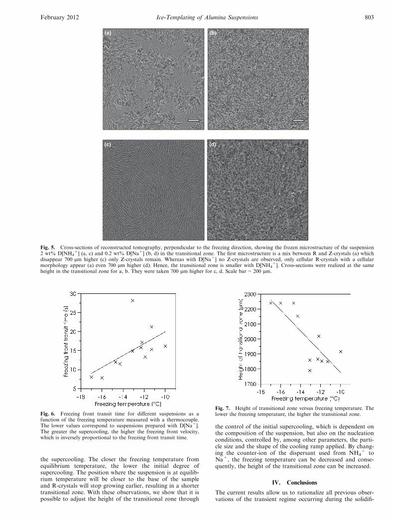
+], we clearlyobserve the end of the transitional zone, characterized by theapparition of a continuous lamellar morphology [Fig. 4(b)].A perpendicular cross-section shows a typical microstructureof R-crystals and Z-crystals [Fig. 5(a)]. This microstructure isless well-defined for the suspension with 0.2% D[NH4
+], butthe location of the end of the transitional zone can still beidentified. Suspensions containing 0.2 or 2 wt% D[Na+][Figs. 4(c) and (d)] have a transitional zone size larger thanthat of suspensions containing D[NH4
+] [Figs. 4(a) and (b)].A perpendicular cross-section shows that the transitionalzone comprises only cellular ice crystals. No lamellar icecrystals are observed [Fig. 5(b)].
To understand the role of the large dendritic ice crystals,their dimensions, assessed on the radiography, can be com-pared with the frozen microstructure of the correspondingzone [Figs. 3(a) and (b)]. Examples of such observations areshown for suspensions containing D[NH4
+], where the largedendritic crystals are the most visible. We observe that thelocation where these large ice crystals stop coincides with thelocation of the end of the transitional zone. When the transi-tional zone extends beyond the observation window, in thecase of suspensions containing D[Na+], the top of the largedendritic crystals is not observable on the radiographies. It istherefore reasonable to assume that the growth and dimen-sions of these crystals correspond to the formation andextent of the transitional zone, and that these large crystals
Fig. 1. Freezing temperature of alumina suspensions, measured bycold-DSC (cross points) and by a thermocouple during ERSFexperiments (rhomb points). The freezing temperature is measuredfor different compositions, the dispersant used is reported on theabscissa and all alumina suspensions contain 32 vol% of particlesunless specified otherwise.
Fig. 2. Freezing temperature obtained by cold-DSC, of aqueoussolutions (without alumina particles) containing the same dispersantor acid in similar quantity that alumina suspensions contain. Therange within which the distilled water freezes is indicated by adashed rectangle. The cooling rate is 2°C/min.
February 2012 Ice-Templating of Alumina Suspensions 801
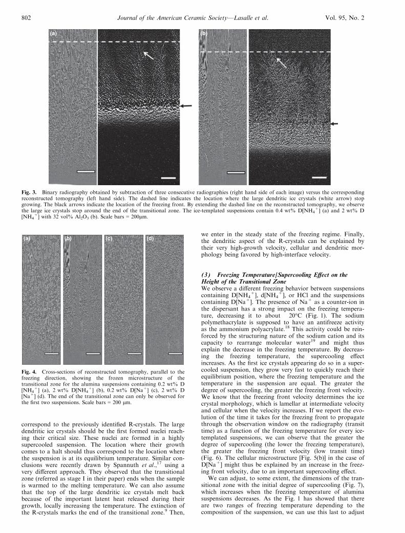
correspond to the previously identified R-crystals. The largedendritic ice crystals should be the first formed nuclei reach-ing their critical size. These nuclei are formed in a highlysupercooled suspension. The location where their growthcomes to a halt should thus correspond to the location wherethe suspension is at its equilibrium temperature. Similar con-clusions were recently drawn by Spannuth et al.,17 using avery different approach. They observed that the transitionalzone (referred as stage I in their paper) ends when the sampleis warmed to the melting temperature. We can also assumethat the top of the large dendritic ice crystals melt backbecause of the important latent heat released during theirgrowth, locally increasing the temperature. The extinction ofthe R-crystals marks the end of the transitional zone.9 Then,
we enter in the steady state of the freezing regime. Finally,the dendritic aspect of the R-crystals can be explained bytheir very high-growth velocity, cellular and dendritic mor-phology being favored by high-interface velocity.
(3) Freezing Temperature/Supercooling Effect on theHeight of the Transitional ZoneWe observe a different freezing behavior between suspensionscontaining D[NH4
+], d[NH4+], or HCl and the suspensions
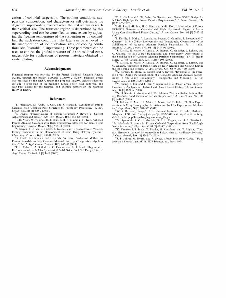
containing D[Na+]. The presence of Na+ as a counter-ion inthe dispersant has a strong impact on the freezing tempera-ture, decreasing it to about �20°C (Fig. 1). The sodiumpolymethacrylate is supposed to have an antifreeze activityas the ammonium polyacrylate.18 This activity could be rein-forced by the structuring nature of the sodium cation and itscapacity to rearrange molecular water19 and might thusexplain the decrease in the freezing temperature. By decreas-ing the freezing temperature, the supercooling effectincreases. As the first ice crystals appearing do so in a super-cooled suspension, they grow very fast to quickly reach theirequilibrium position, where the freezing temperature and thetemperature in the suspension are equal. The greater thedegree of supercooling, the greater the freezing front velocity.We know that the freezing front velocity determines the icecrystal morphology, which is lamellar at intermediate velocityand cellular when the velocity increases. If we report the evo-lution of the time it takes for the freezing front to propagatethrough the observation window on the radiography (transittime) as a function of the freezing temperature for every ice-templated suspensions, we can observe that the greater thedegree of supercooling (the lower the freezing temperature),the greater the freezing front velocity (low transit time)(Fig. 6). The cellular microstructure [Fig. 5(b)] in the case ofD[Na+] might thus be explained by an increase in the freez-ing front velocity, due to an important supercooling effect.
We can adjust, to some extent, the dimensions of the tran-sitional zone with the initial degree of supercooling (Fig. 7),which increases when the freezing temperature of aluminasuspensions decreases. As the Fig. 1 has showed that thereare two ranges of freezing temperature depending to thecomposition of the suspension, we can use this last to adjust
(a) (b)
Fig. 3. Binary radiography obtained by subtraction of three consecutive radiographies (right hand side of each image) versus the correspondingreconstructed tomography (left hand side). The dashed line indicates the location where the large dendritic ice crystals (white arrow) stopgrowing. The black arrows indicate the location of the freezing front. By extending the dashed line on the reconstructed tomography, we observethe large ice crystals stop around the end of the transitional zone. The ice-templated suspensions contain 0.4 wt% D[NH4
+] (a) and 2 wt% D[NH4
+] with 32 vol% Al2O3 (b). Scale bars = 200lm.
(a) (b) (c) (d)
Fig. 4. Cross-sections of reconstructed tomography, parallel to thefreezing direction, showing the frozen microstructure of thetransitional zone for the alumina suspensions containing 0.2 wt% D[NH4
+] (a), 2 wt% D[NH4+] (b), 0.2 wt% D[Na+] (c), 2 wt% D
[Na+] (d). The end of the transitional zone can only be observed forthe first two suspensions. Scale bars = 200 lm.
802 Journal of the American Ceramic Society—Lasalle et al. Vol. 95, No. 2
the supercooling. The closer the freezing temperature fromequilibrium temperature, the lower the initial degree ofsupercooling. The position where the suspension is at equilib-rium temperature will be closer to the base of the sampleand R-crystals will stop growing earlier, resulting in a shortertransitional zone. With these observations, we show that it ispossible to adjust the height of the transitional zone through
the control of the initial supercooling, which is dependent onthe composition of the suspension, but also on the nucleationconditions, controlled by, among other parameters, the parti-cle size and the shape of the cooling ramp applied. By chang-ing the counter-ion of the dispersant used from NH4
+ toNa+, the freezing temperature can be decreased and conse-quently, the height of the transitional zone can be increased.
IV. Conclusions
The current results allow us to rationalize all previous obser-vations of the transient regime occurring during the solidifi-
(a) (b)
(c) (d)
Fig. 5. Cross-sections of reconstructed tomography, perpendicular to the freezing direction, showing the frozen microstructure of the suspension2 wt% D[NH4
+] (a, c) and 0.2 wt% D[Na+] (b, d) in the transitional zone. The first microstructure is a mix between R and Z-crystals (a) whichdisappear 700 lm higher (c) only Z-crystals remain. Whereas with D[Na+] no Z-crystals are observed, only cellular R-crystals with a cellularmorphology appear (a) even 700 lm higher (d). Hence, the transitional zone is smaller with D[NH4
+]. Cross-sections were realized at the sameheight in the transitional zone for a, b. They were taken 700 lm higher for c, d. Scale bar = 200 lm.
Fig. 6. Freezing front transit time for different suspensions as afunction of the freezing temperature measured with a thermocouple.The lower values correspond to suspensions prepared with D[Na+].The greater the supercooling, the higher the freezing front velocity,which is inversely proportional to the freezing front transit time.
Fig. 7. Height of transitional zone versus freezing temperature. Thelower the freezing temperature, the higher the transitional zone.
February 2012 Ice-Templating of Alumina Suspensions 803
cation of colloidal suspension. The cooling conditions, sus-pensions composition, and characteristics will determine thedegree of supercooling reached when the first ice nuclei reachtheir critical size. The transient regime is determined by thissupercooling, and can be controlled to some extent by adjust-ing the freezing temperature of the suspension or by control-ling the nucleation conditions. The later can be achieved bythe incorporation of ice nucleation sites, or cooling condi-tions less favorable to supercooling. These parameters can beused to control the graded structure of the transitional zone,undesirable for applications of porous materials obtained byice-templating.
Acknowledgments
Financial support was provided by the French National Research Agency(ANR), through the project NACRE BLAN07-2_192446. Beamline accesswas provided by the ERSF, under the proposal MA997. Acknowledgmentsare due to local staff of the beamline: Elodie Boller, Paul Tafforeau, andJean-Paul Valade for the technical and scientific support on the beamlineID-19 at ERSF.
References
1T. Fukasawa, M. Ando, T. Ohji, and S. Kanzaki, “Synthesis of PorousCeramics with Complex Pore Structure by Freeze-dry Processing,” J. Am.Ceram. Soc., 84 [1] 230–2 (2001).
2S. Deville, “Freeze-Casting of Porous Ceramics: A Review of CurrentAchievements and Issues,” Adv. Eng. Mater., 10 [3] 155–69 (2008).
3B.-H. Yoon, W.-Y. Choi, H.-E. Kim, J.-H. Kim, and Y.-H. Koh, “AlignedPorous Alumina Ceramics with High Compressive Strengths for Bone TissueEngineering,” Scripta Mater., 58 [7] 537–40 (2008).
4A. Szepes, J. Ulrich, Z. Farkas, J. Kovacs, and P. Szabo-Revesz, “Freeze-Casting Technique in the Development of Solid Drug Delivery Systems,”Chem. Eng. Process., 46 [3] 230–8 (2007).
5G. Frank, E. Christian, and D. Koch, “A Novel Production Method forPorous Sound-Absorbing Ceramic Material for High-Temperature Applica-tions,” Int. J. Appl. Ceram. Technol., 8 [3] 646–52 (2011).
6T. L. Cable, J. A. Setlock, S. C. Farmer, and A. J. Eckel, “RegenerativePerformance of the NASA Symmetrical Solid Oxide Fuel Cell Design,” Int. J.Appl. Ceram. Technol., 8 [1] 1–12 (2010).
7T. L. Cable and S. W. Sofie, “A Symmetrical, Planar SOFC Design forNASA’s High Specific Power Density Requirements,” J. Power Sources, 174[1] 221–7 (2007).
8S.-H. Lee, S.-H. Jun, H.-E. Kim, and Y.-H. Koh, “Fabrication of PorousPZT-PZN Piezoelectric Ceramics with High Hydrostatic Figure of MeritsUsing Camphene-Based Freeze Casting,” J. Am. Ceram. Soc., 90 [9] 2807–13(2007).
9S. Deville, E. Maire, A. Lasalle, A. Bogner, C. Gauthier, J. Leloup, and C.Guizard, “In Situ X-Ray Radiography and Tomography Observations of theSolidification of Aqueous Alumina Particle Suspensions. Part I: InitialInstants,” J. Am. Ceram. Soc., 92 [11] 2489–96 (2009).
10S. Deville, E. Maire, A. Lasalle, A. Bogner, C. Gauthier, J. Leloup, andC. Guizard, “In Situ X-Ray Radiography and Tomography Observations ofthe Solidification of Aqueous Alumina Particles Suspensions. Part II: SteadyState,” J. Am. Ceram. Soc., 92 [11] 2497–503 (2009).
11S. Deville, E. Maire, A. Lasalle, A. Bogner, C. Gauthier, J. Leloup, andC. Guizard, “Influence of Particle Size on Ice Nucleation and Growth Duringthe Ice-Templating Process,” J. Am. Ceram. Soc., 93 [9] 2507–10 (2010).
12A. Bareggi, E. Maire, A. Lasalle, and S. Deville, “Dynamics of the Freez-ing Front During the Solidification of a Colloidal Alumina Aqueous Suspen-sions: In Situ X-ray Radiography, Tomography and Modeling,” J. Am.Ceram. Soc., 94 [10] 3570–8 (2011).
13Y. Zhang, L. Hu, and J. Han, “Preparation of a Dense/Porous BiLayeredCeramic by Applying an Electric Field During Freeze Casting,” J. Am. Ceram.Soc., 92 [8] 1874–6 (2009).
14N. O. Shanti, K. Araki, and J. W. Halloran, “Particle Redistribution Dur-ing Dendritic Solidification of Particle Suspensions,” J. Am. Ceram. Soc., 89[8] 2444–7 (2006).
15J. Buffiere, E. Maire, J. Adrien, J. Masse, and E. Boller, “In Situ Experi-ments with X ray Tomography: An Attractive Tool for Experimental Mechan-ics,” Exp. Mech., 50 [3] 289–305 (2010).
16W. S. Rasband, ImageJ, U. S. National Institutes of Health, Bethesda,Maryland, USA, http://imagej.nih.gov/ij/, 1997–2011 and http://pacific.mpi-cbg.de/wiki/index.php/Trainable_Segmentation_Plugin
17M. Spannuth, S. G. J. Mochrie, S. S. L. Peppin, and J. S. Wettlaufer,“Particle-Scale Structure in Frozen Colloidal Suspensions from Small-AngleX-ray Scattering,” Phys. Rev. E, 83 [2] 021402 (2011).
18K. Funakoshi, T. Inada, T. Tomita, H. Kawahara, and T. Miyata, “Ther-mal Hysteresis Induced by Ammonium Polyacrylate as Antifreeze Polymer,”J. Cryst. Growth, 310 [14] 3342–7 (2008).
19J. P. Jolivet, M. Henry, and J. Livage, (From Solution to Oxide) “De lasolution a l’oxyde”. pp. 387 in EDP Sciences. ed., Paris, 1994. h
804 Journal of the American Ceramic Society—Lasalle et al. Vol. 95, No. 2


![IJMPERD - Comparative Study by Numerical Investigation of ......0.25 MWCNTs-0.035 GNPs/water hybrid nanofluids. Kaska et al. [12] enhanced the heat transfer of water by using alumina](https://img.pdfslide.fr/doc/110x75/60b9c51307e90c51185cd97d/ijmperd-comparative-study-by-numerical-investigation-of-025-mwcnts-0035.jpg)