Embed Size (px)
Citation preview
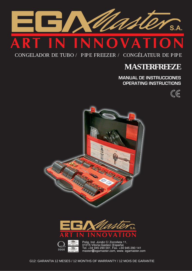
MASTERFREEZE
CONGELADOR DE TUBO / PIPE FREEZER / CONGÉLATEUR DE PIPE
G12: GARANTIA 12 MESES / 12 MONTHS OF WARRANTY / 12 MOIS DE GARANTIE
• CARACTERISTICAS TÉCNICAS
.::Capacidad: Congela todo tipo de líquidos, incluso a alta presión, en el interior de tubos de acero, cobre, fundición, aluminio o plástico…
.::Diámetros de tubo a congelar: EUR
-Acero: desde 1/8” hasta 2” -Cobre: desde 10 mm hasta 42 mm USA -Acero: desde 1/8” hasta 2” -Cobre: desde 1/4” hasta 2”
.::Peso conjunto: 5Kg.
• EQUIPAMIENTO DE LA MÁQUINA
- Maleta de plástico - 2 mangueras en espiral - 1 conector bombona-mangueras (distribuidor T) - 1 tapón obturador (tuerca de cierre) - 1 destornillador punta esfera (4mm) - 2 cabezales de congelación para cada tamaño dependiendo del equipo escogido (EUR o USA)
• GARANTÍA
Egamaster garantiza al comprador de ésta máquina la garantía total durante 12 meses de las piezas con defectos de fabricación. Esta garantía no cubre aquellas piezas que por su uso normal tienen un desgaste.
• NOTA
Para obtener la validez de la garantía, es absolutamente imprescindible que complete y remita a Egamaster el documento de “CERTIFICADO DE GARANTIA”, dentro de los siete dias a partir de la fecha de compra.
• CONGELADOR DE TUBO Este congelador de tubos puede utilizarse para congelar cualquier tipo de líquidos, incluso a alta presión, dentro de tuberías de acero, cobre, hierro fundido, aluminio oplástico en un rango desde 1/8” hasta 2” (10-60mm). Utiliza dióxido de carbono (CO2) comercial.
El congelador de tubos está diseñado para brindar al usuario años de servicio útil y sin
problemas. Teniendo en cuenta que ninguna herramienta es mejor que su equipo, se recomienda leer atentamente las instrucciones antes de utilizar su máquina. Esto le permitirá trabajar con el congelador de tubos de forma más eficiente y provechosa. De no cumplir estas instrucciones, se pueden llegar a provocar daños en el equipo.
En definitiva, estas máquinas compactas, fáciles de usar y de gran eficacia de trabajo son extensamente aplicadas en industrias de instalación y construcción para operaciones profesionales de reparación y mantenimiento. • MEDIDAS DE SEGURIDAD BÁSICAS
1) Utilice el congelador de tubos sólo para el propósito para el cual ha sido diseñado, teniendo el cuidado de poner en práctica las medidas generales para prevención de accidentes
2) Mantenga el área de trabajo limpia. El desorden puede ser peligroso. 3) Evite líquidos, o gases inflamables peligrosos.
4) Suministre una iluminación adecuada al área de trabajo.
5) Utilice ropa de trabajo adecuada. Si tiene el cabello largo, manténgalo recogido. Quítese
todo tipo de joyas o cualquier otro objeto similar.
6) Utilice EPI´s (Equipos de Protección Individual) como por ejemplo: lentes de seguridad, gafas de goma...
7) Coloque abrazaderas en la pieza que va a trabajar, no la agarre con las manos.
8) Revise de vez en cuando la unidad para verificar que no tenga daños y que está
funcionando debidamente.
9) Reemplace las piezas que muestren desgaste lo más rápido posible.
10) Por razones de seguridad personal, para asegurar el correcto funcionamiento del congelador de tubos y para garantizar el cumplimiento de las bases de la garantía con respecto a reclamos, utilice sólo repuestos y accesorios genuinos.
11) Todos los trabajos de reparación deben llevarse a cabo en establecimientos de
reparación autorizados.
12) Queda prohibido cualquier tipo de modificación no autorizada del congelador de tubos por razones de seguridad.
• MEDIDAS DE SEGURIDAD ESPECÍFICAS
1) El dióxido de carbono se debe sacar del cilindro en estado líquido, para poder producir hielo seco. Por esta razón, sólo se pueden utilizar cilindros equipados con un tubo de inmersión.
2) Nunca desconecte un reductor de presión al cilindro. 3) Mantenga el cilindro en posición verticarl y asegúrelo para garantizar que no se voltee 4) El cilindro de dióxido de carbono no debe nunca vaciarse totalmente 5) No interfiera con las boquillas, cabezales de congelación o válvulas, incluyendo las
válvulas del cilindro. 6) Trabaje sólo dentro de un área debidamente ventilada. El dióxido de carbono no es
tóxico, ni inflamable; sin embargo, es más pesado que el aire y si la ventailación es inadecuada, puede depositarse al nivel del suelo y desplazar el aire haciendo que no sea posible respirar.
7) Utilice protectores de ojos o lentes. 8) Utilice guantes. 9) No trabaje con una llama abierta a menos de 2 pies (50cm) del punto de congelación. 10) Nunca golpee un cabezal de congelación que esté frío con un martillo, o cualquier otra
herramienta. Un golpe seco puede causar una ruptura. 11) Mantenga a todas las personas, especialmente los niños, fuera del área de trabajo. El
hielo seco causa quemaduras al entrar en contacto con la piel. Una vez terminado el trabajo, cualquier resto de hielo seco presente en los cabezales de congelación se debe desechar con el cuidado necesario, o colocar en un envase para desperdicios cerrado.
12) Observe las medidas de seguridad recomendadas
• PREPARACIÓN PARA SU USO
1) Retire el sello del cilindro de dióxido de carbono. 2) Ajuste el conector con el distribuidor T que está en el cilindro (rosca de la derecha) 3) Ajuste las mangueras en espiral al distribuidor Cuidado: Si se necesita solo un tubo espiral y una abrazadera, usen la tuerca de cierre para cerrar mitad del distribuidor T 4) Seleccione los cabezales de congelación que correspondan al tamaño de la tubería a
congelar. 5) Coloque los cabezales de congelación en la tubería y asegúrelos ajustando las perillas
con el destornillador suministrado, hasta que queden firmes, sin ajustar demasiado (Fig. 2).
Aviso: No siempre es necesario para congelar las abrazaderas colocarlas juntas. Una vez que la abrazadera congelada está asegurada fuertemente al tubo deje de apretar. Apretar demasiado puede causar fracturas en la abrazadera congelada. 6) Empuje cada uno de los inyectores en las aberturas de los cabezales hasta insertarlos
totalmente y que su tope quede apoyado sobre la parte superior, dé un cuarto de vuelta, en sentido de las agujas del reloj, a cada uno de ellos para que queden debidamente ajustados (Fig. 3)
7) Las abrazaderas congeladas se deben colocar a 1 metro de distancia, una de otra.
• OPERACIÓN
El congelador de tubos utiliza dióxido de carbono (CO2) comercial. El usuario puede adquirirlo a través de su proveedor habitual de equipos para soldar. Aunque se puede utilizar cualquier tamaño de cilindro, se recomienda comprar el más grande posible. Nota: el tanque de CO2 debe tener un tubo de inmersión. Este tubo permite que fluya el líquido –en lugar del gas- a través de las mangueras en espiral donde se expande para formar el hielo seco dentro de los cabezales de congelación. El paquete de hielo que se forma en la tubería es capaz de soportar una presión de aproximadamente 7000 psi (500 bar). Al congelarse el líquido, se forma una capa de escarcha sobre la superficie de la tubería. 1) El líquido que está dentro de una tubería no se puede congelar hasta que no deje de
fluir. Por lo tanto, se debe interrrumpir el funcionamiento de todas las bombas y no dejar que salga líquido de la tubería. Deje que el agua se enfríe hasta llegar a la temperatura ambiente antes de congelarla.
2) Abra completamente la válvula del cilindro. La cantidad de dióxido de carbono necesaria
queda controlada en forma automática. El dióxido de carbono se expande dentro del inyector y forma hielo seco en los cabezales de congelación, a una temperatura de -110ºF (-79ºC) y congela el líquido que está dentro de la tubería.
Cuidado: Salpicar de CO2 desde las abrazaderas durante la operación es normal. 3) Después de un breve periodo de tiempo, se forma escarcha sobre la tubería y alrededor
de los cabezales de congelación (ver tabla). Si no se forma la escarcha según los tiempos indicados en la tabla, esto es señal de que el líquido de la tubería está fluyendo
todavía, o de que el agua está muy caliente. (Verifique que todas las bombas estén apagadas y que no esté saliendo líquido dela tubería). 4) Mientras el trabajo está en progreso, se debe mantener el flujo del dióxido de
carbono refrigerante. Para garantizar la suficiente cantidad de suministro de refrigerante, se recomienda tener siempre un cilindro de repuesto. La única forma de determinar la cantidad de dióxido de carbono restante en un cilindro, es verificando su peso. Si es necesario cambiar el cilindro durante la operación, es imprescindible completar el procedimiento de cambio en 7 minutos, para evitar que el paquete de hielo se derrita.
5) Una vez terminado el trabajo, cierre la válvula del cilindro y espere hasta que la presión
de las mangueras en espiral haya vuelto al nivel normal, antes de retirarlas de la válvula. Una vez que el paquete de hielo se haya derretido totalmente, desenrosque los inyectores a los extremos de las mangueras de espiral de los cabezales de congelación, para luego retirar el cabezal de la tubería.
• TIEMPOS DE CONGELACIÓN Los tiempos de congelación y los requerimientos de dióxido de carbono indicados en la siguiente tabla se suministran solo como guía general y son válidos para agua a temperatura de aproximadamente 68ºF (20ºC). Por lo tanto, los valores de tiempo de congelación y consumo de refrigerante variarán para otras temperaturas. Para congelar líquidos dentro de tuberías plásticas, por lo general se requiere de tiempos de congelación mucho más largos.
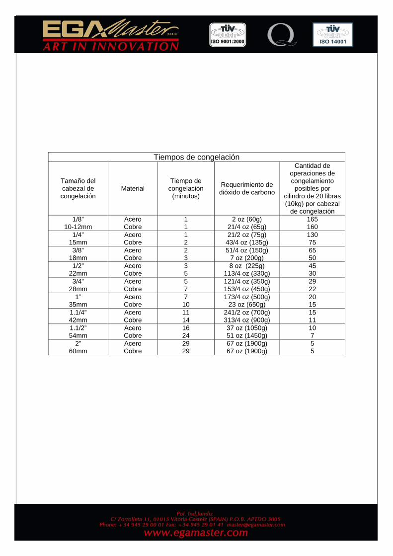
Tiempos de congelación
Tamaño del cabezal de congelación
Material Tiempo de
congelación (minutos)
Requerimiento de dióxido de carbono
Cantidad de operaciones de congelamiento posibles por
cilindro de 20 libras (10kg) por cabezal
de congelación 1/8”
10-12mm Acero Cobre
1 1
2 oz (60g) 21/4 oz (65g)
165 160
1/4” 15mm
Acero Cobre
1 2
21/2 oz (75g) 43/4 oz (135g)
130 75
3/8” 18mm
Acero Cobre
2 3
51/4 oz (150g) 7 oz (200g)
65 50
1/2” 22mm
Acero Cobre
3 5
8 oz (225g) 113/4 oz (330g)
45 30
3/4” 28mm
Acero Cobre
5 7
121/4 oz (350g) 153/4 oz (450g)
29 22
1” 35mm
Acero Cobre
7 10
173/4 oz (500g) 23 oz (650g)
20 15
1.1/4” 42mm
Acero Cobre
11 14
241/2 oz (700g) 313/4 oz (900g)
15 11
1.1/2” 54mm
Acero Cobre
16 24
37 oz (1050g) 51 oz (1450g)
10 7
2” 60mm
Acero Cobre
29 29
67 oz (1900g) 67 oz (1900g)
5 5
• TECHNICAL SPECIFICATIONS
.::Capacity: It freezes all kind of liquids types of liquids, even at high pressure, inside steel, copper, cast iron, lead, aluminum and plastic pipes .::Pipe diameters to freeze: EUR
-Steel: from 1/8” to 2” -Copper: from 10 mm to 60 mm USA -Steel: from 1/8” to 2” -Copper: from 1/4” to 2”
.::Total weight: 5Kg.
• EQUIPMENT
- Pipe freezer - 2 spiral hoses - 1 connection fitting for the hoses (T distributor) - 1 shut-off cap - 1 ball tip screwdriver (4 mm) - 2 freeze head of each size depending of the selected equipment (EUR or USA)
• GUARANTEE
Egamaster guarantees to the machine owner 12 months against any manifacture defect.
This guaranteee do not cover the parts wich are consumables. • NOTE
To apply the guarantee its necesary to send the “GUARANTEE CERTIFICATE” duly filled within one week after purchased the machine to Egamaster.
• PIPE FREEZER This pipe freezer kit can be used to freeze all types of liquids, even at high pressure, inside steel, copper, cast iron, lead, aluminum and plastic pipes in sizes ranging from 1/8” to 2” (10-60 mm). It uses commercially available carbon dioxide (CO2).
The pipe freezer kit is designed to give the user years of trouble-free, profitable service.
However, no tool is better than its operator. It´s therefore suggested the user read these instructions through carefully before using this machine on the job. This will enable the user to operate the pipe freezer kit more efficiently and more profitable. Failure to follow these instructions may cause personal injury to operator or damage to equipment. In short, these compact, simple operation and high eficiency machines have been widely applied in installing and building industries for professional repair and maintenance operations. • BASIC SAFETY INSTRUCTIONS
1) Only use the pipe freezer kit for the purpose for which it was intended, with due attention to the general safety and accident prevention
2) Keep the work area clean. Clutter can be dangerous 3) Avoid dangerous flammable liquids or gases 4) Provide adequate lighting at the workplace 5) Wear suitable work clothes, keep long hair clear, take offf jewelry and similar items 6) Use personal safety equipment (e.g. safety glasses, rubber gloves) 7) Clamp the workpiece securely, do not hold by hand 8) Check the unit occasionally for damage, and to see that it is operating correctly 9) Replace worn part as early as possible 10) Only use genuine spare parts and accessories, for personal safety reasons, to ensure
correct operation of the pipe freezer kit, and to preserve the vasis for the warrranty claim 11) All repair work must be performed only by an authorized repair facility 12) Any unauthorized modifications of the pipe freezer kit are prohibited for safety reasons
and will void the warranty
• SPECIFIC SAFETY INSTRUCTIONS
1) Carbon dioxide must be drawn from the cylinder in a liquid state in order to produce dry ice. For this reason, only cylinders equipped with a dip tube may be used
2) Do not connect a pressure reducer to the cylinder 3) Keep the cylinder in an upright position and secure it to prevent it from falling over 4) The carbon dioxide cylinder must not be emptied completely 5) Do not interfere with nozzles, freeze heads or valves, including cylinder valves 6) Work only in a well ventilated area. Carbon dioxide is non-toxic and non-flammable
but it is heavier than air and can therefore collect at ground level and displace the air if ventilation is inadequate, giving rise to the danger of suffocation
7) Wear eye protection or goggles 8) Wear gloves 9) Do not work with an open flame within 2 ft. (50 cm) of the freezing point 10) Never hit a chilled freeze head with a hammer or other tool. A sharp blow will cause it to
fracture 11) Keep other people, particularly children, well away. Dry ice causes burns if it comes into
contact with the skin. Once work is complete, any remaining dry ice in the freeze heads must be carefully disposed of or placed in a covered refuse container
12) Observe the safety instructions provided by the carbon dioxide supply company
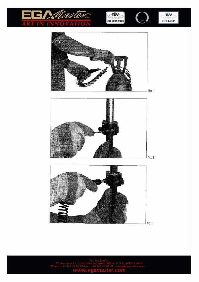
• PREPARATION FOR USE
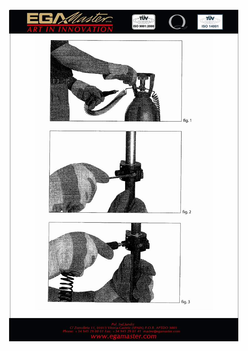
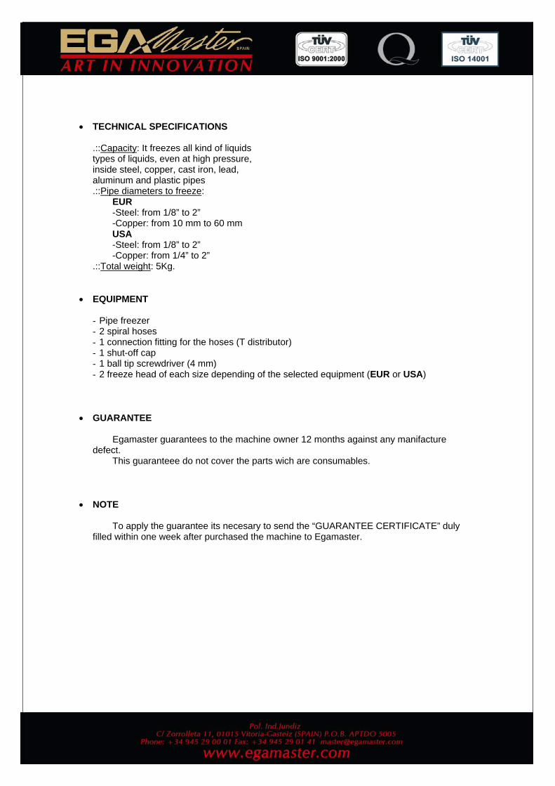
1) Remove the seal from the carbon dioxide cylinder 2) Screw connector with T-distributor on to cylinder (right-hand thread) 3) Screw spiral hoses on to the T-distributor (Fig. 1) Note: If only one spiral hose and freeze head is needed, use shut-off cap to close half of the T-distributor. 4) Choose freeze heads which correspond to the size of the pipe to be frozen. 5) Place the freeze heads on the pipe and secure by tightening the knobs evenly, using ball
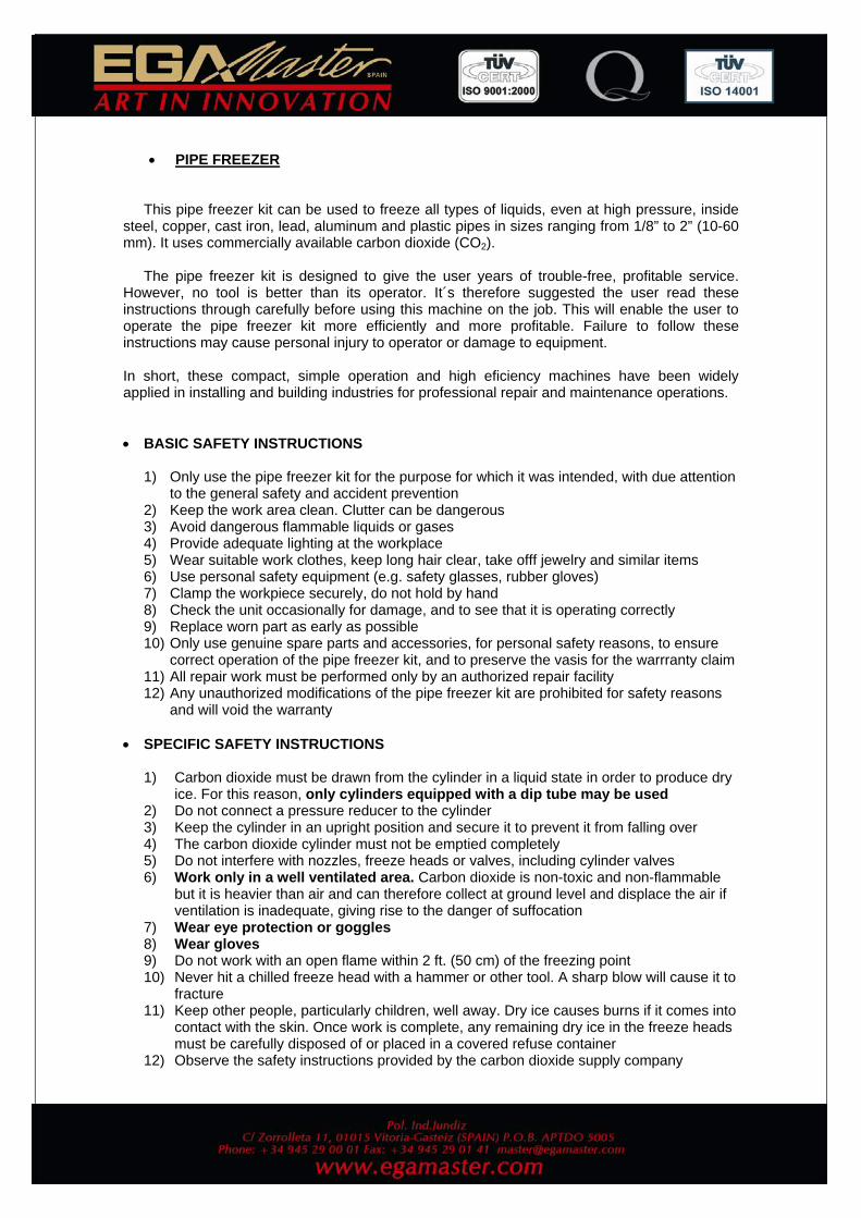
tip screwdriver provided, to give a firm but not overtight hold (Fig. 2) Warning: It is not always necessary for freeze head to clamp completely together. Once freeze head is secured tightly around the pipe, stop tightening. Over tightening can cause stress fractures of freeze head. 6) Push each injector into the bore of the freeze head until it is completely inserted and
resting against the stop, then turn clockwise one quarter turn to lock in place (Fig. 3) 7) The freeze heads should be positioned at least 40” (1m) apart from each other
• OPERATION The pipe freezer kit uses commercially available carbon dioxide (CO2). The user can purchase cylinders through him local welding supply house. Though any size cylinder can ve used, it is recommended that users purchase the largest cylinder size possible. Note: the CO2 tank must have a dip tube. The dip tube allows liquid rather than gas to flow through the spiral hoses where it will expand to form dry-ice inside the freeze heads. The ice pack which forms in the pipe is capable of withstanding a pressure of approximately 7000 psi (500 bar), As the liquid freezes, a layer of frost will develop on the surface of the pipe. 1) The liquid in the pipe can only be frozen when it is no longer flowing. All pumps must
therefore be stopped and no liquid allowed to escape from the pipe. Allow water to cool to room temperature before freezing.
2) Fully open the cylinder valve. The amount of carbon dioxide required is controlled automatically. The liquid carbon dioxide expands in the injector and forms dry ice inside the freeze head with a temperature of -110Fº (-79ºC) and freezes the liquid within the pipe.
Note: CO2 sputtering from the freeze heads during operation is normal 3) After a brief period, frost will form on the pipe in the pipe in the vicinity of the freeze
heads (see table). If frost does not form in accordance with time given in the table, then this indicates that the liquid within the pipe is still flowing or the water is too warm. (Check that all pumps have been switched off and prevent any removal or outflow of liquid).
4) While work is in progress, the flow of carbon dioxide refrigerant must be maintained. To ensure a sufficient supply of refrigerant is available, a stand-by cylinder is suggested. The only way to determine the amount of remaining carbon dioxide is to weigh the cylinder. If it is necessary to change the cylinder during work, it is essential that this procedure should be complete within 7 minutes to prevent the ice pack from melting.
5) Once work is complete, close the cylinder valve and wait until the pressure in the spiral hoses has returned to normal before removing them from value. Once the ice pack has completely melted, carefully unscrew and remove the injector at the end of the spiral hoses from the freeze head, then remove the freeze head from the pipe.
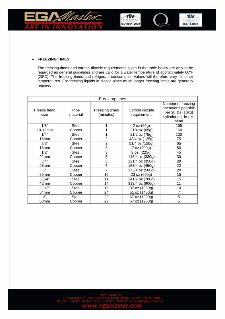
• FREEZING TIMES
The freezing times and carbon dioxide requirements given in the table below are only to be regarded as general guidelines and are valid for a water temperature of approximately 68ºF (20ºC). The freezing times and refrigerant consumption values will therefore vary for other temperatures. For freezing liquids in plastic pipes much longer freezing times are generally required.
Freezing times
Freeze head size
Pipe material
Freezing times (minutes)
Carbon dioxide requirement
Number of freezing operations possible
per 20 lbs (10kg) cylinder per freeze
head 1/8”
10-12mm Steel
Copper 1 1
2 oz (60g) 21/4 oz (65g)
165 160
1/4” 15mm
Steel Copper
1 2
21/2 oz (75g) 43/4 oz (135g)
130 75
3/8” 18mm
Steel Copper
2 3
51/4 oz (150g) 7 oz (200g)
65 50
1/2” 22mm
Steel Copper
3 5
8 oz (225g) 113/4 oz (330g)
45 30
3/4” 28mm
Steel Copper
5 7
121/4 oz (350g) 153/4 oz (450g)
29 22
1” 35mm
Steel Copper
7 10
173/4 oz (500g) 23 oz (650g)
20 15
1.1/4” 42mm
Steel Copper
11 14
241/2 oz (700g) 313/4 oz (900g)
15 11
1.1/2” 54mm
Steel Copper
16 24
37 oz (1050g) 51 oz (1450g)
10 7
2” 60mm
Steel Copper
29 29
67 oz (1900g) 67 oz (1900g)
5 5
SPAIN
- ARTICULO:.....................................................................................................
- Nº DE SERIE:..............................
- DISTRIBUIDOR:..............................................................................................
- PAIS:........................................... TELEFONO:......................................
- FECHA DE VENTA:......................................
- NOMBRE DEL COMPRADOR:.......................................................................
- TELEFONO DEL COMPRADOR:...................................
EGA MASTER GARANTIZA AL COMPRADOR DE ESTA MAQUINA LA GARANTIA TOTAL(DURANTE 12 MESES), DE LAS PIEZAS CON DEFECTOS DE FABRICACION.ESTA GARANTIA NO CUBRE AQUELLAS PIEZAS QUE POR SU USO NORMAL TIENEN UN DESGASTE.
PARA OBTENER LA VALIDEZ DE LA GARANTIA , ES ABSOLUTAMENTE IMPRESCINDIBLE QUE COMPLETE Y REMITA ESTE DOCUMENTO A EGA MASTER , DENTRO DE LOS SIETE DIAS A PARTIR DE LA FECHA DE COMPRA.
(EJEMPLAR PARA EGA MASTER)
CERTIFICADO DE GARANTIA
SELLO DEL DISTRIBUIDOR
- ARTICULO:.....................................................................................................
- Nº DE SERIE:..............................
- DISTRIBUIDOR:..............................................................................................
- PAIS:........................................... TELEFONO:......................................
- FECHA DE VENTA:......................................
- NOMBRE DEL COMPRADOR:.......................................................................
- TELEFONO DEL COMPRADOR:...................................
EGA MASTER GARANTIZA AL COMPRADOR DE ESTA MAQUINA LA GARANTIA TOTAL(DURANTE 12 MESES), DE LAS PIEZAS CON DEFECTOS DE FABRICACION.ESTA GARANTIA NO CUBRE AQUELLAS PIEZAS QUE POR SU USO NORMAL TIENEN UN DESGASTE.
PARA OBTENER LA VALIDEZ DE LA GARANTIA , ES ABSOLUTAMENTE IMPRESCINDIBLE QUE COMPLETE Y REMITA ESTE DOCUMENTO A EGA MASTER , DENTRO DE LOS SIETE DIAS A PARTIR DE LA FECHA DE COMPRA.
(EJEMPLAR PARA EL CLIENTE)
CERTIFICADO DE GARANTIA
SELLO DEL DISTRIBUIDOR
............................................................................................................................................................................................................................................................................................................
SPAIN
............................................................................................................................................................................................................................................................................................................
- ITEM:..............................................................................................................
- SERIE Nº:..........................................
- DISTRIBUTOR:...............................................................................................
- COUNTRY:......................................... PHONE:.......................................
- SALE DATE:.......................................
- BUYER NAME:................................................................................................
- BUYER PHONE:.................................
EGA MASTER GUARANTEES TO THE BUYER OF THIS MACHINE THE TOTAL WARRANTY(DURING 12 MONTHS), OF THE PIECES WITH MANUFACTURING FAULTS.THIS GUARANTEE DOES NOT COVER THOSE PIECES WORN OUT DUE TO A NORMAL USE.
IN ORDER TO OBTAIN THE VALIDITY OF THIS WARRANTY , IT IS ABSOLUTELY NECESSARY TO FULFILL THIS DOCUMENTAND RESEND IT TO EGA MASTER WITHIN 7 DAYS FROM SALE DATE.
(COPY FOR EGA MASTER)
GUARANTEE
CERTIFICATE
DISTRIBUTOR STAMP
SPAIN
- ITEM:..............................................................................................................
- SERIE Nº:..........................................
- DISTRIBUTOR:...............................................................................................
- COUNTRY:......................................... PHONE:.......................................
- SALE DATE:.......................................
- BUYER NAME:................................................................................................
- BUYER PHONE:.................................
EGA MASTER GUARANTEES TO THE BUYER OF THIS MACHINE THE TOTAL WARRANTY(DURING 12 MONTHS), OF THE PIECES WITH MANUFACTURING FAULTS.THIS GUARANTEE DOES NOT COVER THOSE PIECES WORN OUT DUE TO A NORMAL USE.
IN ORDER TO OBTAIN THE VALIDITY OF THIS WARRANTY , IT IS ABSOLUTELY NECESSARY TO FULFILL THIS DOCUMENTAND RESEND IT TO EGA MASTER WITHIN 7 DAYS FROM SALE DATE.
(COPY FOR THE CUSTOMER)
GUARANTEE
CERTIFICATE
DISTRIBUTOR STAMP
SPAIN


![Programme tubes - Van Leeuwen Pipe and Tube Group...2012 - 2013 TIQUE 2012 - 2013 BR.PNEU. 05/12 IMPRIMERIE GABEL [62594] 02 32 82 39 39 BENTELER Distribution France 15, route de Merville](https://img.pdfslide.fr/doc/110x75/610904bf0b918214f12162f5/programme-tubes-van-leeuwen-pipe-and-tube-group-2012-2013-tique-2012-2013.jpg)