Embed Size (px)
Citation preview
C. R. Mecanique 338 (2010) 615–626
Contents lists available at ScienceDirect
Comptes Rendus Mecanique
www.sciencedirect.com
Micromechanics of granular materials
Modelling of volume change in granular materials in relationto their internal state
Modélisation des variations volumiques dans les matériaux granulaires prenant encompte leur état interne
Eric Vincens ∗, Yuhanis Yunus, Bernard Cambou
Université de Lyon, LTDS, UMR CNRS 5513, École centrale de Lyon, 36, avenue Guy-de-Collongue, 69134 Écully cedex, France
a r t i c l e i n f o a b s t r a c t
Article history:Available online 20 October 2010
Keywords:Granular mediaDEMAnisotropyCharacteristic stateCycleHardening
Mots-clés :Milieux granulairesMEDAnisotropieÉtat caractéristiqueCycleÉcrouissage
Numerical simulations on samples composed of rigid spheres have been performed tostudy the behaviour of granular materials under complex stress paths involving peculiartriaxial monotonous stress paths and two-way cycling loading paths. These simulationsusing the Discrete Element Method (DEM), pointed out the concomitant role played by thevoid ratio and the anisotropy of fabric in the behaviour of these samples. Thus, the voidratio and the anisotropy of fabric have been chosen as internal variables for the descriptionof the internal state of the material. An elastic-plastic model for soils, CJS, has been usedto study the evolution of the material at the global scale. This work shows the complexpath followed by some variables or key parameters involved in this model throughoutsimulations. Moreover, the parameters that are usually taken as constants in the CJS modeldefinitely need to evolve with respect to the two internal variables in order to provide aprecise prediction of the behaviour of granular materials throughout complex loadings.
© 2010 Académie des sciences. Published by Elsevier Masson SAS. All rights reserved.
r é s u m é
Des essais numériques ont été réalisés sur des échantillons composés de sphères rigidespour étudier le comportement des matériaux granulaires sur des chemins de chargementcomplexes, impliquant des chemins triaxiaux monotones ou cycliques alternés. Cessimulations, qui utilisent la Méthode aux Eléments Discrets (MED), mettent en relief le rôleconcomitant de l’indice des vides et de l’anisotropie de structure dans le comportement deces échantillons. Aussi, l’indice des vides et l’anisotropie de structure ont-ils été choisiscomme variables pour décrire le comportement de l’état interne du matériau. Par la suite,un modèle élastoplastique de sols, CJS, a été utilisé pour étudier l’évolution du matériau àl’échelle de l’échantillon. Ce travail montre le chemin complexe suivi par certaines variablesou paramètres de modèle impliqués dans CJS au cours de ces simulations. Les simulationsont établi que ces paramètres de modèle, généralement des constantes dans CJS, doiventêtre modifiés selon la valeur des deux variables internes identifiées afin d’obtenir unedescription plus fine du comportement des matériaux granulaires sur des chemins decontraintes complexes.
© 2010 Académie des sciences. Published by Elsevier Masson SAS. All rights reserved.
* Corresponding author.E-mail address: [email protected] (E. Vincens).
1631-0721/$ – see front matter © 2010 Académie des sciences. Published by Elsevier Masson SAS. All rights reserved.doi:10.1016/j.crme.2010.10.002
616 E. Vincens et al. / C. R. Mecanique 338 (2010) 615–626
1. Introduction
So far, constitutive modelling of granular materials remains an open problem. Recently, even if compact and efficientphenomenological models were proposed to model the behaviour of soils [1–4] under monotonous loadings, accurate fore-casts for granular soils submitted to complex loading paths are difficult to obtain. These difficulties arise from the lack ofprecise information about the evolution of the internal structure of granular soils. To overcome these difficulties, discreteelement modelling (DEM) of granular materials can be very helpful. Indeed this method allows having access to informationat both the local and sample scale while the conditions of the tests are precisely controlled. First, the DEM has been used asa substitute to experimental tests and as a convenient tool to analyse the global behaviour of granular materials in relationto different loading conditions or physical properties for the studied samples ([5–10], among others). Other authors havealso used the DEM to reassess the general framework of elastoplasticity for granular material [11–13] and finally othershave used this method to study the evolution of physical internal local variables all along different loading paths able tohelp to the improvement of constitutive modelling for soils [14–19].
This study is motivated by the latter aspect and DEM simulations of triaxial tests of different kinds were performedby Yunus [18] to investigate the evolution of the internal state of samples composed of polydisperse spheres throughoutmonotonous and cyclic loading paths. Different tests, involving different densities and different states of anisotropy, showedthe dependency of classical reference states with the density and the anisotropy of fabric (orientation of normals at con-tact) [19]. These reference states are the state of maximum shear resistance and the characteristic state, transitory statebetween volumetric contractive deformations to dilative volumetric deformations for the granular material when shearingtakes place. Thus, these two variables, void ratio and anisotropy of fabric, seem to be relevant to reflect the internal state ofthe material when loading [19].
The goal of this article is to show how some variables or parameters involved in the phenomenological model CJS [20,21]are related to the evolution of the two considered internal variables. This aspect was not addressed in previous works andtypically shows the benefit of the approach to improve the forecast of constitutive models for soils. In particular, it tends todemonstrate that the parameters of constitutive models for soils must not be kept constant to provide a precise forecast ofgranular samples’ behaviour. They must depend both on the void ratio and on the anisotropy of fabric.
First, the context of the simulations and some fundamental results obtained for the simulations performed from isotropicor anisotropic states will be recalled [19]. More precisely, we present the evolution of quantities measured at the samplescale throughout the performed triaxial simulations in relation with the internal state of the material. Secondly, the mainequations of the constitutive model for soils, CJS, in relation with the studied variables or the model parameters are pre-sented. Finally, equations relating these model parameters to both void ratio and anisotropy of fabric are presented and aforecast of the characteristic state using these models under a complex loading is compared to the one directly identifiedthroughout numerical simulations.
2. Granular materials and construction of samples
The DEM simulations have been performed using PFC3D software [22]. In this code, rigid spherical bodies with de-formable contacts can be modelled. The law that rules the contact between two bodies is of Coulomb type and involvesboth a normal and a tangential stiffness (kn and ks respectively). It also requires the definition of a friction ratio f . Furtherdissipation in the system is included by means of a local non-viscous damping (also called Cundall’s damping) α defined atthe centre of each particle and proportional to acceleration forces.
The simulated material is composed of 10,000 spherical particles with diameters ranging from 3 cm to 6 cm. The pro-cedure used for the sample construction has been accurately described in [19]. Three samples with different densities havebeen obtained using three different values for the friction ratio: 0.7, 0.4 and 0 for the densest sample. Hereafter, they willbe denoted L50, M50 and D50. These friction ratios are imposed throughout the generation stage of the samples but areset to 0.7 throughout the simulated triaxial tests. Table 1 gives the values of all mechanical parameters considered in thenumerical simulations.
Table 1Mechanical properties of particles and walls.
Body Mechanical properties Values
Particles Normal rigidity 1.0e7 (N/m2)Tangential rigidity 1.0e7 (N/m2)Friction ratio 0.70Damping coefficient 0.25
Walls Normal rigidity 1.0e7 (N/m2)Tangential rigidity 1.0e7 (N/m2)Friction ratio 0.0
E. Vincens et al. / C. R. Mecanique 338 (2010) 615–626 617
3. Numerical simulations
In this section we present the global trends obtained for some reference states such as the critical state, the stateat maximum shear resistance and the characteristical state throughout simulations of monotonous triaxial tests. Thesesimulations are performed from both isotropic and anisotropic initial states and involve samples having different initialdensities.
3.1. Variables considered to characterise the internal state
Two variables have been considered to characterise the internal state: the void ratio e and a measure of the anisotropyof fabric, say the anisotropy of the orientation of normals at contacts. The tensor A associated to this anisotropy is derivedfrom the fourth rank tensor defining the tensor of fabric H which is defined by [23]:
Hijkl = 〈nin jnknl〉 (1)
where 〈 〉 denotes the average over all the contacts. More details about the use of such fourth tensor and its relationshipwith the corresponding second order tensor of normals at contacts can be found in [18] or [24]. Then a tensor defining theanisotropy of fabric is defined as:
Aijkl = Hijkl − 1
3tr(Hijkl)δi jkl (2)
Due to the symmetry of the loading (triaxial tests) and for the sake of simplicity, the component A1111 will be taken asa measure of the anisotropy within the sample. It is clear that, for the kind of loading analysed in this paper, a secondrank tensor would have given the same information. The fourth rank tensor has been chosen because it gives more accurateinformation in case of complex loadings [18,24] which will be considered in future studies.
3.2. Monotonous loadings from an isotropic initial state
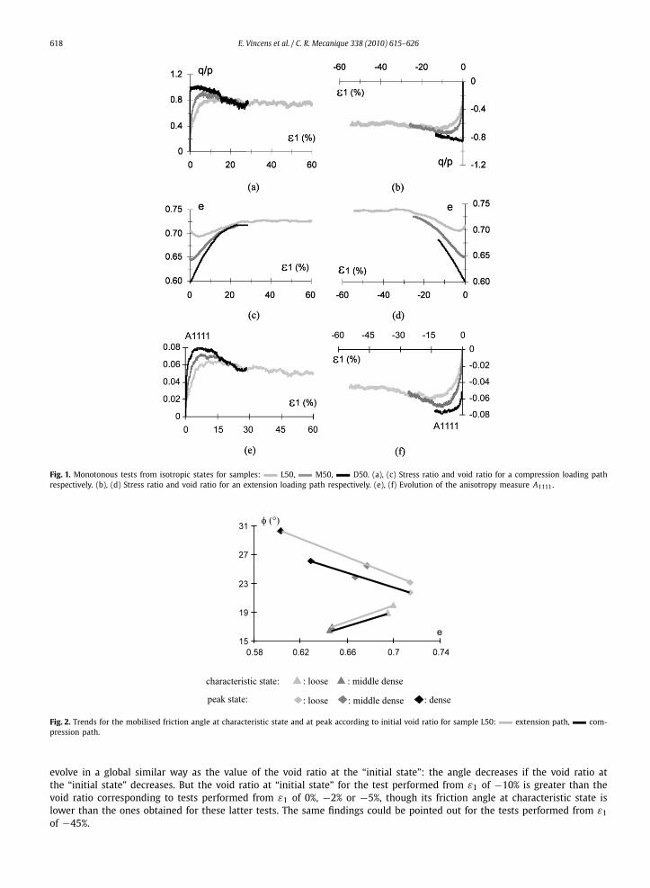
Different triaxial tests have been performed on isotropically placed materials considering different initial densities and aconfining stress of 50 kPa. Some main information obtained throughout the different simulations is drawn in Figs. 1(a), (c),for a compression stress path, and in Figs. 1(b), (d) for an extension path. In Fig. 1, the stress ratio q/p is the ratio betweenthe second invariant of the stress tensor and the mean pressure. More complete results can be obtained in [19].
All the curves show that, for very large strains (axial strain larger than 30%), the sample reaches a unique state irrespec-tive of the initial properties. This state corresponds to the well known “critical state” which is characterised by a criticalstress ratio (q/p), a critical void ratio for a given confining pressure [25–27] and a critical anisotropy. One can note thatthe internal friction angle at the critical state obtained throughout a compression test and an extension test is different.This result has previously been well established from experimental results [28]. This discrepancy is also noticeable for thecritical void ratio and the critical anisotropy obtained from a compression test and an extension test.
Fig. 2 shows the trends for the mobilised friction angle at maximum shear resistance state (peak state) and characteristicstate. When increasing the density of the material, the internal friction angle at maximum shear resistance (peak) increasesand the internal friction angle at characteristic state decreases. We recall that the characteristic state corresponds to atransitory state where the volumetric deformations pass from a contractive to a dilative pattern [29]. This result is inagreement with experimental results [30–32] and simulations performed on two-dimensional polygonal materials [33]. Itimplies that the dilative domain increases when the material is getting denser.
3.3. Monotonous loadings performed from anisotropic states
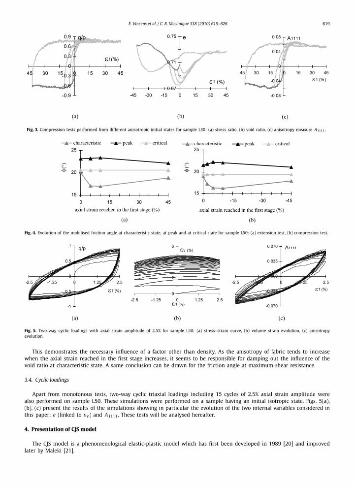
To have more insight onto the global behaviour of considered samples, further simulated triaxial tests have been per-formed on a sample exhibiting anisotropic initial states. In order to obtain an anisotropic state, sample L50 is first submittedto an extensive axial loading until reaching one of the following axial strains ε1 of −2%, −5%, −10% or −45%, giving birthto four samples exhibiting distinct “initial” states of anisotropy (dark grey path in Figs. 3(a), (b), (c)). These four samples aresubsequently and individually submitted to an axial loading in compression (stress reversal) performed up to an axial strainequal to 45% (pale grey paths in Figs. 3(a), (b), (c)).
Similar tests were performed in order to create an initial anisotropy in compression (compression test up to axial strainsε1 of 2%, 5%, 10% or 45%), and from these states, extension tests are performed. They are not shown here.
Figs. 4(a) and (b) show the different values obtained for the internal friction angle at characteristic state, at maximumshear resistance (peak) and at critical state for these two series of simulations. As expected, the critical state is foundindependent of the “initial” anisotropy indicating that history has been totally erased by the large deformations. This isnot the case for the peak state and the characteristic state. The peculiar shape of the curve related to the friction angleat characteristic state tends to show its dependency both on void ratio and anisotropy. Indeed, considering in Fig. 4(b) theresults for the compression tests shown in Figs. 3(a), (b), (c), one can note that the friction angles at the characteristic state
618 E. Vincens et al. / C. R. Mecanique 338 (2010) 615–626
Fig. 1. Monotonous tests from isotropic states for samples: L50, M50, D50. (a), (c) Stress ratio and void ratio for a compression loading pathrespectively. (b), (d) Stress ratio and void ratio for an extension loading path respectively. (e), (f) Evolution of the anisotropy measure A1111.
Fig. 2. Trends for the mobilised friction angle at characteristic state and at peak according to initial void ratio for sample L50: extension path, com-pression path.
evolve in a global similar way as the value of the void ratio at the “initial state”: the angle decreases if the void ratio atthe “initial state” decreases. But the void ratio at “initial state” for the test performed from ε1 of −10% is greater than thevoid ratio corresponding to tests performed from ε1 of 0%, −2% or −5%, though its friction angle at characteristic state islower than the ones obtained for these latter tests. The same findings could be pointed out for the tests performed from ε1of −45%.
E. Vincens et al. / C. R. Mecanique 338 (2010) 615–626 619
Fig. 3. Compression tests performed from different anisotropic initial states for sample L50: (a) stress ratio, (b) void ratio, (c) anisotropy measure A1111.
Fig. 4. Evolution of the mobilised friction angle at characteristic state, at peak and at critical state for sample L50: (a) extension test, (b) compression test.
Fig. 5. Two-way cyclic loadings with axial strain amplitude of 2.5% for sample L50: (a) stress–strain curve, (b) volume strain evolution, (c) anisotropyevolution.
This demonstrates the necessary influence of a factor other than density. As the anisotropy of fabric tends to increasewhen the axial strain reached in the first stage increases, it seems to be responsible for damping out the influence of thevoid ratio at characteristic state. A same conclusion can be drawn for the friction angle at maximum shear resistance.
3.4. Cyclic loadings
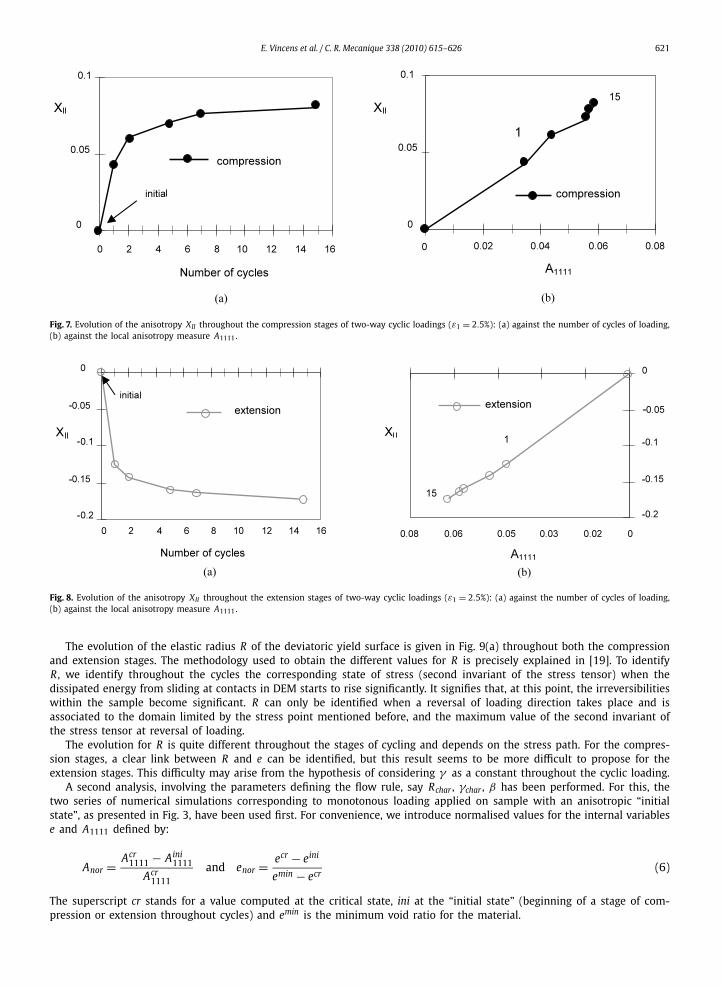
Apart from monotonous tests, two-way cyclic triaxial loadings including 15 cycles of 2.5% axial strain amplitude werealso performed on sample L50. These simulations were performed on a sample having an initial isotropic state. Figs. 5(a),(b), (c) present the results of the simulations showing in particular the evolution of the two internal variables considered inthis paper: e (linked to εv ) and A1111. These tests will be analysed hereafter.
4. Presentation of CJS model
The CJS model is a phenomenological elastic-plastic model which has first been developed in 1989 [20] and improvedlater by Maleki [21].
620 E. Vincens et al. / C. R. Mecanique 338 (2010) 615–626
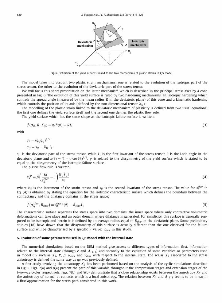
Fig. 6. Definition of the yield surfaces linked to the two mechanisms of plastic strains in CJS model.
The model takes into account two plastic strain mechanisms: one is related to the evolution of the isotropic part of thestress tensor, the other to the evolution of the deviatoric part of the stress tensor.
We will focus this short presentation on the latter mechanism which is described in the principal stress axes by a conepresented in Fig. 6. The evolution of this yield surface is ruled by two hardening mechanisms, an isotropic hardening whichcontrols the spread angle (measured by the mean radius R in the deviatoric plane) of this cone and a kinematic hardeningwhich controls the position of its axis (defined by the non-dimensional tensor Xij).
The modelling of the plastic strain linked to the deviatoric mechanism of plasticity is defined from two usual equations:the first one defines the yield surface itself and the second one defines the plastic flow rule.
The yield surface which has the same shape as the isotropic failure surface is written:
f (σi j, R, Xij) = qIIh(θ) − R I1 (3)
with
qII = (qijqi j)1/2
qij = si j − Xij .I1
si j is the deviatoric part of the stress tensor, while I1 is the first invariant of the stress tensor, θ is the Lode angle in thedeviatoric plane and h(θ) = (1 − γ cos 3θ)1/6. γ is related to the dissymmetry of the yield surface which is stated to beequal to the dissymmetry of the isotropic failure surface.
The plastic flow rule is written:
ε̇dpv = β
(sII
scharII
− 1
) |si j ε̇i j|sII
(4)
where ε̇i j is the increment of the strain tensor and sII is the second invariant of the stress tensor. The value for scharII in
Eq. (4) is obtained by stating the equation for the isotropic characteristic surface which defines the boundary between thecontractancy and the dilatancy domains in the stress space:
f(σ char
i j , Rchar) = schar
II h(θ) − Rchar I1 (5)
The characteristic surface separates the stress space into two domains, the inner space where only contractive volumetricdeformations can take place and an outer domain where dilatancy is generated. For simplicity, this surface is generally sup-posed to be isotropic and herein it is defined by an average radius equal to Rchar in the deviatoric plane. Some preliminarystudies [18] have shown that the dissymmetry of this surface is actually different than the one observed for the failuresurface and will be characterised by a specific γ value: γchar in this study.
5. Evolution of some parameters used in CJS model with the internal state
The numerical simulations based on the DEM method give access to different types of information: first, informationrelated to the internal state (through e and A1111) and secondly to the evolution of some variables or parameters usedin model CJS such as XII , R , β , Rchar and γchar with respect to the internal state. The scalar XII associated to the stressanisotropy is defined the same way as qII was previously defined.
A first study involving the anisotropy XII has been performed based on the analysis of the cyclic simulations describedin Fig. 5. Figs. 7(a) and 8(a) present the path of this variable throughout the compression stages and extension stages of thetwo-way cycles respectively. Figs. 7(b) and 8(b) demonstrate that a close relationship exists between the anisotropy XII andthe anisotropy of normal at contacts which is a local anisotropy. The relation between XII and A1111 seems to be linear ina first approximation for the stress path considered in this work.
E. Vincens et al. / C. R. Mecanique 338 (2010) 615–626 621
Fig. 7. Evolution of the anisotropy XII throughout the compression stages of two-way cyclic loadings (ε1 = 2.5%): (a) against the number of cycles of loading,(b) against the local anisotropy measure A1111.
Fig. 8. Evolution of the anisotropy XII throughout the extension stages of two-way cyclic loadings (ε1 = 2.5%): (a) against the number of cycles of loading,(b) against the local anisotropy measure A1111.
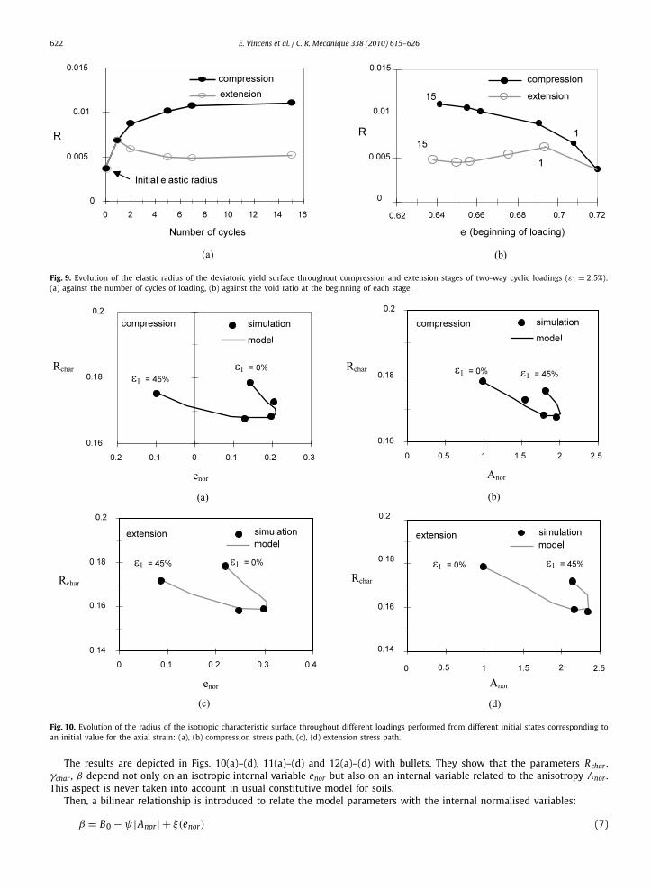
The evolution of the elastic radius R of the deviatoric yield surface is given in Fig. 9(a) throughout both the compressionand extension stages. The methodology used to obtain the different values for R is precisely explained in [19]. To identifyR , we identify throughout the cycles the corresponding state of stress (second invariant of the stress tensor) when thedissipated energy from sliding at contacts in DEM starts to rise significantly. It signifies that, at this point, the irreversibilitieswithin the sample become significant. R can only be identified when a reversal of loading direction takes place and isassociated to the domain limited by the stress point mentioned before, and the maximum value of the second invariant ofthe stress tensor at reversal of loading.
The evolution for R is quite different throughout the stages of cycling and depends on the stress path. For the compres-sion stages, a clear link between R and e can be identified, but this result seems to be more difficult to propose for theextension stages. This difficulty may arise from the hypothesis of considering γ as a constant throughout the cyclic loading.
A second analysis, involving the parameters defining the flow rule, say Rchar , γchar , β has been performed. For this, thetwo series of numerical simulations corresponding to monotonous loading applied on sample with an anisotropic “initialstate”, as presented in Fig. 3, have been used first. For convenience, we introduce normalised values for the internal variablese and A1111 defined by:
Anor = Acr1111 − Aini
1111
Acr1111
and enor = ecr − eini
emin − ecr(6)
The superscript cr stands for a value computed at the critical state, ini at the “initial state” (beginning of a stage of com-pression or extension throughout cycles) and emin is the minimum void ratio for the material.
622 E. Vincens et al. / C. R. Mecanique 338 (2010) 615–626
Fig. 9. Evolution of the elastic radius of the deviatoric yield surface throughout compression and extension stages of two-way cyclic loadings (ε1 = 2.5%):(a) against the number of cycles of loading, (b) against the void ratio at the beginning of each stage.
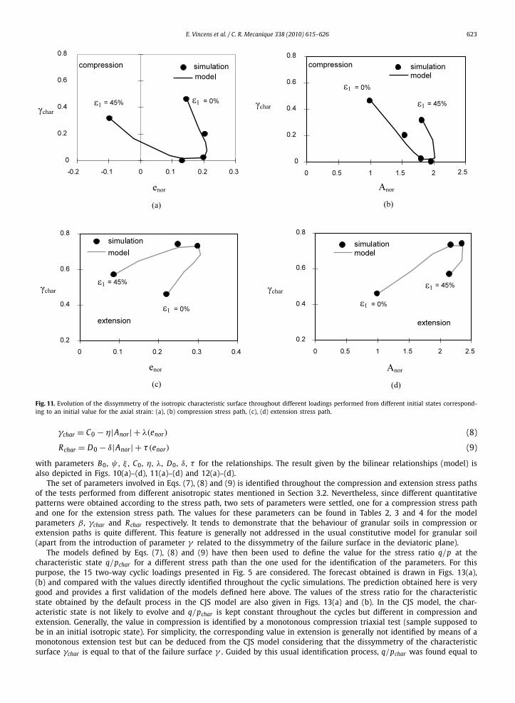
Fig. 10. Evolution of the radius of the isotropic characteristic surface throughout different loadings performed from different initial states corresponding toan initial value for the axial strain: (a), (b) compression stress path, (c), (d) extension stress path.
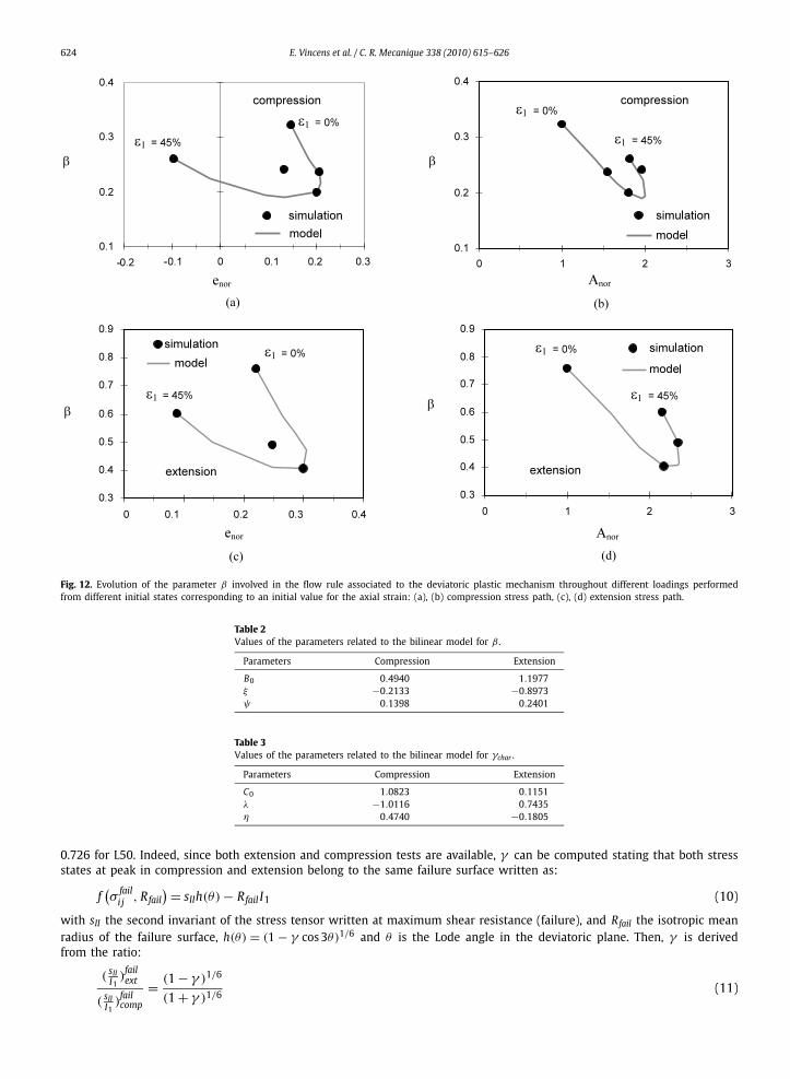
The results are depicted in Figs. 10(a)–(d), 11(a)–(d) and 12(a)–(d) with bullets. They show that the parameters Rchar ,γchar , β depend not only on an isotropic internal variable enor but also on an internal variable related to the anisotropy Anor .This aspect is never taken into account in usual constitutive model for soils.
Then, a bilinear relationship is introduced to relate the model parameters with the internal normalised variables:
β = B0 − ψ |Anor| + ξ(enor) (7)
E. Vincens et al. / C. R. Mecanique 338 (2010) 615–626 623
Fig. 11. Evolution of the dissymmetry of the isotropic characteristic surface throughout different loadings performed from different initial states correspond-ing to an initial value for the axial strain: (a), (b) compression stress path, (c), (d) extension stress path.
γchar = C0 − η|Anor| + λ(enor) (8)
Rchar = D0 − δ|Anor| + τ (enor) (9)
with parameters B0, ψ , ξ , C0, η, λ, D0, δ, τ for the relationships. The result given by the bilinear relationships (model) isalso depicted in Figs. 10(a)–(d), 11(a)–(d) and 12(a)–(d).
The set of parameters involved in Eqs. (7), (8) and (9) is identified throughout the compression and extension stress pathsof the tests performed from different anisotropic states mentioned in Section 3.2. Nevertheless, since different quantitativepatterns were obtained according to the stress path, two sets of parameters were settled, one for a compression stress pathand one for the extension stress path. The values for these parameters can be found in Tables 2, 3 and 4 for the modelparameters β , γchar and Rchar respectively. It tends to demonstrate that the behaviour of granular soils in compression orextension paths is quite different. This feature is generally not addressed in the usual constitutive model for granular soil(apart from the introduction of parameter γ related to the dissymmetry of the failure surface in the deviatoric plane).
The models defined by Eqs. (7), (8) and (9) have then been used to define the value for the stress ratio q/p at thecharacteristic state q/pchar for a different stress path than the one used for the identification of the parameters. For thispurpose, the 15 two-way cyclic loadings presented in Fig. 5 are considered. The forecast obtained is drawn in Figs. 13(a),(b) and compared with the values directly identified throughout the cyclic simulations. The prediction obtained here is verygood and provides a first validation of the models defined here above. The values of the stress ratio for the characteristicstate obtained by the default process in the CJS model are also given in Figs. 13(a) and (b). In the CJS model, the char-acteristic state is not likely to evolve and q/pchar is kept constant throughout the cycles but different in compression andextension. Generally, the value in compression is identified by a monotonous compression triaxial test (sample supposed tobe in an initial isotropic state). For simplicity, the corresponding value in extension is generally not identified by means of amonotonous extension test but can be deduced from the CJS model considering that the dissymmetry of the characteristicsurface γchar is equal to that of the failure surface γ . Guided by this usual identification process, q/pchar was found equal to
624 E. Vincens et al. / C. R. Mecanique 338 (2010) 615–626
Fig. 12. Evolution of the parameter β involved in the flow rule associated to the deviatoric plastic mechanism throughout different loadings performedfrom different initial states corresponding to an initial value for the axial strain: (a), (b) compression stress path, (c), (d) extension stress path.
Table 2Values of the parameters related to the bilinear model for β .
Parameters Compression Extension
B0 0.4940 1.1977ξ −0.2133 −0.8973ψ 0.1398 0.2401
Table 3Values of the parameters related to the bilinear model for γchar .
Parameters Compression Extension
C0 1.0823 0.1151λ −1.0116 0.7435η 0.4740 −0.1805
0.726 for L50. Indeed, since both extension and compression tests are available, γ can be computed stating that both stressstates at peak in compression and extension belong to the same failure surface written as:
f(σ
faili j , Rfail
) = sIIh(θ) − Rfail I1 (10)
with sII the second invariant of the stress tensor written at maximum shear resistance (failure), and Rfail the isotropic meanradius of the failure surface, h(θ) = (1 − γ cos 3θ)1/6 and θ is the Lode angle in the deviatoric plane. Then, γ is derivedfrom the ratio:
( sIII1
)failext
( sII )failcomp
= (1 − γ )1/6
(1 + γ )1/6(11)
I1
E. Vincens et al. / C. R. Mecanique 338 (2010) 615–626 625
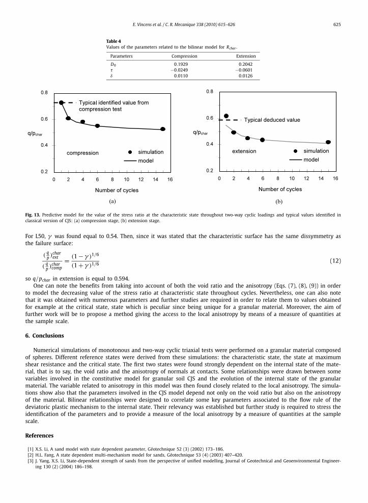
Table 4Values of the parameters related to the bilinear model for Rchar .
Parameters Compression Extension
D0 0.1929 0.2042τ −0.0249 −0.0601δ 0.0110 0.0126
Fig. 13. Predictive model for the value of the stress ratio at the characteristic state throughout two-way cyclic loadings and typical values identified inclassical version of CJS: (a) compression stage, (b) extension stage.
For L50, γ was found equal to 0.54. Then, since it was stated that the characteristic surface has the same dissymmetry asthe failure surface:
(qp )char
ext
(qp )char
comp
= (1 − γ )1/6
(1 + γ )1/6(12)
so q/pchar in extension is equal to 0.594.One can note the benefits from taking into account of both the void ratio and the anisotropy (Eqs. (7), (8), (9)) in order
to model the decreasing value of the stress ratio at characteristic state throughout cycles. Nevertheless, one can also notethat it was obtained with numerous parameters and further studies are required in order to relate them to values obtainedfor example at the critical state, state which is peculiar since being unique for a granular material. Moreover, the aim offurther work will be to propose a method giving the access to the local anisotropy by means of a measure of quantities atthe sample scale.
6. Conclusions
Numerical simulations of monotonous and two-way cyclic triaxial tests were performed on a granular material composedof spheres. Different reference states were derived from these simulations: the characteristic state, the state at maximumshear resistance and the critical state. The first two states were found strongly dependent on the internal state of the mate-rial, that is to say, the void ratio and the anisotropy of normals at contacts. Some relationships were drawn between somevariables involved in the constitutive model for granular soil CJS and the evolution of the internal state of the granularmaterial. The variable related to anisotropy in this model was then found closely related to the local anisotropy. The simula-tions show also that the parameters involved in the CJS model depend not only on the void ratio but also on the anisotropyof the material. Bilinear relationships were designed to correlate some key parameters associated to the flow rule of thedeviatoric plastic mechanism to the internal state. Their relevancy was established but further study is required to stress theidentification of the parameters and to provide a measure of the local anisotropy by a measure of quantities at the samplescale.
References
[1] X.S. Li, A sand model with state dependent parameter, Géotechnique 52 (3) (2002) 173–186.[2] H.L. Fang, A state dependent multi-mechanism model for sands, Géotechnique 53 (4) (2003) 407–420.[3] J. Yang, X.S. Li, State-dependent strength of sands from the perspective of unified modelling, Journal of Geotechnical and Geoenvironmental Engineer-
ing 130 (2) (2004) 186–198.
626 E. Vincens et al. / C. R. Mecanique 338 (2010) 615–626
[4] C.S. Chang, P.Y. Hicher, An elasto-plastic model for granular materials with microstructural consideration, International Journal of Solids and Struc-tures 42 (2005) 4258–4277.
[5] A.A. Mirghasemi, L. Rothenburg, E.L. Matyas, Numerical simulations of assemblies of two-dimensional polygon-shaped particles and effects of confiningpressure on shear strains, Soils and Foundations 37 (3) (1997) 43–52.
[6] F. Radjai, D.E. Wolf, Features of static pressure in dense granular media, Granular Matter 1 (1) (1998) 3–8.[7] C. Thornton, Numerical simulations of deviatoric shear deformation of granular media, Géotechnique 50 (1) (2000) 43–53.[8] A.A. Mirghasemi, L. Rothenburg, E.L. Matyas, Influence of particle shape on engineering properties of assemblies of two-dimensional polygon-shaped
particles, Géotechnique 52 (3) (2002) 209–217.[9] C. Nouguier-Lehon, B. Cambou, E. Vincens, Structural changes in granular materials: The case of irregular polygonal particles, International Journal of
Solids and Structures 42 (24–25) (2005) 6356–6375.[10] C. Salot, P. Gotteland, P. Villard, Influence of relative density on granular materials behavior: DEM simulations of triaxial tests, Granular Matter 11
(2009) 221–236.[11] F. Alonso-Marroquin, S. Luding, H.J. Herrmann, I. Vardoulakis, Role of anisotropy in the elastoplastic response of a polygonal packing, Physical Review
E 71 (2005) 051304.[12] C. Tamagnini, F. Calvetti, G. Viggiani, An assessment of plasticity theories for modeling the incrementally nonlinear behavior of granular soils, Journal
of Engineering Mathematics 52 (2005) 265–291.[13] F. Froiio, J.-N. Roux, An assessment of plasticity theories for modeling the incrementally non-linear behavior of granular soils, in: J. Goddard, J.T. Jenkins,
P. Giovine (Eds.), IUTAM-ISIMM Symposium on Mathematical Modelling and Physical Instances of Granular Flows, 2010, pp. 183–197.[14] L. Rothenburg, R.J. Bathurst, Analytical study of induced anisotropy in idealized granular materials, Géotechnique 39 (4) (1989) 601–614.[15] N.P. Kruyt, Contact forces in anisotropic frictional granular materials, International Journal of Solids and Structures 40 (13–14) (2003) 3537–3556.[16] M. Madadi, O. Tsoungui, M. Latzel, S. Luding, On the fabric tensor of polydisperse granular materials in 2D, International Journal of Solids and Struc-
tures 41 (2004) 2563–2580.[17] T.T. Ng, Macro- and micro-behaviors of granular materials under different sample preparation methods and stress paths, International Journal of Solids
and Structures 41 (2004) 5871–5884.[18] Y. Yunus, Modélisation discrète du comportement cyclique des matériaux granulaires (in French), PhD, Ecole Centrale de Lyon, 2008.[19] Y. Yunus, E. Vincens, B. Cambou, Numerical local analysis of relevant internal variables for constitutive modelling of granular materials, International
Journal for Numerical and Analytical Methods in Geomechanics 34 (11) (2010) 1101–1123.[20] B. Cambou, K. Jafari, A constitutive model for granular materials based on two plasticity mechanisms, in: Constitutive Equations for Granular Non-
cohesive Soils, Saada & Bianchini, Balkema, Rotterdam, 1989, pp. 149–167.[21] M. Maleki, B. Cambou, M. Farsi, P. Dubujet, An elastoplastic–viscoplastic model for soils. Numerical models in geomechanics, in: Proceedings of the 7th
International Symposium, Graz, September 1999, pp. 15–20.[22] P. Cundall, O. Strack, A discrete numerical model for granular assemblies, Géotechnique 29 (1979) 47–75.[23] B. Cambou, F. Sidoroff, Distribution orientée dans un milieu granulaire et leurs représentations, in: Journées de mécanique aléatoire appliquée à la
construction, éditions LCPC, 1986, pp. 199–204.[24] J. Rahmoun, D. Kondo, O. Millet, A 3D fourth order fabric tensor approach of anisotropy in granular media, Computational Materials Science 46 (4)
(2009) 869–880.[25] A. Casagrande, Characteristics of cohesionless soils affecting the stability of slopes and earth fills, Journal of the Boston Society of Civil Engineering
(January 1936) 13–32.[26] K.H. Roscoe, A.N. Schofield, A. Thurairajah, Yielding of clays in states wetter than critical, Géotechnique 13 (3) (1963) 211–240.[27] S.J. Poulos, The steady state of deformation, Journal of the Geoenvironmental Engineering Division ASCE 105 (2) (1981) 201–255.[28] Y.P. Vaid, E.K.F. Chung, R.H. Kuerbis, Stress path and steady state, Canadian Geotechnical Journal 27 (1990) 1–7.[29] M.P. Luong, Stress strain aspects of cohesionless soils under cyclic and transient loading, in: Proceedings of the International Symposium on Soils under
Cyclic and Transient Loading, Swansea, 1980, pp. 353–376.[30] D. Negussey, Vaid Y.P. Wijewickreme, Constant volume friction angle of granular materials, Canadian Geotechnical Journal 25 (1988) 50–55.[31] B.S. Pradhan, F. Tatsuoka, On stress–dilatancy equations of sand subjected to cyclic loading, Soils and Foundations 29 (1) (1989) 65–81.[32] H. Shahnazari, I. Towhata, Torsion shear tests on cyclic stress–dilatancy relationship of sand, Soils and Foundations 42 (1) (2002) 105–119.[33] E. Vincens, C. Nouguier-Lehon, B. Cambou, Cyclic behavior of a two dimensional polygonal-shaped material, in: 16th ALERT Geomaterials Workshop,
Aussois, October 10–12, 2005, http://alert.epfl.ch/Archive/ALERT2005/ALERTworkshop2005.html.