Embed Size (px)
Citation preview

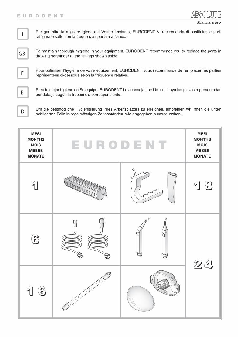
Per garantire la migliore igiene del Vostro impianto, EURODENT Vi raccomanda di sostituire le partiraffigurate sotto con la frequenza riportata a fianco.
To maintain thorough hygiene in your equipment, EURODENT recommends you to replace the parts indrawing hereunder at the timings shown aside.
Pour optimiser l’hygiène de votre équipement, EURODENT vous recommande de remplacer les partiesreprésentées ci-dessous selon la fréquence relative.
Para la mejor higiene en Su equipo, EURODENT Le aconseja que Ud. sustituya las piezas representadaspor debajo según la frecuencia correspondiente.
Um die bestmögliche Hygienisierung Ihres Arbeitsplatzes zu erreichen, empfehlen wir Ihnen die untenbebilderten Teile in regelmässigen Zeitabständen, wie angegeben auszutauschen.
MESIMONTHS
MOISMESES
MONATE
11
66
MESIMONTHS
MOISMESES
MONATE
1 81 8
I
GB
F
E
D
2 42 4
1 61 6
Manuale d’uso


10/08
COD. 653950011
TAS
TIE
RA
OP
ER
ATO
RE
OP
ER
ATO
R K
EY
BO
AR
DC
LA
VIE
R D
E L
’OP
ER
AT
EU
RT
EC
LA
DO
OP
ER
AD
OR
KO
NS
OL
E B
EH
AN
DL
ER
TAS
TIE
RA
AS
SIS
TE
NT
EA
SS
ISTA
NT
KE
YB
OA
RD
CL
AV
IER
DE
L’A
SS
ISTA
NT
ET
EC
LA
DO
AS
IST
EN
TE
KO
NS
OL
E H
EL
FE
RIN
1LP
2 3 4
27
31 29 33 24 34 35 3237
30 28 36 26 38 25
LP4
3
12
1 4 7 9 1014151918
2221
63
23
2 513 16 2017
8
1112
4139 46 4740
44 42 4345OP
LP4
3
12
O
P
MO
DE
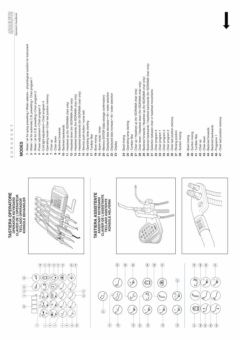
S 1
- W
ater
/ ai
r fo
r sp
ray
pres
ettin
g •
Wat
er s
elec
tor
- ph
ysio
logi
cal s
olut
ion
for
inst
rum
ent
2 -
Wat
er /
air
for
auto
mat
ic C
.B. p
rese
tting
• C
hair
prog
ram
1
3 -
Wat
er /
air
for
C.B
. pre
setti
ng •
Cha
ir pr
ogra
m 2
4 -
Pow
er a
djus
tmen
t • C
hair
prog
ram
3
5 -
Col
d lig
ht a
djus
tmen
t • C
hair
prog
ram
4
6 -
Ope
ratin
g m
ode
• C
hair
last
pos
ition
mem
ory
7 -
Cha
ir up
8 -
Cha
ir do
wn
9 -
Bac
kres
t for
war
ds10
- B
ackr
est b
ackw
ards
11 -
Hea
dres
t up
(for
ISO
RA
MA
cha
ir on
ly)
12 -
Hea
dres
t dow
n (f
or IS
OR
AM
A c
hair
only
)13
- H
eadr
est f
orw
ards
(fo
r IS
OR
AM
A c
hair
only
)14
- H
eadr
est b
ackw
ards
(fo
r IS
OR
AM
A c
hair
only
)15
- S
ervi
ce p
ush-
butto
n / n
urse
bel
l16
- O
pera
ting
lam
p st
artin
g17
- T
umbl
er fi
ller
18 -
Bow
l rin
sing
19 -
Ala
rm m
ode
/ tim
er20
- M
emor
y E
NT
ER
(da
ta s
tora
ge c
onfir
mat
ion)
21 -
Dis
play
ed d
ata
decr
ease
• A
ir / w
ater
sel
ectio
n
22
- D
ispl
ayed
dat
a in
crea
se •
Air
/ wat
er s
elec
tion
23 -
Dis
play
24 -
Bow
l rin
sing
25 -
Ope
ratin
g la
mp
star
ting
26 -
Tum
bler
fille
r27
- C
hair
up /
Hea
dres
t up
(for
ISO
RA
MA
cha
ir on
ly)
28 -
Cha
ir do
wn
/ Hea
dres
t dow
n (f
or IS
OR
AM
A c
hair
only
)29
- B
ackr
est f
orw
ards
/ H
eadr
est u
p (f
or IS
OR
AM
A c
hair
only
)30
- B
ackr
est b
ackw
ards
/ H
eadr
est b
ackw
ards
(fo
r IS
OR
AM
A c
hair
only
)31
- S
elec
tion
betw
een
chai
r or
hea
dres
t mov
emen
ts32
- C
hair
prog
ram
433
- C
hair
prog
ram
134
- C
hair
prog
ram
235
- C
hair
prog
ram
336
- C
hair
last
pos
ition
mem
ory
37 -
Rin
sing
pos
ition
38 -
Suc
tion
rinsi
ng
39 -
Bow
l rin
sing
40 -
Suc
tion
rinsi
ng41
- T
umbl
er fi
ller
42 -
Cha
ir up
43 -
Cha
ir do
wn
44 -
Bac
kres
t for
war
ds45
- B
ackr
est b
ackw
ards
46 -
Pro
gram
m 1
47 -
Cha
ir la
st p
ositi
on m
emor
y
Ope
rato
r’s h
andb
ook
FU
NZ
ION
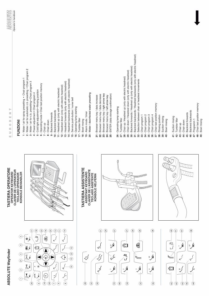
I 1
- W
ater
/ ai
r fo
r sp
ray
pres
ettin
g •
Cha
ir pr
ogra
m 1
2 -
Wat
er /
air
for
auto
mat
ic c
.b. p
rese
tting
• C
hair
prog
ram
2
3 -
Wat
er /
air
for
c.b.
pre
setti
ng •
Cha
ir pr
ogra
m 3
4
- P
ower
adj
ustm
ent •
Cha
ir pr
ogra
m 4
5 -
Col
d lig
ht a
djus
tmen
t • R
insi
ng p
ositi
on
6 -
Ope
ratin
g m
ode
• C
hair
last
pos
ition
mem
ory
7 -
Cha
ir up
8 -
Cha
ir do
wn
9 -
Bac
kres
t for
war
ds10
- B
ackr
est b
ackw
ards
11 -
Hea
dres
t up
(onl
y w
ith e
lect
ric h
eadr
est)
12 -
Hea
dres
t dow
n (o
nly
with
ele
ctric
hea
dres
t)13
- H
eadr
est f
orw
ards
(on
ly w
ith e
lect
ric h
eadr
est)
14
- H
eadr
est b
ackw
ards
(on
ly w
ith e
lect
ric h
eadr
est)
15
- S
ervi
ce p
ush-
butto
n / n
urse
bel
l16
- O
pera
ting
lam
p st
artin
g17
- T
umbl
er fi
ller
18 -
Bow
l rin
sing
19 -
Ala
rm m
ode
/ tim
er20
- W
ater
/ de
sinf
ecte
d w
ater
pre
setti
ng
21 -
Bro
wse
r m
enu
key
/ dat
a in
crea
se22
- B
row
ser
men
u ke
y / d
ata
decr
ease
23 -
Bro
wse
r m
enu
key
/ rig
ht a
rrow
key
24 -
Bro
wse
r m
enu
key
/ lef
t arr
ow k
ey25
- E
NT
ER
(da
ta s
tora
ge c
onfir
mat
ion)
26 -
Ope
ratin
g la
mp
star
ting
27 -
Tum
bler
fille
r28
- C
hair
up /
Hea
dres
t up
(onl
y w
ith e
lect
ric h
eadr
est)
29 -
Cha
ir do
wn
/ Hea
dres
t dow
n (o
nly
with
ele
ctric
hea
dres
t)
30 -
Bac
kres
t for
war
ds /
Hea
dres
t up
(onl
y w
ith e
lect
ric h
eadr
est)
31 -
Bac
kres
t bac
kwar
ds /
Hea
dres
t bac
kwar
ds (
only
with
ele
ctric
hea
dres
t)32
- S
elec
tion
betw
een
chai
r or
hea
dres
t mov
emen
ts
33 -
Cha
ir pr
ogra
m 1
34 -
Cha
ir pr
ogra
m 2
35 -
Cha
ir pr
ogra
m 3
36 -
Cha
ir pr
ogra
m 4
37 -
Cha
ir la
st p
ositi
on m
emor
y38
- R
insi
ng p
ositi
on39
- S
uctio
n rin
sing
40 -
Bow
l rin
sing
41 -
Suc
tion
rinsi
ng42
- T
umbl
er fi
ller
43 -
Cha
ir up
44 -
Cha
ir do
wn
45 -
Bac
kres
t for
war
ds46
- B
ackr
est b
ackw
ards
47 -
Pro
gram
m 1
48 -
Cha
ir la
st p
ositi
on m
emor
y49
- B
owl r
insi
ng
TAS
TIE
RA
OP
ER
ATO
RE
OP
ER
ATO
R K
EY
BO
AR
DC
LA
VIE
R D
E L
’OP
ER
AT
EU
RT
EC
LA
DO
OP
ER
AD
OR
KO
NS
OL
E B
EH
AN
DL
ER
TAS
TIE
RA
AS
SIS
TE
NT
EA
SS
ISTA
NT
KE
YB
OA
RD
CL
AV
IER
DE
L’A
SS
ISTA
NT
ET
EC
LA
DO
AS
IST
EN
TE
KO
NS
OL
E H
EL
FE
RIN
Ope
rato
r’s h
andb
ook
21
34
SP
P
LP
1LP
2 3 4SP
1 LP
213
2
1215
1022
1
6
17 23 25 1118 16 13 14
7 819 24 9
45
31 37 27 26 3829 39
28 30 33 34 35 3632 40
49 47 4841
42 43 4445 46AB
SO
LU
TE
Way
nd
er
20
1
Operator’s handbook
INDEX
1 FOREWORD ........................................................................................................................................................
2 TECHNICAL FEATURES ......................................................................................................................................
3 SWITCHING ON ....................................................................................................................................................
4 POSITIONING THE MODULE ARM ....................................................................................................................
5 ABSOLUTE ..........................................................................................................................................................
5.1 CLOCK ADJUSTMENT ..............................................................................................................................
5.2 PATIENT POSITIONING ............................................................................................................................
5.3 ALARM MODE / TIMER ..............................................................................................................................
5.4 TUMBLER FILLER ......................................................................................................................................
5.5 BOWL RINSING ..........................................................................................................................................
5.6 LAMP OPERATION .....................................................................................................................................
5.7 SERVICE PUSH BUTTON .........................................................................................................................
5.8 FOOT-CONTROL SWITCHES .....................................................................................................................
Isotron Foot-Control .......................................................................................................................................
Blue Foot Control .......................................................................................................................................
5.9 PROGRAMMABLE MODES FOR THE INSTRUMENTS ...........................................................................
5.10 MODULES ..................................................................................................................................................
Syringe module and fibre optic syringe module .........................................................................................
Turbine module and variable speed turbine module with fibre optic ..........................................................
Fibre optic micromotor module ...................................................................................................................
High torque micromotor module with fibre optic / with physiodispenser .....................................................
Induction micromotor module ......................................................................................................................
Induction micromotor module with physiodispenser ...................................................................................
Scaler module .............................................................................................................................................
Isojet powder cleaner module ....................................................................................................................
Camera module ....................................................................................................................................
Bistoury module ..........................................................................................................................................
Mini Led light cure module .........................................................................................................................
Snowhow whitening module .......................................................................................................................
5.11 ASEPSIS MODE .........................................................................................................................................
5.12 MESSAGES EXPLANATION .....................................................................................................................
5.13 PARAMETERS PRESETTING ...................................................................................................................
6 ABSOLUTE WAYFINDER ....................................................................................................................................
6.1 GENERAL DESCRIPTION OF THE DISPLAY ..........................................................................................
6.2 PATIENT POSITIONING ............................................................................................................................
6.3 ALARM .......................................................................................................................................................
6.4 TUMBLER FILLER ......................................................................................................................................
6.5 BOWL RINSING .........................................................................................................................................
6.6 LAMP OPERATION ....................................................................................................................................
6.7 SERVICE PUSH-BUTTON ..........................................................................................................................
6.8 FOOT-CONTROL SWITCHES ...................................................................................................................
Isotron Foot-Control ......................................................................................................................................
Blue Foot Control .......................................................................................................................................
6.9 STRUCTURE OF THE MAIN MENU .........................................................................................................
3
4
5
5
66
6
9
10
10
10
11
12
12
13
15
17
18
18
19
19
20
22
23
23
24
24
25
26
27
27
29
3030
31
35
36
36
36
37
38
38
39
42
2
Operator’s handbook
6.10 PROGRAMMABLE INSTRUMENT FEATURES ........................................................................................
6.11 MODULES .................................................................................................................................................
47
52
53
54
55
56
57
60
61
62
63
63
64
65
66
66
69
7070
71
71
71
72
72
73
73
73
74
74
7576
76
77
Syringe module and fibre optic syringe module .........................................................................................
Turbine module and variable speed turbine module with fibre optic ..........................................................
Fibre optic micromotor module ..................................................................................................................
High torque micromotor module with fibre optic / with physiodispenser ....................................................
Induction micromotor module .....................................................................................................................
Induction micromotor module with physiodispenser ..................................................................................
Scaler module ............................................................................................................................................
Isojet powder cleaner module ....................................................................................................................
Camera module ....................................... ............................................................................................
Bistoury module .........................................................................................................................................
Mini Led light cure module .........................................................................................................................
Snowhow whitening module .......................................................................................................................
6.12 ASEPSIS MODE ........................................................................................................................................
6.13 MESSAGES EXPLANATION ....................................................................................................................
7 STERILIZATION METHODS AND WORKING TIMES ......................................................................................
8 MAINTENANCE ..................................................................................................................................................
MODULE-HOLDER ARM BALANCING ....................................................................................................
WATER DRAIN FROM AIR FILTER ..........................................................................................................
CLEANING OF SUCTION FILTER ..................................................................................................................
FILLING OF DETERGENT TANK ..............................................................................................................
FILLING OF MEDICAMENT TANK ............................................................................................................
FILLING OF PHYSIOLOGICAL SOLUTION ..............................................................................................
DISINFECTANT SOLUTION .....................................................................................................................
REPLACEMENT OF STERILE SOLUTION BOTTLE ...................................................................................
PARAMETERS SETTING .........................................................................................................................
BLUE FOOT CONTROL BATTERY RECHARGE .....................................................................................
SURFACE CLEANING ..............................................................................................................................
9 METASYS MST1 AMALGAM SEPARATOR .....................................................................................................
REMOVING AND CLEANING THE FILTER ..............................................................................................
REMOVING THE AMALGAM SEPARATOR VESSEL ..............................................................................
ECOLOGIC SYSTEM OF RECOVERY ......................................................................................................
3
Operator’s handbook
Dear Doctor,
the EURODENT GROUP is pleased with your choice of the ABSOLUTE equipment and proud of the favouryou grant us.
The Absolute unit has been designed according to three main principles:
ASEPSIS CONTROL, OPERATIONAL FLEXIBILITY AND COMFORT.
Surface smoothness, combined with roundish contours and lack of slits and corners, allows an easy externalcleaning and prevents from dusts and sprays deposit. Controls are made so that contact with fingers isavoided whenever possible.
All handpieces are fitted with anti-retraction valving, to prevent risks of cross-contamination.
Lightness of movement and breadth of operational displacement of the modules arm, easyness of access tothe patient for both Doctor and Assistant and, last but not least, the flexible microprocessor control of the mainactivities of the apparatus, all make of ABSOLUTE a ductile system ready to match and support the Operators’work attitudes.
The soft profile of the unit and handpieces asset, the anatomic shaping of the chair, the reassuring designof control decks, everything cooperates to frame the comfortable sensation induced into the patient, who willmore confidently relax himself so making easier the Operators’ activity.
Wa are certain that your choice will prove widely fulfilling both because of the equipment functionality andreliability and thanks to the benefits in terms of prestige as to your Patients and Collegues.
This booklet will help you to obtain the best from your ISOTRON. While reminding you that we are at yourdisposal for any information that you might require, we remain
Sincerely yours,
FOREWORD1
4
Operator’s handbook
TECHNICAL FEATURES2
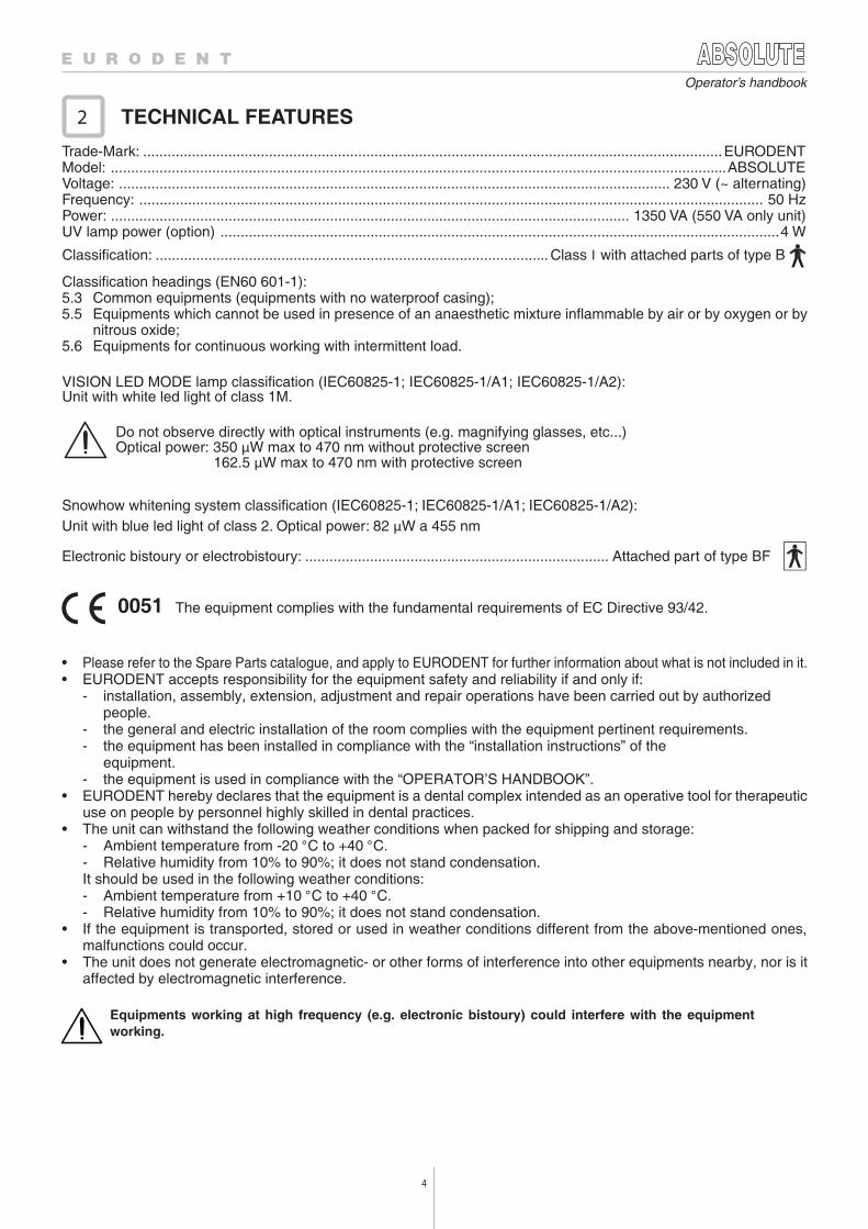
Trade-Mark: ...............................................................................................................................................EURODENTModel: ........................................................................................................................................................ABSOLUTEVoltage: ........................................................................................................................................ 230 V (~ alternating)Frequency: .......................................................................................................................................................... 50 HzPower: ................................................................................................................................ 1350 VA (550 VA only unit)UV lamp power (option) ..........................................................................................................................................4 W
Classification: ................................................................................................. Class I with attached parts of type B
Classification headings (EN60 601-1):5.3 Common equipments (equipments with no waterproof casing);5.5 Equipments which cannot be used in presence of an anaesthetic mixture inflammable by air or by oxygen or by
nitrous oxide;5.6 Equipments for continuous working with intermittent load.
VISION LED MODE lamp classification (IEC60825-1; IEC60825-1/A1; IEC60825-1/A2):Unit with white led light of class 1M.
Do not observe directly with optical instruments (e.g. magnifying glasses, etc...)Optical power: 350 μW max to 470 nm without protective screen
162.5 μW max to 470 nm with protective screen
Snowhow whitening system classification (IEC60825-1; IEC60825-1/A1; IEC60825-1/A2):Unit with blue led light of class 2. Optical power: 82 μW a 455 nm
Electronic bistoury or electrobistoury: ........................................................................... Attached part of type BF
0051 The equipment complies with the fundamental requirements of EC Directive 93/42.
• Please refer to the Spare Parts catalogue, and apply to EURODENT for further information about what is not included in it.• EURODENT accepts responsibility for the equipment safety and reliability if and only if:
- installation, assembly, extension, adjustment and repair operations have been carried out by authorizedpeople.
- the general and electric installation of the room complies with the equipment pertinent requirements.- the equipment has been installed in compliance with the “installation instructions” of the
equipment.- the equipment is used in compliance with the “OPERATOR’S HANDBOOK”.
• EURODENT hereby declares that the equipment is a dental complex intended as an operative tool for therapeuticuse on people by personnel highly skilled in dental practices.
• The unit can withstand the following weather conditions when packed for shipping and storage:- Ambient temperature from -20 °C to +40 °C.- Relative humidity from 10% to 90%; it does not stand condensation.It should be used in the following weather conditions:- Ambient temperature from +10 °C to +40 °C.- Relative humidity from 10% to 90%; it does not stand condensation.
• If the equipment is transported, stored or used in weather conditions different from the above-mentioned ones,malfunctions could occur.
• The unit does not generate electromagnetic- or other forms of interference into other equipments nearby, nor is itaffected by electromagnetic interference.
Equipments working at high frequency (e.g. electronic bistoury) could interfere with the equipmentworking.
5
Operator’s handbook
Operating instructions
Refer to instruction manual/booklet
Caution
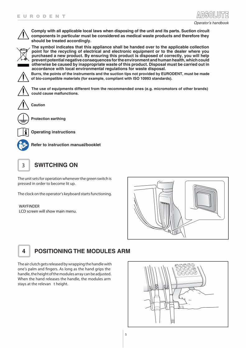
WAYFINDERLCD screen will show main menu.
LP43
SWITCHING ON3
POSITIONING THE MODULES ARM4
Comply with all applicable local laws when disposing of the unit and its parts. Suction circuitcomponents in particular must be considered as medical waste products and therefore theyshould be treated accordingly.
Burrs, the points of the instruments and the suction tips not provided by EURODENT, must be madeof bio-compatible materials (for example, compliant with ISO 10993 standards).
The use of equipments different from the recommended ones (e.g. micromotors of other brands) could cause malfunctions.
Protection earthing
The symbol indicates that this appliance shall be handed over to the applicable collectionpoint for the recycling of electrical and electronic equipment or to the dealer where youpurchased a new product. By ensuring this product is disposed of correctly, you will helpprevent potential negative consequences for the environment and human health, which couldotherwise be caused by inappropriate waste of this product. Disposal must be carried out inaccordance with local environmental regulations for waste disposal.
The unit sets for operation whenever the green switch ispressed in order to become lit up.
The clock on the operator’s keyboard starts functioning.
The air clutch gets released by wrapping the handle withone’s palm and fingers. As long as the hand grips thehandle, the height of the modules array can be adjusted.When the hand releases the handle, the modules armstays at the relevan t height.
6
Operator’s handbook
5.1
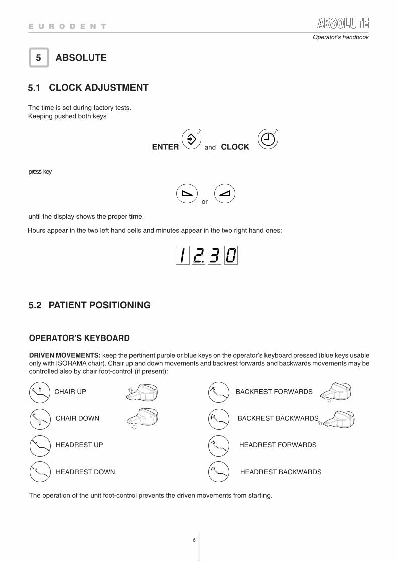
ENTER and CLOCK
press key
or
ABSOLUTE5
5.2
The time is set during factory tests.Keeping pushed both keys
until the display shows the proper time.
Hours appear in the two left hand cells and minutes appear in the two right hand ones:
CLOCK ADJUSTMENT
OPERATOR’S KEYBOARD
DRIVEN MOVEMENTS: keep the pertinent purple or blue keys on the operator’s keyboard pressed (blue keys usableonly with ISORAMA chair). Chair up and down movements and backrest forwards and backwards movements may becontrolled also by chair foot-control (if present):
BACKREST FORWARDSCHAIR UP
BACKREST BACKWARDSCHAIR DOWN
HEADREST FORWARDSHEADREST UP
HEADREST BACKWARDSHEADREST DOWN
The operation of the unit foot-control prevents the driven movements from starting.
PATIENT POSITIONING
7
Operator’s handbook
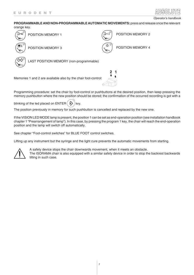
Memories 1 and 2 are available also by the chair foot-control:
PROGRAMMABLE AND NON-PROGRAMMABLE AUTOMATIC MOVEMENTS: press and release once the relevantorange key.
Programming procedure: set the chair by foot-control or pushbuttons at the desired position, then keep pressing thememory pushbutton where the new position should be stored; the confirmation of the occurred recording is got with a
blinking of the led placed on ENTER key.
The position previously in memory for such pushbutton is cancelled and replaced by the new one.
If the VISION LED MODE lamp is present, the position 1 can be set as end-operation position (see installation handbookchapter 1 “Prearrangement of lamp”). In this case, by pressing the program 1 key, the chair will reach the end-operationposition and the lamp will switch off automatically.
See chapter “Foot-control switches” for BLUE FOOT control switches.
Lifting up any instrument but the syringe and the light cure prevents the automatic movements from starting.
LAST POSITION MEMORY (non-programmable)
1 2
3 4
LP
12
A safety device stops the chair downwards movement, when it meets an obstacle.The ISORAMA chair is also equipped with a similar safety device in order to stop the backrest backwardstilting in such case.
POSITION MEMORY 1
POSITION MEMORY 3
POSITION MEMORY 2
POSITION MEMORY 4
8
Operator’s handbook
If the VISION LED MODE lamp is present, the position 1 can be set as end-operation position (see installation handbookchapter 1 “Prearrangement of lamp”). In this case, by pressing the program 1 key, the chair will reach the end-operationposition and the lamp will switch off automatically.
When key
If the backrest is already in vertical position, pressing the key the backrest returns in to the last position.
is pressed only the backrest moves, in order to reach the vertical position.
ASSISTANT’S KEYBOARD
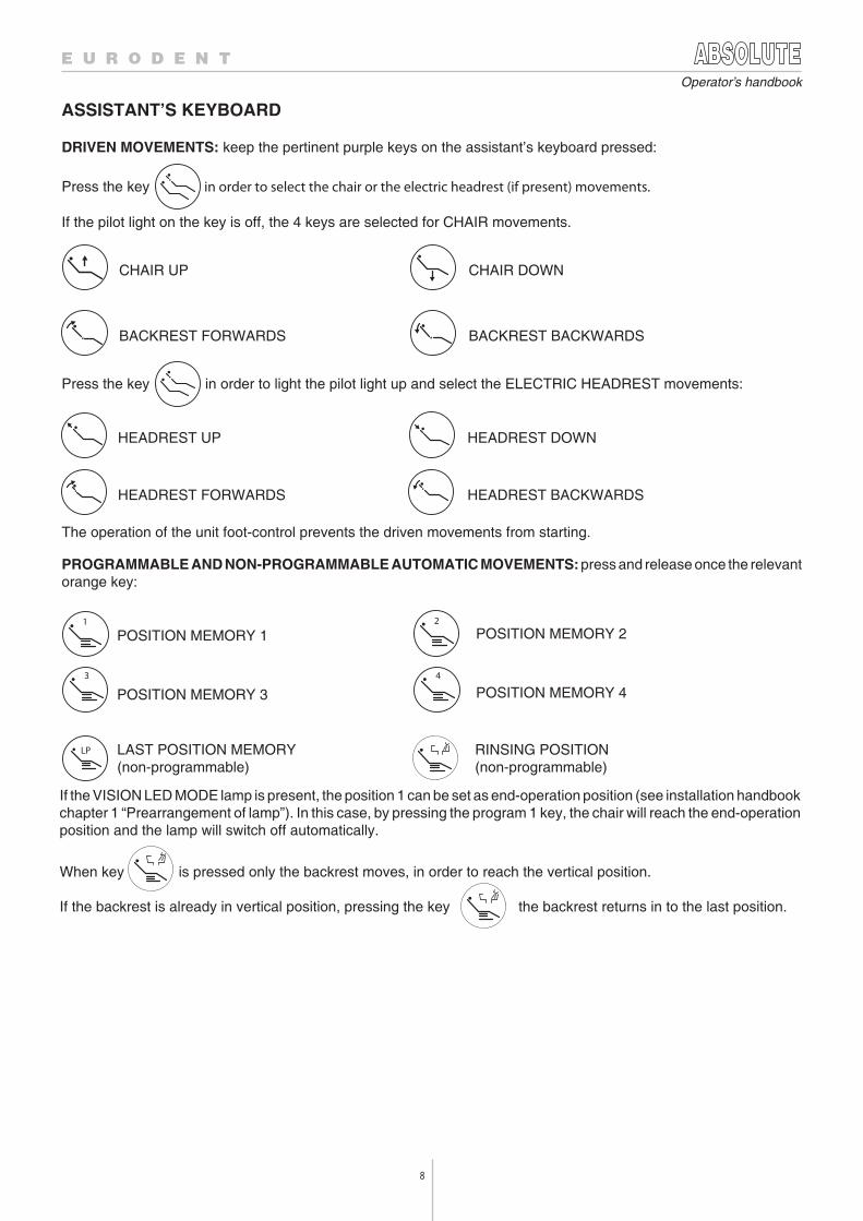
DRIVEN MOVEMENTS: keep the pertinent purple keys on the assistant’s keyboard pressed:
Press the key in order to select the chair or the electric headrest (if present) movements.
If the pilot light on the key is off, the 4 keys are selected for CHAIR movements.
The operation of the unit foot-control prevents the driven movements from starting.
PROGRAMMABLE AND NON-PROGRAMMABLE AUTOMATIC MOVEMENTS: press and release once the relevantorange key:
Press the key in order to light the pilot light up and select the ELECTRIC HEADREST movements:
CHAIR UP CHAIR DOWN
BACKREST FORWARDS BACKREST BACKWARDS
HEADREST UP HEADREST DOWN
HEADREST FORWARDS HEADREST BACKWARDS
1 2
3
LP
4
LAST POSITION MEMORY(non-programmable)
POSITION MEMORY 1
POSITION MEMORY 3
POSITION MEMORY 2
POSITION MEMORY 4
RINSING POSITION (non-programmable)
9
Operator’s handbook
5.3 ALARM MODE/TIMER
With a VISION LED MODE lamp, the light intensity will reach a lower intensity level. When the last-position memory keyor one of the programmed position key are pressed, the lamp will reach the previous light intensity level.
Lifting up any instrument but the syringe and the light cure prevents the automatic movements from starting.
OPERATOR’S KEYBOARD WITH 9 KEYS
DRIVEN CONTROLS: keep the pertinent purple keys on the operator’s keyboard pressed:
CHAIR UP CHAIR DOWN BACKREST FORWARDS BACKREST BACKWARDS
The operation of the unit foot-control prevents the driven movements from starting.
AUTOMATIC PROGRAMMABLE CONTROLS: are started pressing the orange keys.
POSITION MEMORY 1 LAST OPERATION POSITION MEMORY USED
See details about position memory 1 in the previous paragraph.Lifting up any instrument but the syringe and the light cure prevents the automatic movements from starting.
1 LP
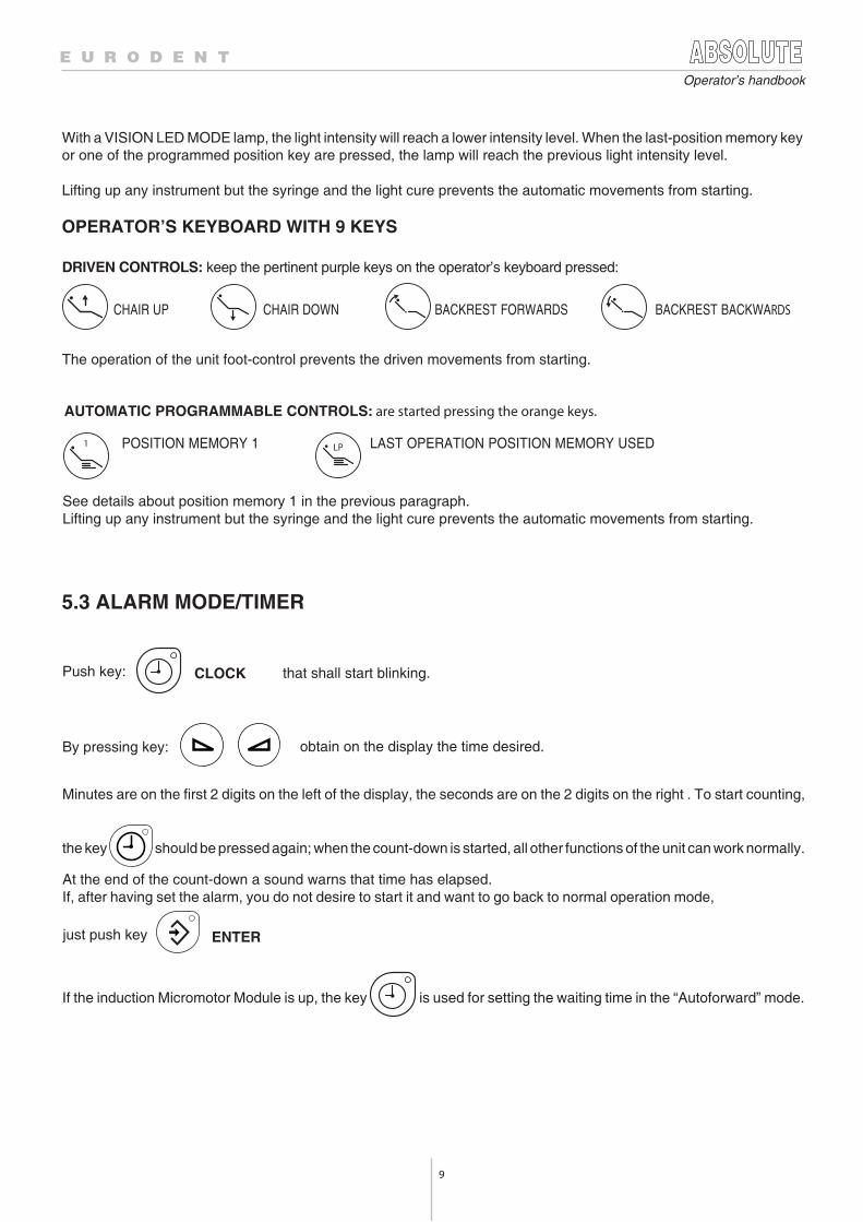
Push key: CLOCK that shall start blinking.
By pressing key: obtain on the display the time desired.
Minutes are on the first 2 digits on the left of the display, the seconds are on the 2 digits on the right . To start counting,
the key should be pressed again; when the count-down is started, all other functions of the unit can work normally.
At the end of the count-down a sound warns that time has elapsed.If, after having set the alarm, you do not desire to start it and want to go back to normal operation mode,
ENTER
If the induction Micromotor Module is up, the key is used for setting the waiting time in the “Autoforward” mode.
just push key
10
Operator’s handbook
5.4 TUMBLER FILLER
5.5 BOWL RINSING
5.6 LAMP OPERATION
It can be operated either by using the control on the suction tubings support arm or pressing the white key:
TUMBLER
or, if the handpieces lie in resting array, with the foot-control (see Chap. “Foot-control switches”) by pushingdownward the small pedal in the foot-control.
TIME ADJUSTMENT:
Push both keys TUMBLER and
ENTER
The display shall show a count-up in tenths of second;when reaching the quantity of water desired in the tumbler, release the keys.
From now until next adjustment, and whenever the key TUMBLER is activated, the tumbler filler shall supply waterfor the programmed time.
The bowl flush starts automatically following the tumbler filler stop, and stops automatically when the programmed timehas elapsed. To change the programmed time, see the section:“PARAMETERS PRESETTING”.
To start the bowl flush independently from the tumbler filling, press the white key:
BOWL
or use the control on the suction tubings support arm.
ISOLUX LAMP
The lamp can be switched on by photocell or by switch. The unit should be properly programmed just as the lampinstallation.The white key:
LAMP
switches the lamp on. The lamp can also be switched on and off from the foot-control lever, by pushing it from the properlever leftward when the instruments are in resting array.
Do not point the beam at the patient’s eyes.
11
Operator’s handbook
VISION LED MODE LAMP
The lamp has two intensity levels, each of them can be set.
Pressing the key shortly:
and
and
5.7 SERVICE PUSH-BUTTON
Do not point the beam at the patient’s eyes..
to increase it.
The lamp will be switched on at the lower level of light intensity. To increase the intensity, press again the same key.On the back side of the lamp there are two leds, a green one that indicates when it is on, that the lamp is correctly suppliedand a blue one that shows when it is on, that the lamp is at the lowest intensity level, while if the led is off, this meansthat the intensity is at the highest level.
to decrease the intensity, and the keys:
The light intensity of each level can be changed by pressing simultaneously the keys:
The white key:
SERVICE
closes any external circuit (max 24 V - 1 A) for the assistant call, door opening, and so on.
When the maximum or minimum intensity level is reached, a blue led will start blinking.When the lamp is switched off the new settings will be stored. The lamp is switched off by pressing the key for more
than 1 s:
All these functions can be activated by the no-touch sensors placed on the lamp’s head. Placing the hand in the area
where the symbol is positioned (without touching the guard) : the lamp is switched on,
the change in intensity and the switching off are obtained with the same modalities seen previously.
By placing the hand near the symbol: the light intensity will increase and reach the selected level and
in the same way, by placing the hand near the symbol: the intensity will decrease.
The above-mentioned functions of switching on, switching off and change in intensity can be activated by the foot-control, too (Chap. “Foot-control switches”). By shifting once the lever rightward for less than 1 s, the lamp will be switched on at the lowest intensity, another stroke increases the level of intensity, the switching off is obtained by shiftingthe lever rightward for more than 1 s.
12
Operator’s handbook
5.8 FOOT-CONTROL SWITCHES
ISOTRON FOOT-CONTROL
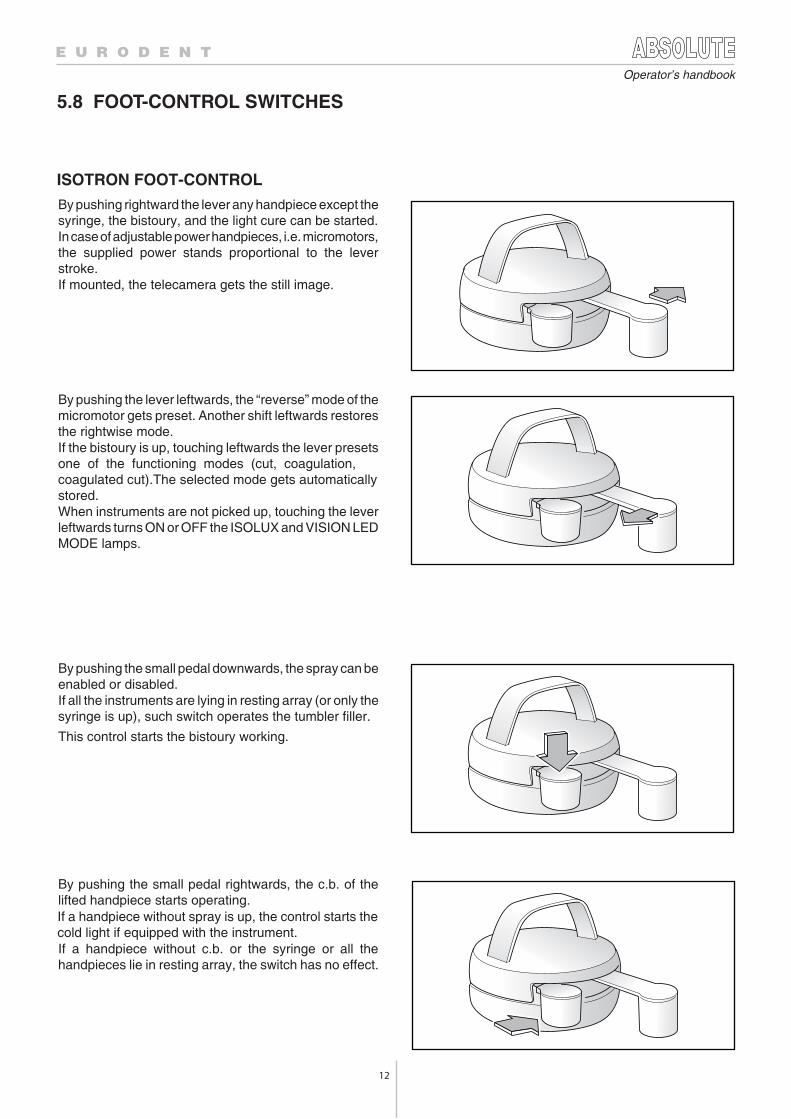
By pushing rightward the lever any handpiece except thesyringe, the bistoury, and the light cure can be started.In case of adjustable power handpieces, i.e. micromotors,the supplied power stands proportional to the leverstroke.If mounted, the telecamera gets the still image.
By pushing the small pedal downwards, the spray can beenabled or disabled.If all the instruments are lying in resting array (or only thesyringe is up), such switch operates the tumbler filler.
This control starts the bistoury working.
By pushing the lever leftwards, the “reverse” mode of themicromotor gets preset. Another shift leftwards restoresthe rightwise mode.If the bistoury is up, touching leftwards the lever presetsone of the functioning modes (cut, coagulation,coagulated cut).The selected mode gets automaticallystored.When instruments are not picked up, touching the leverleftwards turns ON or OFF the ISOLUX and VISION LEDMODE lamps.
By pushing the small pedal rightwards, the c.b. of thelifted handpiece starts operating.
If a handpiece without c.b. or the syringe or all thehandpieces lie in resting array, the switch has no effect.
If a handpiece without spray is up, the control starts thecold light if equipped with the instrument.
13
Operator’s handbook
BLUE FOOT CONTROL
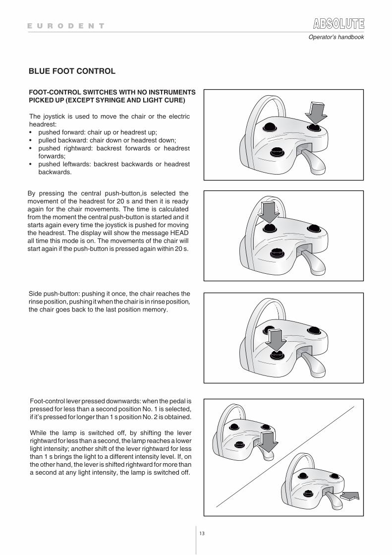
The joystick is used to move the chair or the electricheadrest:• pushed forward: chair up or headrest up;• pulled backward: chair down or headrest down;• pushed rightward: backrest forwards or headrest
forwards;• pushed leftwards: backrest backwards or headrest
backwards.
Foot-control lever pressed downwards: when the pedal ispressed for less than a second position No. 1 is selected,if it’s pressed for longer than 1 s position No. 2 is obtained.
While the lamp is switched off, by shifting the leverrightward for less than a second, the lamp reaches a lowerlight intensity; another shift of the lever rightward for lessthan 1 s brings the light to a different intensity level. If, onthe other hand, the lever is shifted rightward for more thana second at any light intensity, the lamp is switched off.
Side push-button: pushing it once, the chair reaches therinse position, pushing it when the chair is in rinse position,the chair goes back to the last position memory.
By pressing the central push-button,is selected themovement of the headrest for 20 s and then it is readyagain for the chair movements. The time is calculatedfrom the moment the central push-button is started and itstarts again every time the joystick is pushed for movingthe headrest. The display will show the message HEADall time this mode is on. The movements of the chair willstart again if the push-button is pressed again within 20 s.
FOOT-CONTROL SWITCHES WITH NO INSTRUMENTS PICKED UP (EXCEPT SYRINGE AND LIGHT CURE)
14
Operator’s handbook
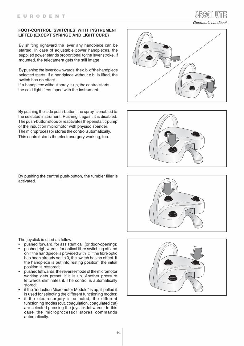
By pushing the side push-button, the spray is enabled tothe selected instrument. Pushing it again, it is disabled.The push-button stops or reactivates the peristaltic pumpof the induction micromotor with physiodispender.The microprocessor stores the control automatically.
If a handpiece without spray is up, the control starts the cold light if equipped with the instrument.
This control starts the electrosurgery working, too.
By pushing the central push-button, the tumbler filler isactivated.
The joystick is used as follow:• pushed forward, for assistant call (or door-opening);• pushed rightwards, for optical fibre switching off and
on if the handpiece is provided with it; if the fibre optichas been already set to 0, the switch has no effect. Ifthe handpiece is put into resting position, the initialposition is restored;
• pushed leftwards, the reverse mode of the micromotorworking gets preset, if it is up. Another pressureleftwards eliminates it. The control is automaticallystored;
• if the “induction Micromotor Module” is up, if pulled itis used for selecting the different functioning modes;
• if the electrosurgery is selected, the differentfunctioning modes (cut, coagulation, coagulated cut)are selected pressing the joystick leftwards. In thiscase the microprocessor stores commandsautomatically.
By shifting rightward the lever any handpiece can bestarted. In case of adjustable power handpieces, thesupplied power stands proportional to the lever stroke. Ifmounted, the telecamera gets the still image.
By pushing the lever downwards, the c.b. of the handpieceselected starts. If a handpiece without c.b. is lifted, theswitch has no effect.
FOOT-CONTROL SWITCHES WITH INSTRUMENTLIFTED (EXCEPT SYRINGE AND LIGHT CURE)
15
Operator’s handbook
5.9 PROGRAMMABLE MODES FOR THE INSTRUMENTS
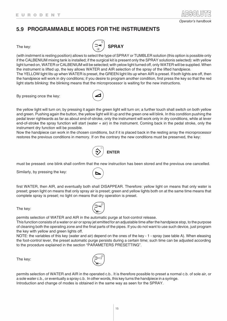
The key: SPRAY
(with instrment is resting position) allows to select the type of SPRAY or TUMBLER solution (this option is possible onlyif the CALBENIUM mixing tank is installed; if the surgical kit is present only the SPRAY solutionis selected): with yellowlight turned on, WATER or CALBENIUM will be selected; with yelow light turned off, only WATER will be supplied. Whenthe instrument is lifted up, the key allows WATER and AIR selection of the spray of the lifted handpiece.The YELLOW light lits up when WATER is preset, the GREEN light lits up when AIR is preset. If both lights are off, thenthe handpiece will work in dry conditions; if you desire to program another condition, first press the key so that the redlight starts blinking: the blinking means that the microprocessor is waiting for the new instructions.
By pressing once the key:
the yellow light will turn on; by pressing it again the green light will turn on; a further touch shall switch on both yellowand green. Pushing again the button, the yellow light will lit up and the green one will blink. In this condition pushing thepedal lever rightwards as far as about end-of-stroke, only the instrument will work only in dry conditions, while at leverend-of-stroke the spray function will start (water + air) in the instrument. Coming back in the pedal stroke, only theinstrument dry function will be possible.Now the handpiece can work in the chosen conditions, but if it is placed back in the resting array the microprocessorrestores the previous conditions in memory. If on the contrary the new conditions must be preserved, the key:
ENTER
must be pressed: one blink shall confirm that the new instruction has been stored and the previous one cancelled.
Similarly, by pressing the key:
first WATER, then AIR, and eventually both shall DISAPPEAR. Therefore: yellow light on means that only water ispreset; green light on means that only spray air is preset; green and yellow lights both on at the same time means thatcomplete spray is preset; no light on means that dry operation is preset.
The key:1
permits selection of WATER and AIR in the automatic purge at foot-control release.This function consists of a water or air or spray jet emitted for an adjustable time after the handpiece stop, to the purposeof cleaning both the operating zone and the final parts of the pipes. If you do not want to use such device, just programthe key with yellow and green lights off.NOTE: the variables of this key (water and air) depend on the ones of the key - 1 - spray (see table A). When eleasingthe foot-control lever, the preset automatic purge persists during a certain time; such time can be adjusted accordingto the procedure explained in the section “PARAMETERS PRESETTING”.
The key:2
permits selection of WATER and AIR in the operated c.b.. It is therefore possible to preset a normal c.b. of sole air, ora sole water c.b., or eventually a spray c.b. In other words, this key turns the handpiece in a syringe.Introduction and change of modes is obtained in the same way as seen for the SPRAY.
16
Operator’s handbook
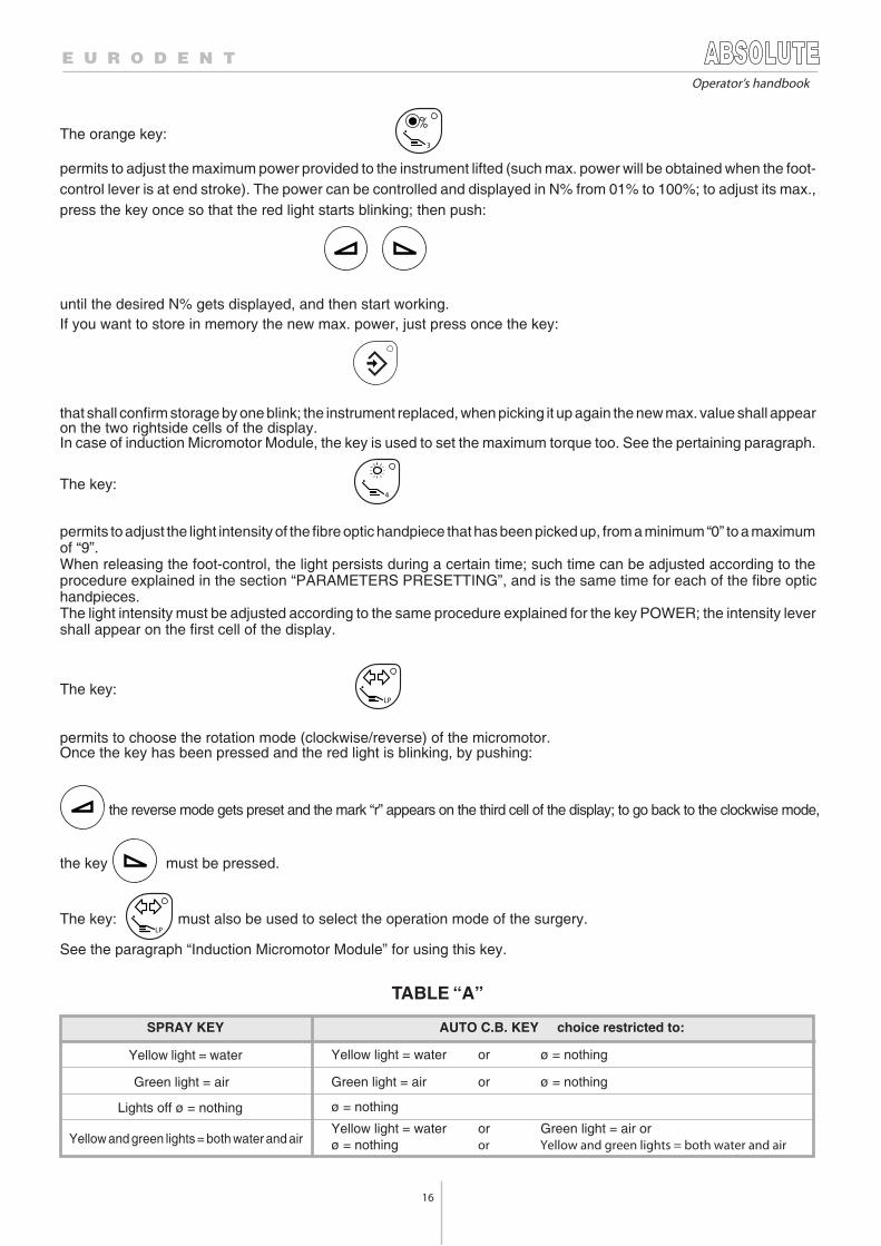
The orange key:3
permits to adjust the maximum power provided to the instrument lifted (such max. power will be obtained when the foot-control lever is at end stroke). The power can be controlled and displayed in N% from 01% to 100%; to adjust its max.,press the key once so that the red light starts blinking; then push:
until the desired N% gets displayed, and then start working.If you want to store in memory the new max. power, just press once the key:
that shall confirm storage by one blink; the instrument replaced, when picking it up again the new max. value shall appearon the two rightside cells of the display.In case of induction Micromotor Module, the key is used to set the maximum torque too. See the pertaining paragraph.
The key:4
permits to adjust the light intensity of the fibre optic handpiece that has been picked up, from a minimum “0” to a maximumof “9”.When releasing the foot-control, the light persists during a certain time; such time can be adjusted according to theprocedure explained in the section “PARAMETERS PRESETTING”, and is the same time for each of the fibre optichandpieces.The light intensity must be adjusted according to the same procedure explained for the key POWER; the intensity levershall appear on the first cell of the display.
The key:LP
permits to choose the rotation mode (clockwise/reverse) of the micromotor.Once the key has been pressed and the red light is blinking, by pushing:
the reverse mode gets preset and the mark “r” appears on the third cell of the display; to go back to the clockwise mode,
the key must be pressed.
The key: LP
must also be used to select the operation mode of the surgery.
See the paragraph “Induction Micromotor Module” for using this key.
TABLE “A”
SPRAY KEY AUTO C.B. KEY choice restricted to:
Yellow light = water Yellow light = water or ø = nothing
Green light = air Green light = air or ø = nothing
Lights off ø = nothing ø = nothing
Yellow and green lights = both water and airYellow light = water or Green light = air orø = nothing or Yellow and green lights = both water and air
17
Operator’s handbook
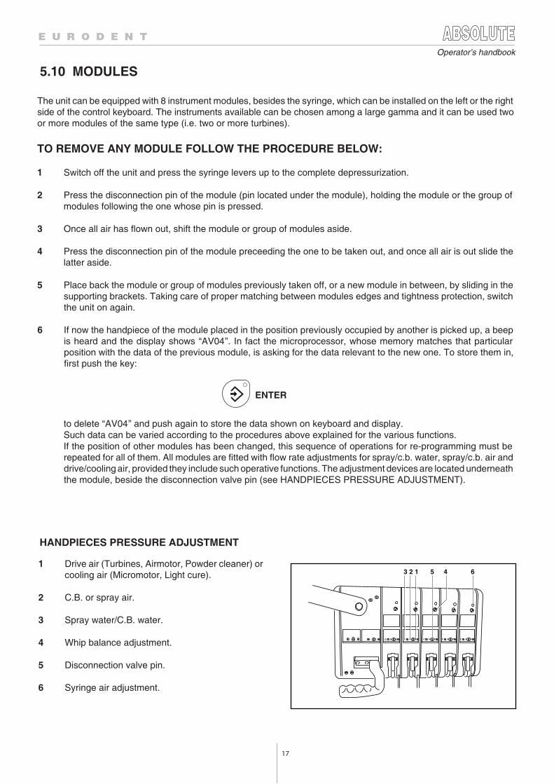
HANDPIECES PRESSURE ADJUSTMENT
5 4 63 2 1
5.10 MODULES
The unit can be equipped with 8 instrument modules, besides the syringe, which can be installed on the left or the rightside of the control keyboard. The instruments available can be chosen among a large gamma and it can be used twoor more modules of the same type (i.e. two or more turbines).
TO REMOVE ANY MODULE FOLLOW THE PROCEDURE BELOW:
1 Switch off the unit and press the syringe levers up to the complete depressurization.
2 Press the disconnection pin of the module (pin located under the module), holding the module or the group ofmodules following the one whose pin is pressed.
3 Once all air has flown out, shift the module or group of modules aside.
4 Press the disconnection pin of the module preceeding the one to be taken out, and once all air is out slide thelatter aside.
5 Place back the module or group of modules previously taken off, or a new module in between, by sliding in thesupporting brackets. Taking care of proper matching between modules edges and tightness protection, switchthe unit on again.
6 If now the handpiece of the module placed in the position previously occupied by another is picked up, a beepis heard and the display shows “AV04”. In fact the microprocessor, whose memory matches that particularposition with the data of the previous module, is asking for the data relevant to the new one. To store them in,first push the key:
ENTER
to delete “AV04” and push again to store the data shown on keyboard and display.Such data can be varied according to the procedures above explained for the various functions.If the position of other modules has been changed, this sequence of operations for re-programming must berepeated for all of them. All modules are fitted with flow rate adjustments for spray/c.b. water, spray/c.b. air anddrive/cooling air, provided they include such operative functions. The adjustment devices are located underneaththe module, beside the disconnection valve pin (see HANDPIECES PRESSURE ADJUSTMENT).
1 Drive air (Turbines, Airmotor, Powder cleaner) orcooling air (Micromotor, Light cure).
2 C.B. or spray air.
3 Spray water/C.B. water.
4 Whip balance adjustment.
5 Disconnection valve pin.
6 Syringe air adjustment.
18
Operator’s handbook
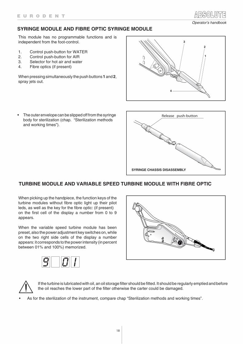
SYRINGE CHASSIS DISASSEMBLY
4
1
2
3
Release push-button
SYRINGE MODULE AND FIBRE OPTIC SYRINGE MODULE
• The outer envelope can be slipped off from the syringebody for sterilization (chap. “Sterilization methodsand working times”).
This module has no programmable functions and isindependent from the foot-control.
1. Control push-button for WATER2. Control push-button for AIR3. Selector for hot air and water4. Fibre optics (if present)
When pressing simultaneously the push buttons 1 and 2,spray jets out.
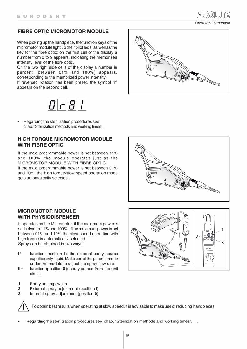
TURBINE MODULE AND VARIABLE SPEED TURBINE MODULE WITH FIBRE OPTIC
When picking up the handpiece, the function keys of theturbine modules without fibre optic light up their pilotleds, as well as the key for the fibre optic: (if present)on the first cell of the display a number from 0 to 9appears.
When the variable speed turbine module has beenpreset, also the power adjustment key switches on, whileon the two right side cells of the display a numberappears: it corresponds to the power intensity (in percentbetween 01% and 100%) memorized.
If the turbine is lubricated with oil, an oil storage filter should be fitted. It should be regularly emptied and beforethe oil reaches the lower part of the filter otherwise the carter could be damaged.
• As for the sterilization of the instrument, compare chap “Sterilization methods and working times”.
19
Operator’s handbook
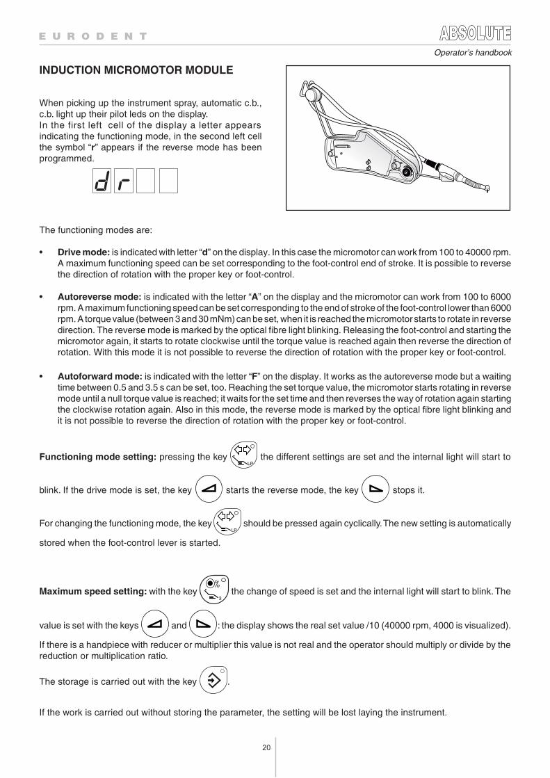
FIBRE OPTIC MICROMOTOR MODULE
• Regarding the sterilization procedures see
chap. “Sterilization methods and working times” .
HIGH TORQUE MICROMOTOR MODULE WITH FIBRE OPTIC
MICROMOTOR MODULE WITH PHYSIODISPENSER
2
1
3
To obtain best results when operating at slow speed, it is advisable to make use of reducing handpieces.
• Regarding the sterilization procedures see chap. “Sterilization methods and working times”. .
When picking up the handpiece, the function keys of themicromotor module light up their pilot leds, as well as thekey for the fibre optic: on the first cell of the display anumber from 0 to 9 appears, indicating the memorizedintensity level of the fibre optic.On the two right side cells of the display a number inpercent (between 01% and 100%) appears,corresponding to the memorized power intensity.If reversed rotation has been preset, the symbol “r”appears on the second cell.
If the max. programmable power is set between 11%and 100%, the module operates just as theMICROMOTOR MODULE WITH FIBRE OPTIC.If the max. programmable power is set between 01%and 10%, the high torque/slow speed operation modegets automatically selected.
It operates as the Micromotor, if the maximum power isset between 11% and 100%. If the maximum power is setbetween 01% and 10% the slow-speed operation withhigh torque is automatically selected.Spray can be obtained in two ways:
I a function (position I ): the external spray sourcesupplies only liquid. Make use of the potentiometerunder the module to adjust the spray flow rate.
II a function (position 0 ): spray comes from the unitcircuit
1 Spray setting switch2 External spray adjustment (position I)3 Internal spray adjustment (position 0)
20
Operator’s handbook
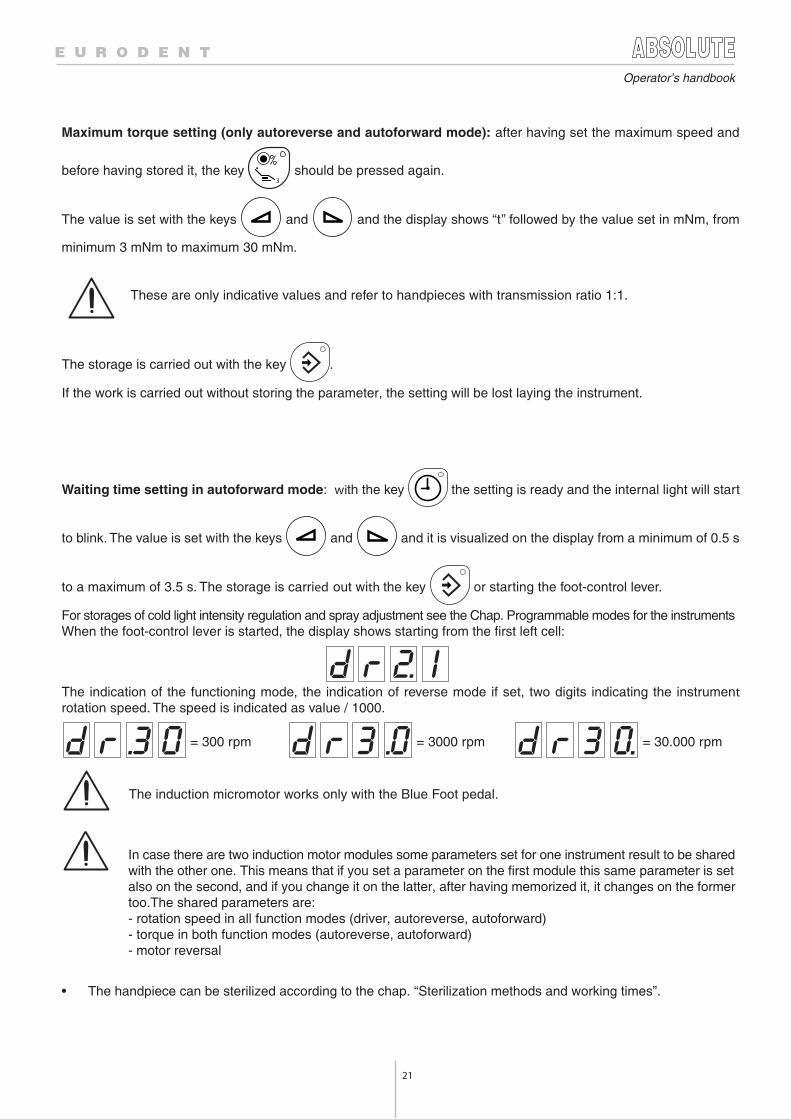
INDUCTION MICROMOTOR MODULE
When picking up the instrument spray, automatic c.b.,c.b. light up their pilot leds on the display.In the first left cell of the display a letter appearsindicating the functioning mode, in the second left cellthe symbol “r” appears if the reverse mode has beenprogrammed.
The functioning modes are:
• Drive mode: is indicated with letter “d” on the display. In this case the micromotor can work from 100 to 40000 rpm.A maximum functioning speed can be set corresponding to the foot-control end of stroke. It is possible to reversethe direction of rotation with the proper key or foot-control.
• Autoreverse mode: is indicated with the letter “A” on the display and the micromotor can work from 100 to 6000rpm. A maximum functioning speed can be set corresponding to the end of stroke of the foot-control lower than 6000rpm. A torque value (between 3 and 30 mNm) can be set, when it is reached the micromotor starts to rotate in reversedirection. The reverse mode is marked by the optical fibre light blinking. Releasing the foot-control and starting themicromotor again, it starts to rotate clockwise until the torque value is reached again then reverse the direction ofrotation. With this mode it is not possible to reverse the direction of rotation with the proper key or foot-control.
• Autoforward mode: is indicated with the letter “F” on the display. It works as the autoreverse mode but a waitingtime between 0.5 and 3.5 s can be set, too. Reaching the set torque value, the micromotor starts rotating in reversemode until a null torque value is reached; it waits for the set time and then reverses the way of rotation again startingthe clockwise rotation again. Also in this mode, the reverse mode is marked by the optical fibre light blinking andit is not possible to reverse the direction of rotation with the proper key or foot-control.
Functioning mode setting: pressing the key LP
the different settings are set and the internal light will start to
blink. If the drive mode is set, the key starts the reverse mode, the key stops it.
For changing the functioning mode, the key LP
should be pressed again cyclically. The new setting is automatically
stored when the foot-control lever is started.
Maximum speed setting: with the key 3
the change of speed is set and the internal light will start to blink. The
value is set with the keys and : the display shows the real set value /10 (40000 rpm, 4000 is visualized).
If there is a handpiece with reducer or multiplier this value is not real and the operator should multiply or divide by thereduction or multiplication ratio.
The storage is carried out with the key .
If the work is carried out without storing the parameter, the setting will be lost laying the instrument.
21
Operator’s handbook
Maximum torque setting (only autoreverse and autoforward mode): after having set the maximum speed and
before having stored it, the key 3
should be pressed again.
The value is set with the keys and and the display shows “t” followed by the value set in mNm, from
minimum 3 mNm to maximum 30 mNm.
These are only indicative values and refer to handpieces with transmission ratio 1:1.
The storage is carried out with the key .
If the work is carried out without storing the parameter, the setting will be lost laying the instrument.
Waiting time setting in autoforward mode: with the key the setting is ready and the internal light will start
to blink. The value is set with the keys and and it is visualized on the display from a minimum of 0.5 s
to a maximum of 3.5 s. The storage is carried out with the key or starting the foot-control lever.
For storages of cold light intensity regulation and spray adjustment see the Chap. Programmable modes for the instrumentsWhen the foot-control lever is started, the display shows starting from the first left cell:
The indication of the functioning mode, the indication of reverse mode if set, two digits indicating the instrumentrotation speed. The speed is indicated as value / 1000.
= 300 rpm = 3000 rpm = 30.000 rpm
The induction micromotor works only with the Blue Foot pedal.
• The handpiece can be sterilized according to the chap. “Sterilization methods and working times”.
In case there are two induction motor modules some parameters set for one instrument result to be sharedwith the other one. This means that if you set a parameter on the first module this same parameter is setalso on the second, and if you change it on the latter, after having memorized it, it changes on the formertoo.The shared parameters are:- rotation speed in all function modes (driver, autoreverse, autoforward) - torque in both function modes (autoreverse, autoforward) - motor reversal
22
Operator’s handbook
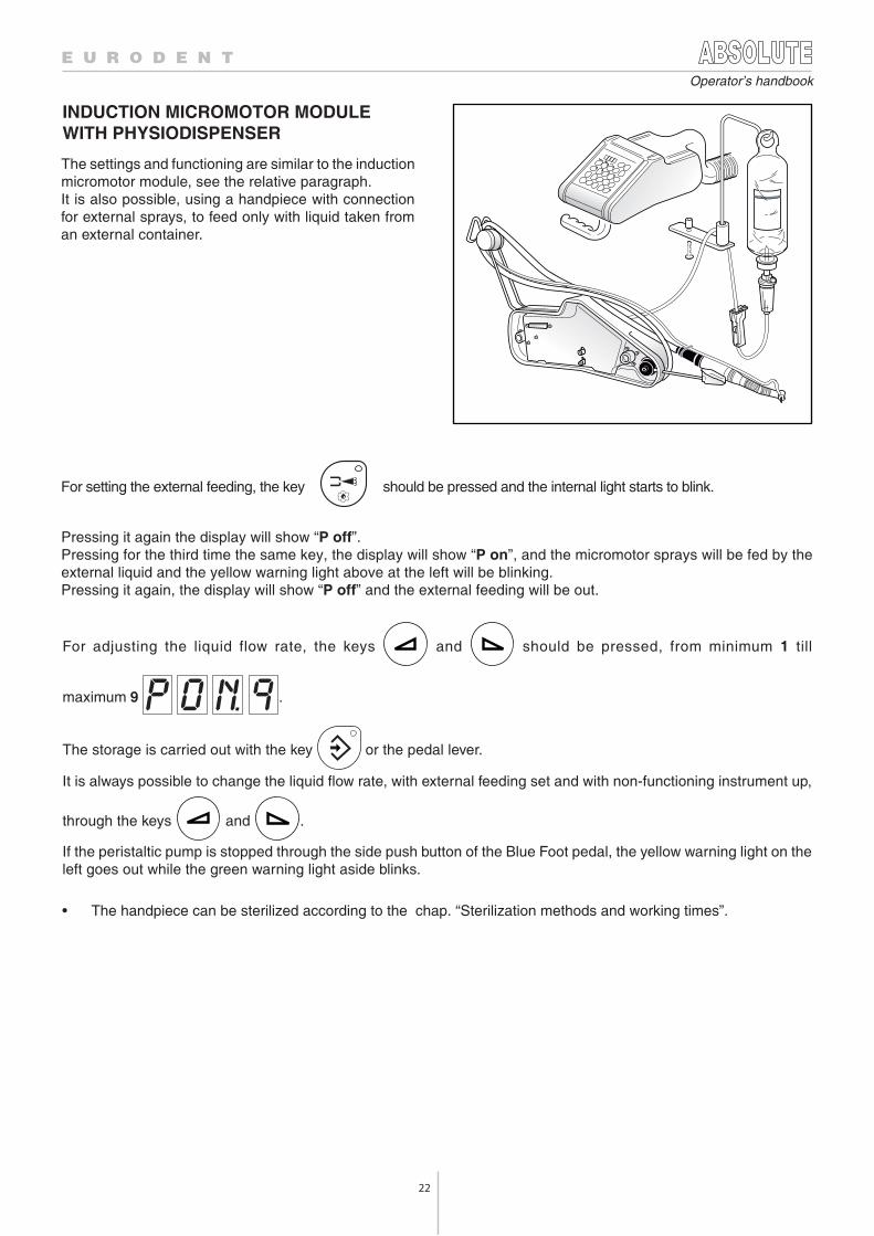
INDUCTION MICROMOTOR MODULEWITH PHYSIODISPENSER
The settings and functioning are similar to the inductionmicromotor module, see the relative paragraph.It is also possible, using a handpiece with connectionfor external sprays, to feed only with liquid taken froman external container.
For setting the external feeding, the key should be pressed and the internal light starts to blink.
Pressing it again the display will show “P off”.Pressing for the third time the same key, the display will show “P on”, and the micromotor sprays will be fed by theexternal liquid and the yellow warning light above at the left will be blinking.Pressing it again, the display will show “P off” and the external feeding will be out.
• The handpiece can be sterilized according to the chap. “Sterilization methods and working times”.
For adjusting the liquid flow rate, the keys and should be pressed, from minimum 1 till
maximum 9 .
The storage is carried out with the key or the pedal lever.
It is always possible to change the liquid flow rate, with external feeding set and with non-functioning instrument up,
through the keys and .
If the peristaltic pump is stopped through the side push button of the Blue Foot pedal, the yellow warning light on theleft goes out while the green warning light aside blinks.
23
Operator’s handbook
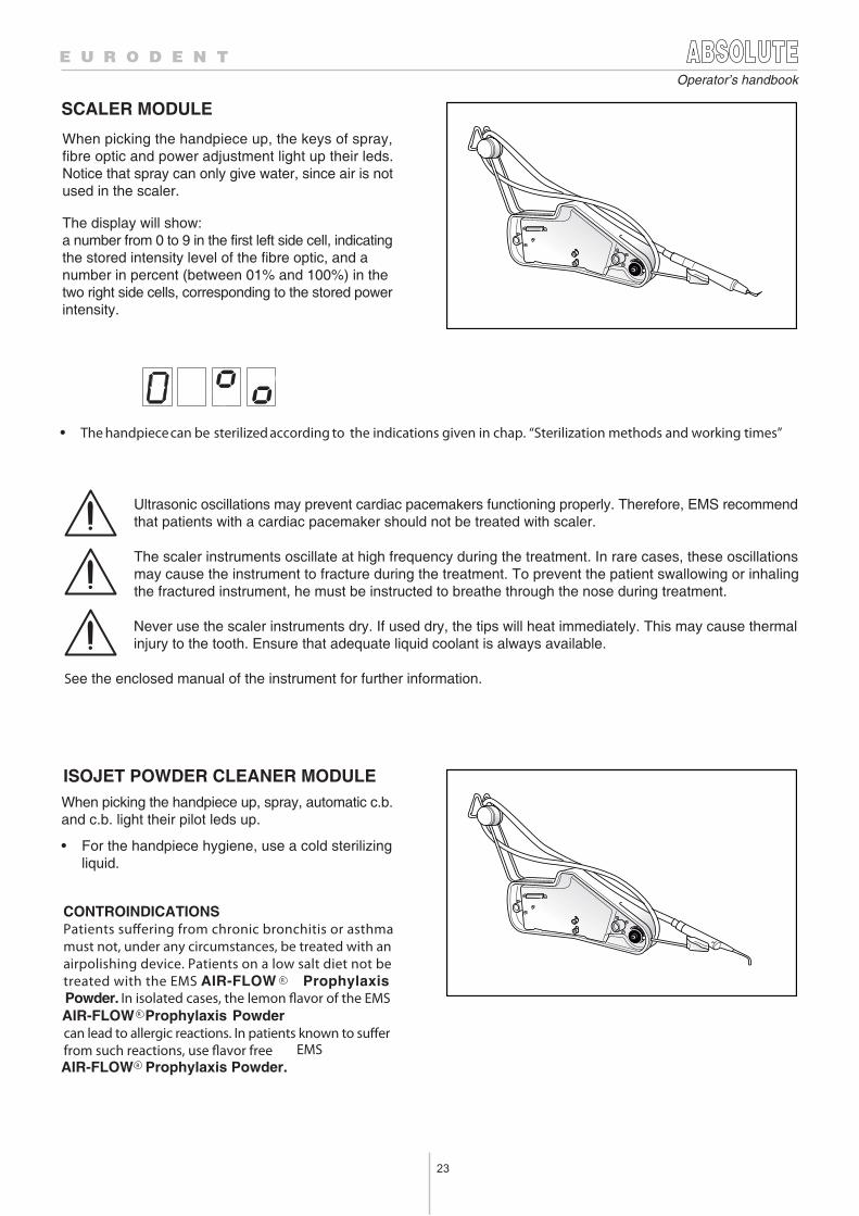
SCALER MODULE
ISOJET POWDER CLEANER MODULE
When picking the handpiece up, the keys of spray,fibre optic and power adjustment light up their leds.Notice that spray can only give water, since air is notused in the scaler.
The display will show:a number from 0 to 9 in the first left side cell, indicatingthe stored intensity level of the fibre optic, and anumber in percent (between 01% and 100%) in thetwo right side cells, corresponding to the stored powerintensity.
• The handpiece can be sterilized according to the indications given in chap. “Sterilization methods and working times”
Ultrasonic oscillations may prevent cardiac pacemakers functioning properly. Therefore, EMS recommendthat patients with a cardiac pacemaker should not be treated with scaler.
The scaler instruments oscillate at high frequency during the treatment. In rare cases, these oscillationsmay cause the instrument to fracture during the treatment. To prevent the patient swallowing or inhalingthe fractured instrument, he must be instructed to breathe through the nose during treatment.
Never use the scaler instruments dry. If used dry, the tips will heat immediately. This may cause thermalinjury to the tooth. Ensure that adequate liquid coolant is always available.
See the enclosed manual of the instrument for further information.
When picking the handpiece up, spray, automatic c.b.and c.b. light their pilot leds up.
• For the handpiece hygiene, use a cold sterilizingliquid.
CONTROINDICATIONSPatients suffering from chronic bronchitis or asthma must not, under any circumstances, be treated with an airpolishing device. Patients on a low salt diet not be treated with the EMS AIR-FLOW Prophylaxis Powder. In isolated cases, the lemon flavor of the EMS AIR-FLOW Prophylaxis Powdercan lead to allergic reactions. In patients known to suffer from such reactions, use flavor free EMS AIR-FLOW Prophylaxis Powder.
R
R
R
24
Operator’s handbook
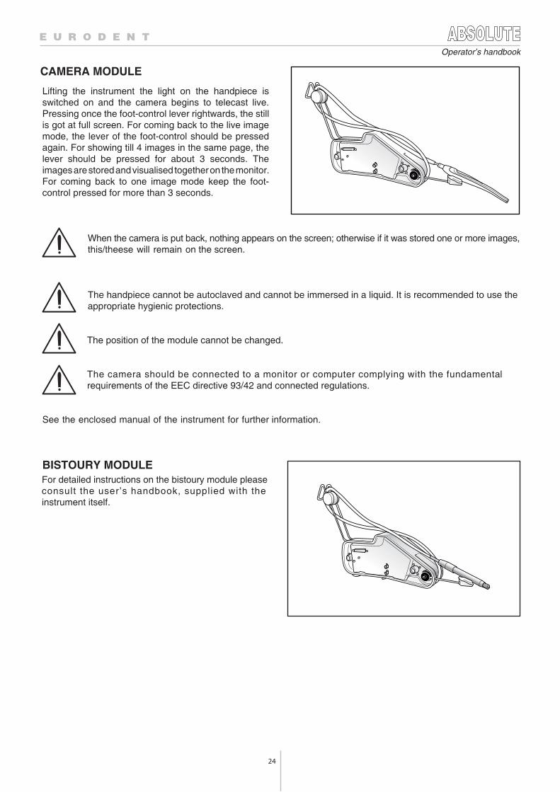
CAMERA MODULE
BISTOURY MODULEFor detailed instructions on the bistoury module pleaseconsult the user’s handbook, supplied with theinstrument itself.
Lifting the instrument the light on the handpiece isswitched on and the camera begins to telecast live.Pressing once the foot-control lever rightwards, the stillis got at full screen. For coming back to the live imagemode, the lever of the foot-control should be pressedagain. For showing till 4 images in the same page, thelever should be pressed for about 3 seconds. Theimages are stored and visualised together on the monitor.For coming back to one image mode keep the foot-control pressed for more than 3 seconds.
When the camera is put back, nothing appears on the screen; otherwise if it was stored one or more images,this/theese will remain on the screen.
The handpiece cannot be autoclaved and cannot be immersed in a liquid. It is recommended to use theappropriate hygienic protections.
The position of the module cannot be changed.
The camera should be connected to a monitor or computer complying with the fundamentalrequirements of the EEC directive 93/42 and connected regulations.
See the enclosed manual of the instrument for further information.

25
Operator’s handbook
MINI LED LIGHT CURE MODULE
1
2
3
4
5
This module has no programmable functions and isindependent from the foot-control.
For starting the instrument, press the push-button 5placed on the side of the optical terminal. The green ledplaced underneath will light up, enabling the instrumentworking.The polimerization cycle begins pressing the keyaccording to the selected mode. The cycle can beinterrupted at any time pressing the key again. Cyclestart and end are indicated by an acoustic signal.
There are three working modes selectable with thenavigation key 1.
Fast CuringIf it is selected, the red led, placed near the symbol 4,will lit.The lamp will work for 10 s with a power of 1100 W/cm2
(110%) with the tip of ø7.5 mm.
Pulse CuringIf it is selected, the orange led, placed near the symbol3, will lit.The lamp will work at maximum power with 10 emissionsalternating with a rest period of 250 ms.
Step CuringIf it is selected, the jellow led, placed near the symbol 2,will lit.The lamp will reach full power progressively in 10 s, thenit will remain on at maximum pressure for other 10 s.
The optical tip is autoclavable according to the indicationsgiven at the chap. “Sterilization methods and working times”.
Do not point the instrument light towards the eyes.
Do not use this instrument if the patient and/or the operator has a heart stimulator or pacemaker.
Do not use on person who suffers, or has suffered in the past, from photo-biological reactions (includingurticaria solaris or protoporphyrie erythropetique), or any person receiving medical treatment and usingphotosensitive medication (including methoxsalenes or dymethylchlorotetracycline).
Any person who has previously suffered from a retina or crystalline condition or who has undergone eyesurgery, in particular cataract treatment, should visit an eye specialist before undergoing treatment with MiniLed. Even with the patient’s agreement, it is highly recommended to use protective glasses at all times.
See the enclosed manual of the instrument for further information.
26
Operator’s handbook
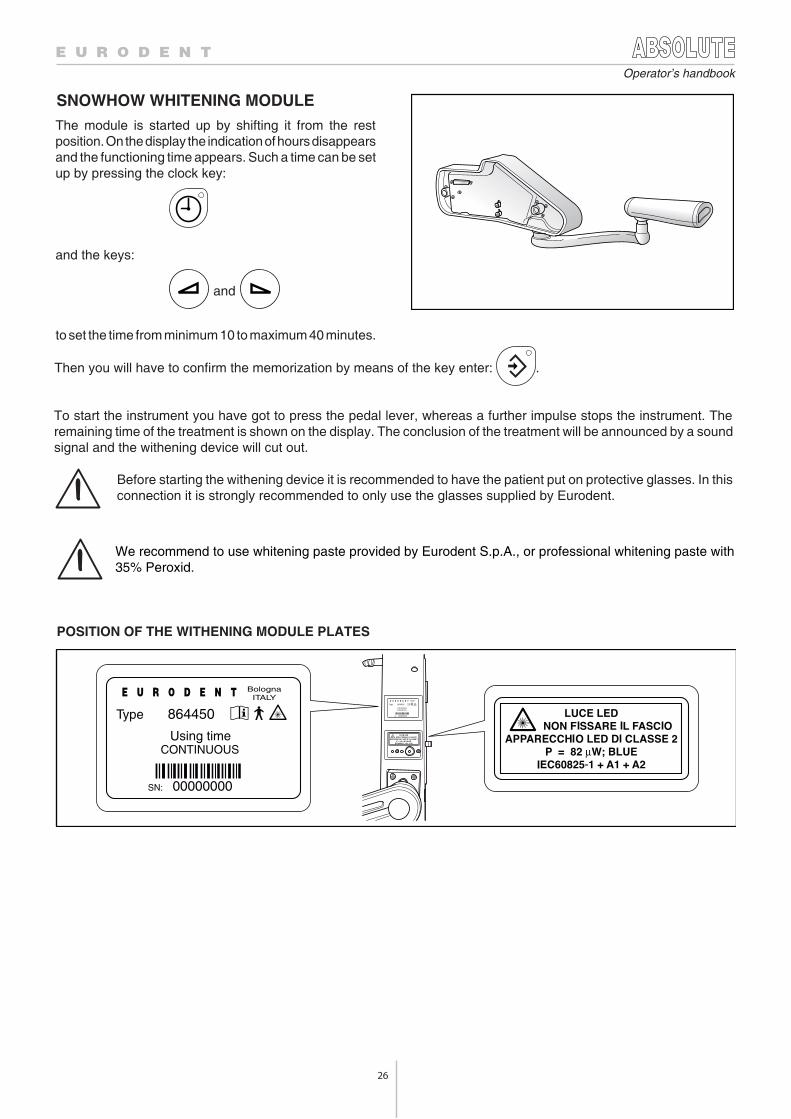
SNOWHOW WHITENING MODULE
BolognaITALY
Type 864450
Using timeCONTINUOS
SN: 00000000
BolognaITALY
Type 864450
Using timeCONTINUOUS
SN: 00000000
We recommend to use whitening paste provided by Eurodent S.p.A., or professional whitening paste with35% Peroxid.
POSITION OF THE WITHENING MODULE PLATES
The module is started up by shifting it from the restposition. On the display the indication of hours disappearsand the functioning time appears. Such a time can be setup by pressing the clock key:
and the keys:
and
to set the time from minimum 10 to maximum 40 minutes.
Then you will have to confirm the memorization by means of the key enter: .
To start the instrument you have got to press the pedal lever, whereas a further impulse stops the instrument. Theremaining time of the treatment is shown on the display. The conclusion of the treatment will be announced by a soundsignal and the withening device will cut out.
Before starting the withening device it is recommended to have the patient put on protective glasses. In thisconnection it is strongly recommended to only use the glasses supplied by Eurodent.
27
Operator’s handbook
5.11 ASEPSIS MODE
5.12 MESSAGES EXPLANATION
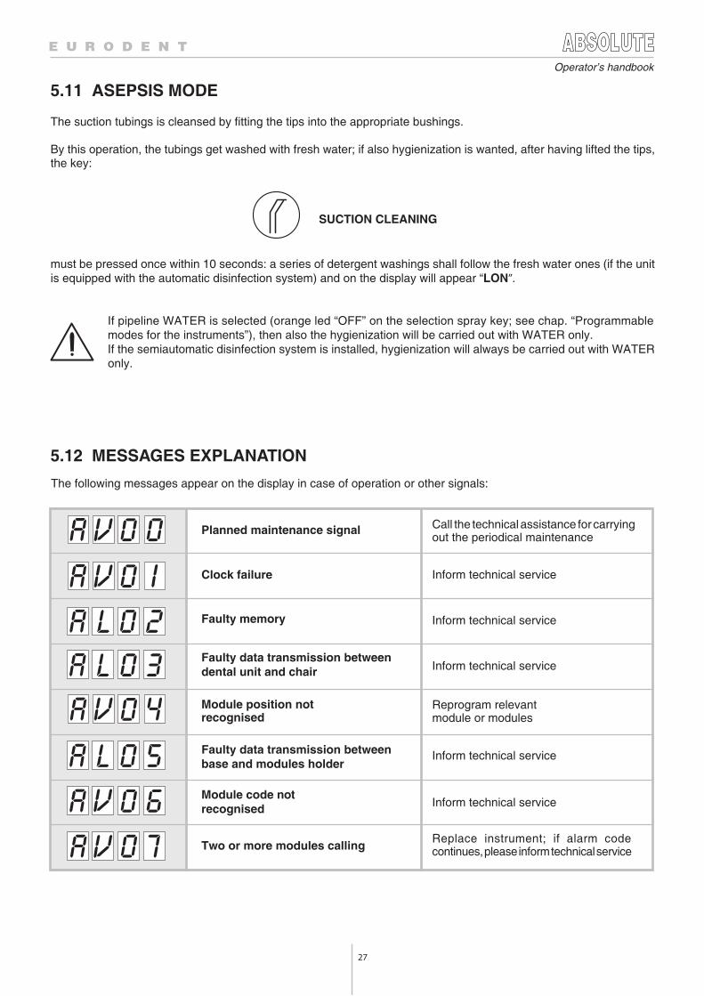
The suction tubings is cleansed by fitting the tips into the appropriate bushings.
By this operation, the tubings get washed with fresh water; if also hygienization is wanted, after having lifted the tips,the key:
SUCTION CLEANING
must be pressed once within 10 seconds: a series of detergent washings shall follow the fresh water ones (if the unitis equipped with the automatic disinfection system) and on the display will appear “LON”.
If pipeline WATER is selected (orange led “OFF” on the selection spray key; see chap. “Programmablemodes for the instruments”), then also the hygienization will be carried out with WATER only.If the semiautomatic disinfection system is installed, hygienization will always be carried out with WATERonly.
The following messages appear on the display in case of operation or other signals:
Planned maintenance signal Call the technical assistance for carryingout the periodical maintenance
Clock failure
Faulty memory
Faulty data transmission betweendental unit and chair
Module position notrecognised
Module code notrecognised
Faulty data transmission betweenbase and modules holder
Two or more modules callingReplace instrument; if alarm codecontinues, please inform technical service
Inform technical service
Inform technical service
Inform technical service
Inform technical service
Inform technical service
Reprogram relevantmodule or modules
28
Operator’s handbook
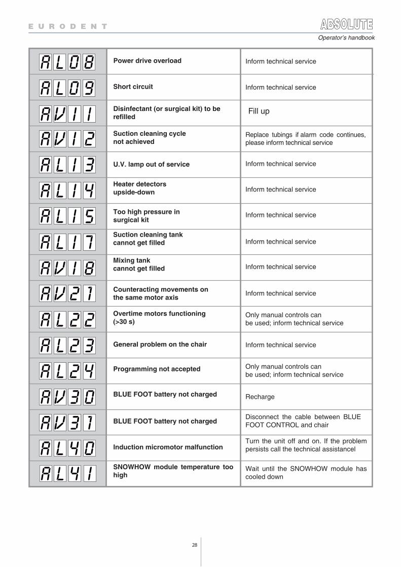
Power drive overload
Disinfectant (or surgical kit) to berefilled
Suction cleaning cyclenot achieved
Heater detectorsupside-down
Programming not accepted
Suction cleaning tankcannot get filled Inform technical service
Mixing tankcannot get filled Inform technical service
Counteracting movements onthe same motor axis
Inform technical service
Overtime motors functioning(>30 s)
Only manual controls canbe used; inform technical service
General problem on the chair Inform technical service
Only manual controls canbe used; inform technical service
Inform technical service
Inform technical service
Replace tubings if alarm code continues,please inform technical service
Too high pressure insurgical kit
Inform technical service
BLUE FOOT battery not charged Recharge
BLUE FOOT battery not chargedDisconnect the cable between BLUEFOOT CONTROL and chair
U.V. lamp out of service Inform technical service
Induction micromotor malfunction Turn the unit off and on. If the problem
persists call the technical assistancel
SNOWHOW module temperature toohigh
Wait until the SNOWHOW module hascooled down
Short circuit Inform technical service
Fill up
29
Operator’s handbook
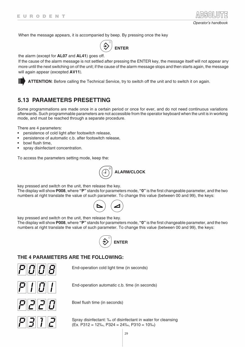
5.13 PARAMETERS PRESETTING
End-operation cold light time (in seconds)
End-operation automatic c.b. time (in seconds)
Bowl flush time (in seconds)
Spray disinfectant: ‰ of disinfectant in water for cleansing(Ex. P312 = 12‰, P324 = 24‰, P310 = 10‰)
When the message appears, it is accompanied by beep. By pressing once the key
ENTER
the alarm (except for AL07 and AL41) goes off.If the cause of the alarm message is not settled after pressing the ENTER key, the message itself will not appear anymore until the next switching on of the unit; if the cause of the alarm message stops and then starts again, the messagewill again appear (excepted AV11).
ATTENTION: Before calling the Technical Service, try to switch off the unit and to switch it on again.
Some programmations are made once in a certain period or once for ever, and do not need continuous variationsafterwards. Such programmable parameters are not accessible from the operator keyboard when the unit is in workingmode, and must be reached through a separate procedure.
There are 4 parameters:• persistence of cold light after footswitch release,• persistence of automatic c.b. after footswitch release,• bowl flush time,• spray disinfectant concentration.
To access the parameters setting mode, keep the:
ALARM/CLOCK
key pressed and switch on the unit, then release the key.The display will show P008, where “P” stands for parameters mode, “0” is the first changeable parameter, and the twonumbers at right translate the value of such parameter. To change this value (between 00 and 99), the keys:
key pressed and switch on the unit, then release the key.The display will show P008, where “P” stands for parameters mode, “0” is the first changeable parameter, and the twonumbers at right translate the value of such parameter. To change this value (between 00 and 99), the keys:
ENTER
THE 4 PARAMETERS ARE THE FOLLOWING:
30
Operator’s handbook
6.1 GENERAL DESCRIPTION OF THE DISPLAY
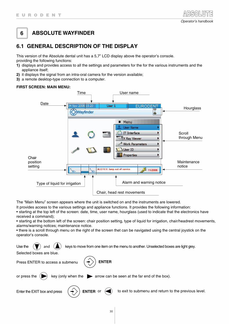
This version of the Absolute dental unit has a 5,7” LCD display above the operator’s console. providing the following functions:1) displays and provides access to all the settings and parameters for the for the various instruments and the
appliance itself;2) it displays the signal from an intra-oral camera for the version available;3) a remote desktop-type connection to a computer.
FIRST SCREEN: MAIN MENU:
Use the keys to move from one item on the menu to another. Unselected boxes are light grey. and
Selected boxes are blue.
Press ENTER to access a submenu ENTER
or press the key (only when the arrow can be seen at the far end of the box).
ABSOLUTE WAYFINDER6
Date
Chairpositionsetting
Time User name
Scrollthrough Menu
Hourglass
Maintenancenotice
Type of liquid for irrigation Alarm and warning notice
The “Main Menu” screen appears where the unit is switched on and the instruments are lowered. It provides access to the various settings and appliance functions. It provides the following information: • starting at the top left of the screen: date, time, user name, hourglass (used to indicate that the electronics have received a command);• starting at the bottom left of the screen: chair position setting, type of liquid for irrigation, chair/headrest movements, alarms/warning notices; maintenance notice.• there is a scroll through menu on the right of the screen thet can be navigated using the central joystick on the operator’s console.
Chair, head rest movements
Enter the EXIT box and press
or to exit to submenu and return to the previous level. ENTER
31
Operator’s handbook
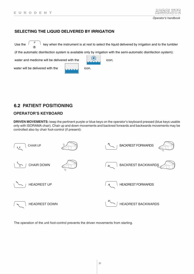
6.2 PATIENT POSITIONING
CHAIR UP BACKREST FORWARDS
CHAIR DOWN BACKREST BACKWARDS
HEADREST UP HEADREST FORWARDS
HEADREST DOWN HEADREST BACKWARDS
The operation of the unit foot-control prevents the driven movements from starting.
OPERATOR’S KEYBOARD
DRIVEN MOVEMENTS: keep the pertinent purple or blue keys on the operator’s keyboard pressed (blue keys usableonly with ISORAMA chair). Chair up and down movements and backrest forwards and backwards movements may becontrolled also by chair foot-control (if present):
SELECTING THE LIQUID DELIVERED BY IRRIGATION
PUse the key when the instrument is at rest to select the liquid delivered by irrigation and to the tumbler
(if the automatic disinfection system is available only by irrigation with the semi-automatic disinfection system):
water and medicine will be delivered with the icon;
water will be delivered with the icon.
32
Operator’s handbook
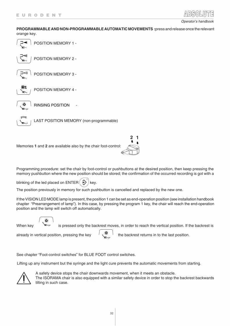
Memories 1 and 2 are available also by the chair foot-control:
When key is pressed only the backrest moves, in order to reach the vertical position. If the backrest is
already in vertical position, pressing the key the backrest returns in to the last position.
See chapter “Foot-control switches” for BLUE FOOT control switches..
POSITION MEMORY 1 -
POSITION MEMORY 2 -
POSITION MEMORY 3 -
POSITION MEMORY 4 -
RINSING POSITION -
LAST POSITION MEMORY (non-programmable)
12
PROGRAMMABLE AND NON-PROGRAMMABLE AUTOMATIC MOVEMENTS :press and release once the relevant orange key.
1
3
2
4
Programming procedure: set the chair by foot-control or pushbuttons at the desired position, then keep pressing thememory pushbutton where the new position should be stored; the confirmation of the occurred recording is got with a
blinking of the led placed on ENTER key.
The position previously in memory for such pushbutton is cancelled and replaced by the new one.
If the VISION LED MODE lamp is present, the position 1 can be set as end-operation position (see installation handbookchapter “Prearrangement of lamp”). In this case, by pressing the program 1 key, the chair will reach the end-operationposition and the lamp will switch off automatically.
Lifting up any instrument but the syringe and the light cure prevents the automatic movements from starting.
A safety device stops the chair downwards movement, when it meets an obstacle.The ISORAMA chair is also equipped with a similar safety device in order to stop the backrest backwardstilting in such case.
33
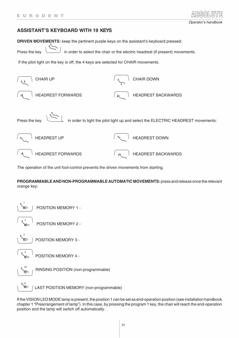
If the pilot light on the key is off, the 4 keys are selected for CHAIR movements.
Operator’s handbook
ASSISTANT’S KEYBOARD WITH 19 KEYS
DRIVEN MOVEMENTS: keep the pertinent purple keys on the assistant’s keyboard pressed:
Press the key in order to select the chair or the electric headrest (if present) movements.
The operation of the unit foot-control prevents the driven movements from starting.
CHAIR UP CHAIR DOWN
HEADREST FORWARDS HEADREST BACKWARDS
Press the key in order to light the pilot light up and select the ELECTRIC HEADREST movements:
HEADREST UP HEADREST DOWN
HEADREST FORWARDS HEADREST BACKWARDS
POSITION MEMORY 1 -
POSITION MEMORY 2 -
POSITION MEMORY 3 -
POSITION MEMORY 4 -
1
2
3
4
LP
SP
PROGRAMMABLE AND NON-PROGRAMMABLE AUTOMATIC MOVEMENTS: press and release once the relevantorange key:
RINSING POSITION (non-programmable)
LAST POSITION MEMORY (non-programmable)
If the VISION LED MODE lamp is present, the position 1 can be set as end-operation position (see installation handbookchapter 1 “Prearrangement of lamp”). In this case, by pressing the program 1 key, the chair will reach the end-operationposition and the lamp will switch off automatically.
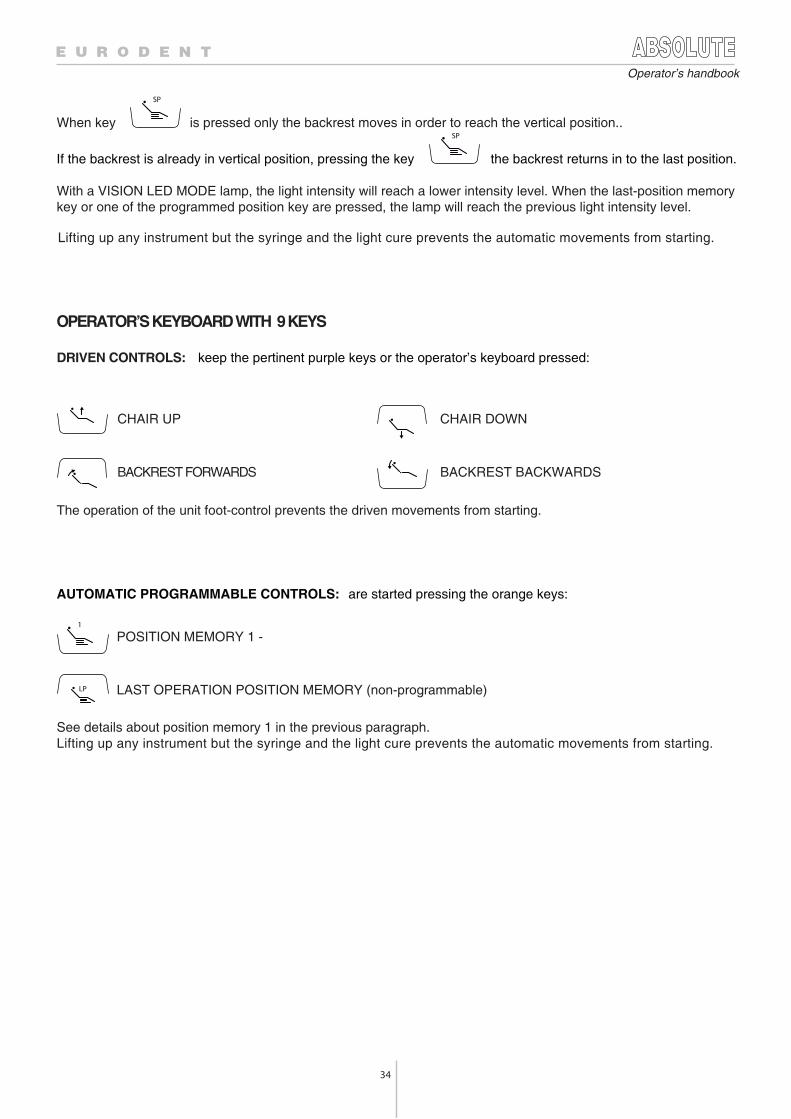
34
Operator’s handbook
When key
SP
is pressed only the backrest moves in order to reach the vertical position..
If the backrest is already in vertical position, pressing the key
SP
the backrest returns in to the last position.
With a VISION LED MODE lamp, the light intensity will reach a lower intensity level. When the last-position memory key or one of the programmed position key are pressed, the lamp will reach the previous light intensity level.
Lifting up any instrument but the syringe and the light cure prevents the automatic movements from starting.
OPERATOR’S KEYBOARD WITH 9 KEYS
DRIVEN CONTROLS: keep the pertinent purple keys or the operator’s keyboard pressed:
The operation of the unit foot-control prevents the driven movements from starting.
CHAIR UP CHAIR DOWN
BACKREST FORWARDS BACKREST BACKWARDS
AUTOMATIC PROGRAMMABLE CONTROLS: are started pressing the orange keys:
POSITION MEMORY 1 -
LAST OPERATION POSITION MEMORY (non-programmable)
See details about position memory 1 in the previous paragraph.Lifting up any instrument but the syringe and the light cure prevents the automatic movements from starting.
POLTRONA ISO3000 (POGGIATESTA)
A riguardo della movimentazione del poggiatesta bisogna fare due considerazioni: 1) quando il poggiatest a è tutto inserito nella s palliera oppure è u scito solo per una parte, prima di poterlo ruotare è
necessario farlo uscire no a circa metà corsa; questo fatto viene segnalato da un avvertimento (“Alzare poggiatesta” situato nella casella “allarmi/avvertimenti”) se il dentista vuole ruotare il poggiatesta prima che sia uscito della corsa necessaria;
2) quando il poggiatesta è alzato oltre la metà corsa ed è in una posizione inclinata, per poterlo abbassare, e quindi inserire nella spalliera, bisogna prima allinearlo con quest’ultima; questo fatto viene segnalato da un avvertimento (“Allineare poggiatesta con spalliera” situato nella casella “allarmi/avvertimenti”) se il dentista vuole abbassare il poggiatesta prima di averlo allineato con la spalliera.
1
LP
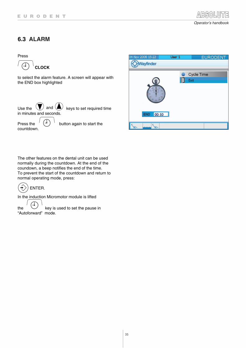
35
Operator’s handbook
Press
CLOCK
to select the alarm feature. A screen will appear with the END box highlighted
Use the and keys to set required time in minutes and seconds.
The other features on the dental unit can be used normally during the countdown. At the end of the coundown, a beep notifies the end of the time. To prevent the start of the countdown and return tonormal operating mode, press:
ENTER.
In the induction Micromotor module is lifted
the key is used to set the pause in “Autoforward” mode.
6.3 ALARM
Press the button again to start the countdown.
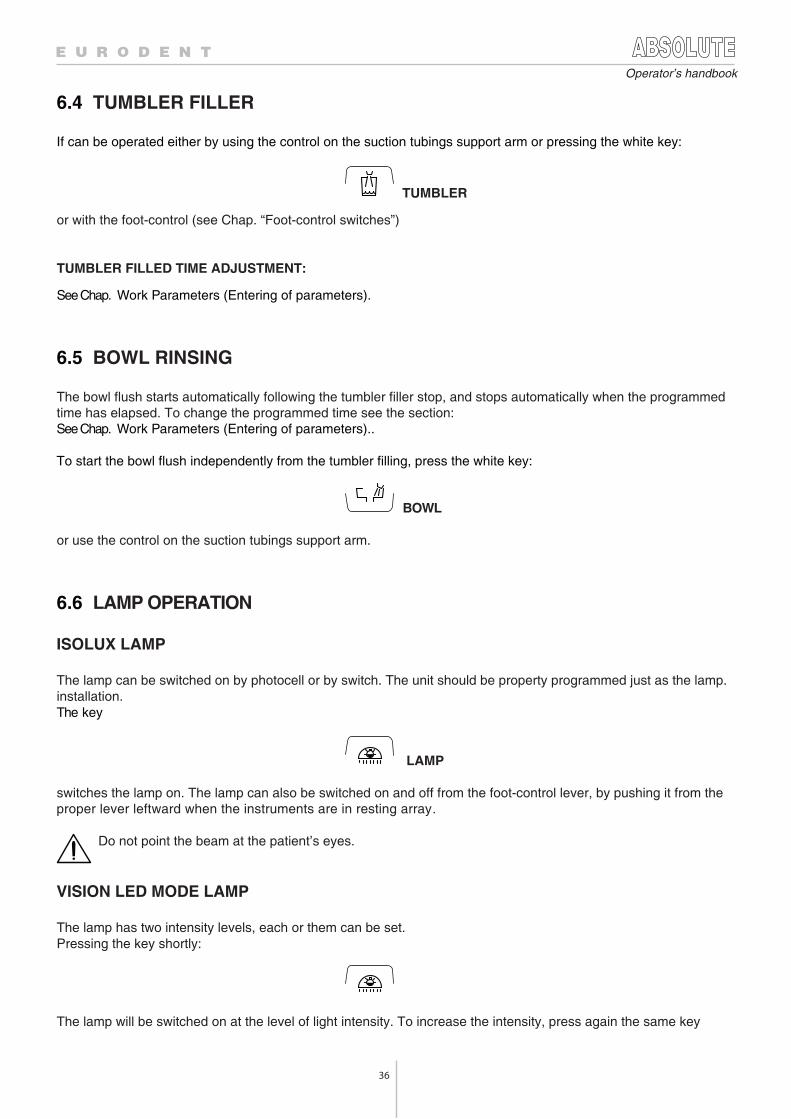
36
Operator’s handbook
6.4 TUMBLER FILLER
If can be operated either by using the control on the suction tubings support arm or pressing the white key:
TUMBLER
or with the foot-control (see Chap. “Foot-control switches”)
TUMBLER FILLED TIME ADJUSTMENT:
See Chap. Work Parameters (Entering of parameters).
6.5 BOWL RINSING
The bowl flush starts automatically following the tumbler filler stop, and stops automatically when the programmed time has elapsed. To change the programmed time see the section: See Chap. Work Parameters (Entering of parameters)..
To start the bowl flush independently from the tumbler filling, press the white key:
BOWL
or use the control on the suction tubings support arm.
6.6 LAMP OPERATION
ISOLUX LAMP
The lamp can be switched on by photocell or by switch. The unit should be property programmed just as the lamp.installation.The key
LAMP
switches the lamp on. The lamp can also be switched on and off from the foot-control lever, by pushing it from the proper lever leftward when the instruments are in resting array.
Do not point the beam at the patient’s eyes.
VISION LED MODE LAMP
The lamp has two intensity levels, each or them can be set.Pressing the key shortly:
The lamp will be switched on at the level of light intensity. To increase the intensity, press again the same key
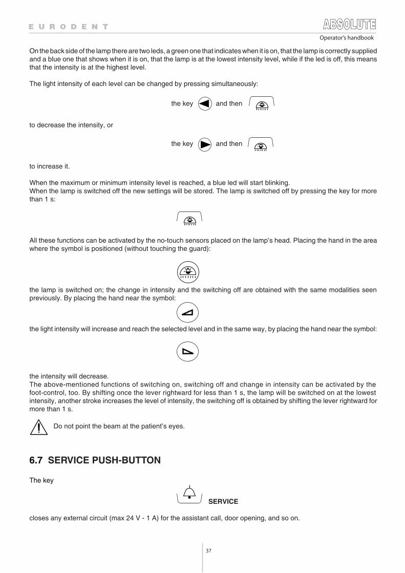
37
Operator’s handbook
On the back side of the lamp there are two leds, a green one that indicates when it is on, that the lamp is correctly suppliedand a blue one that shows when it is on, that the lamp is at the lowest intensity level, while if the led is off, this meansthat the intensity is at the highest level.
The light intensity of each level can be changed by pressing simultaneously:
the key and then
the key and then
to decrease the intensity, or
to increase it.
When the maximum or minimum intensity level is reached, a blue led will start blinking.When the lamp is switched off the new settings will be stored. The lamp is switched off by pressing the key for morethan 1 s:
All these functions can be activated by the no-touch sensors placed on the lamp’s head. Placing the hand in the areawhere the symbol is positioned (without touching the guard):
the lamp is switched on; the change in intensity and the switching off are obtained with the same modalities seenpreviously. By placing the hand near the symbol:
the light intensity will increase and reach the selected level and in the same way, by placing the hand near the symbol:
the intensity will decrease.The above-mentioned functions of switching on, switching off and change in intensity can be activated by thefoot-control, too. By shifting once the lever rightward for less than 1 s, the lamp will be switched on at the lowestintensity, another stroke increases the level of intensity, the switching off is obtained by shifting the lever rightward formore than 1 s.
Do not point the beam at the patient’s eyes.
6.7 SERVICE PUSH-BUTTON
The key
SERVICE
closes any external circuit (max 24 V - 1 A) for the assistant call, door opening, and so on.
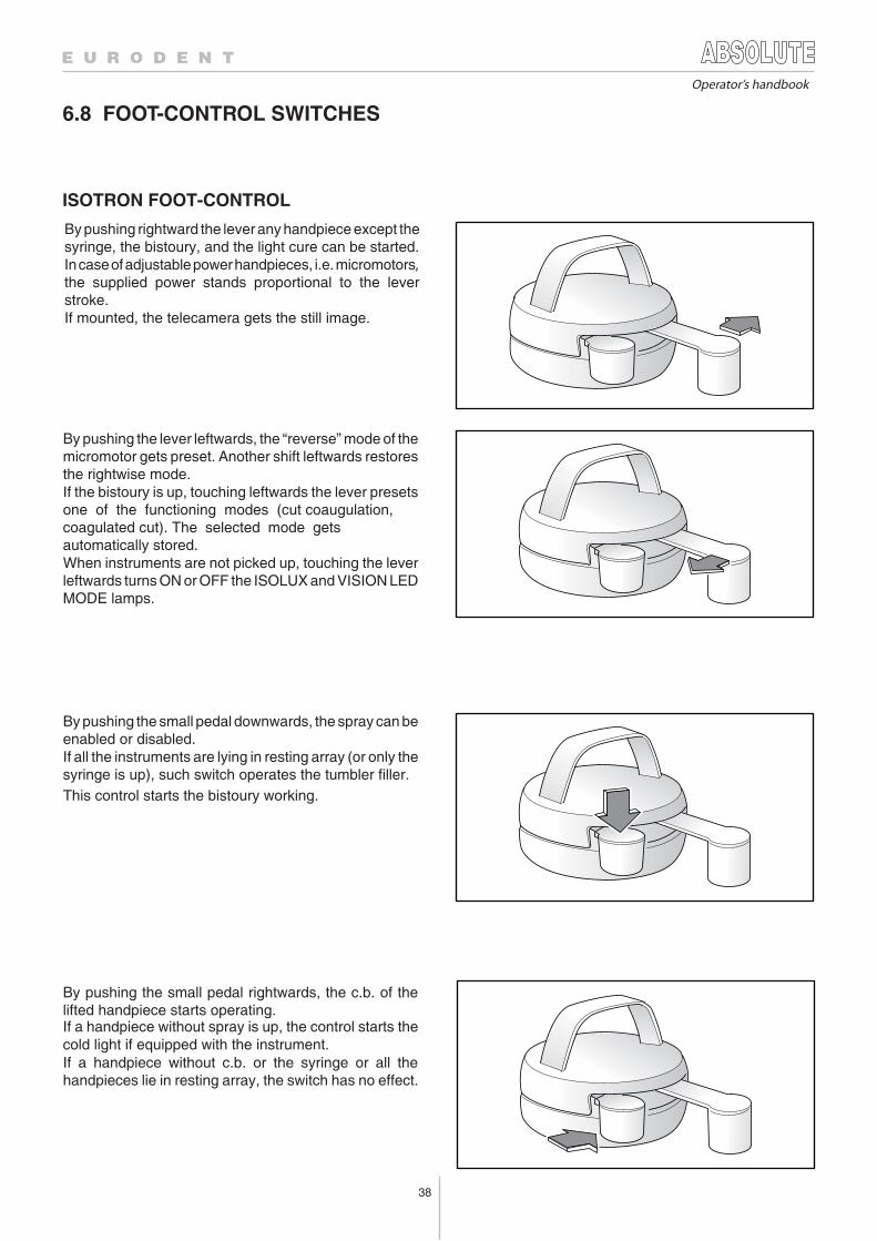
38
6.8 FOOT-CONTROL SWITCHES
ISOTRON FOOT-CONTROL
Operator’s handbook
By pushing rightward the lever any handpiece except thesyringe, the bistoury, and the light cure can be started.In case of adjustable power handpieces, i.e. micromotors,the supplied power stands proportional to the leverstroke.If mounted, the telecamera gets the still image.
By pushing the lever leftwards, the “reverse” mode of themicromotor gets preset. Another shift leftwards restoresthe rightwise mode.If the bistoury is up, touching leftwards the lever presetsone of the functioning modes (cut coaugulation,coagulated cut). The selected mode gets automatically stored.When instruments are not picked up, touching the leverleftwards turns ON or OFF the ISOLUX and VISION LEDMODE lamps.
By pushing the small pedal downwards, the spray can beenabled or disabled.If all the instruments are lying in resting array (or only thesyringe is up), such switch operates the tumbler filler.
If a handpiece without spray is up, the control starts thecold light if equipped with the instrument.
This control starts the bistoury working.
By pushing the small pedal rightwards, the c.b. of thelifted handpiece starts operating.
If a handpiece without c.b. or the syringe or all thehandpieces lie in resting array, the switch has no effect.
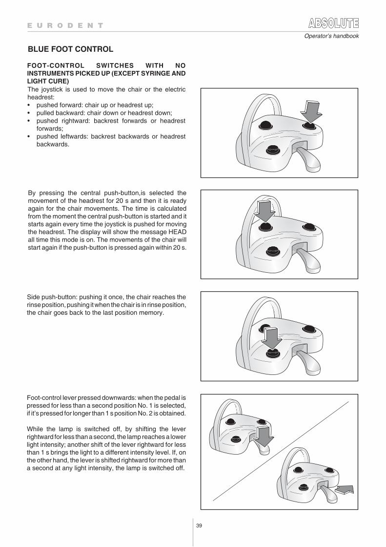
39
Operator’s handbook
BLUE FOOT CONTROL
The joystick is used to move the chair or the electricheadrest:• pushed forward: chair up or headrest up;• pulled backward: chair down or headrest down;• pushed rightward: backrest forwards or headrest
forwards;• pushed leftwards: backrest backwards or headrest
backwards.
Foot-control lever pressed downwards: when the pedal ispressed for less than a second position No. 1 is selected,if it’s pressed for longer than 1 s position No. 2 is obtained.
While the lamp is switched off, by shifting the leverrightward for less than a second, the lamp reaches a lowerlight intensity; another shift of the lever rightward for lessthan 1 s brings the light to a different intensity level. If, onthe other hand, the lever is shifted rightward for more thana second at any light intensity, the lamp is switched off.
Side push-button: pushing it once, the chair reaches therinse position, pushing it when the chair is in rinse position,the chair goes back to the last position memory.
By pressing the central push-button,is selected themovement of the headrest for 20 s and then it is readyagain for the chair movements. The time is calculatedfrom the moment the central push-button is started and itstarts again every time the joystick is pushed for movingthe headrest. The display will show the message HEADall time this mode is on. The movements of the chair willstart again if the push-button is pressed again within 20 s.
FOOT-CONTROL SWITCHES WITH NOINSTRUMENTS PICKED UP (EXCEPT SYRINGE ANDLIGHT CURE)
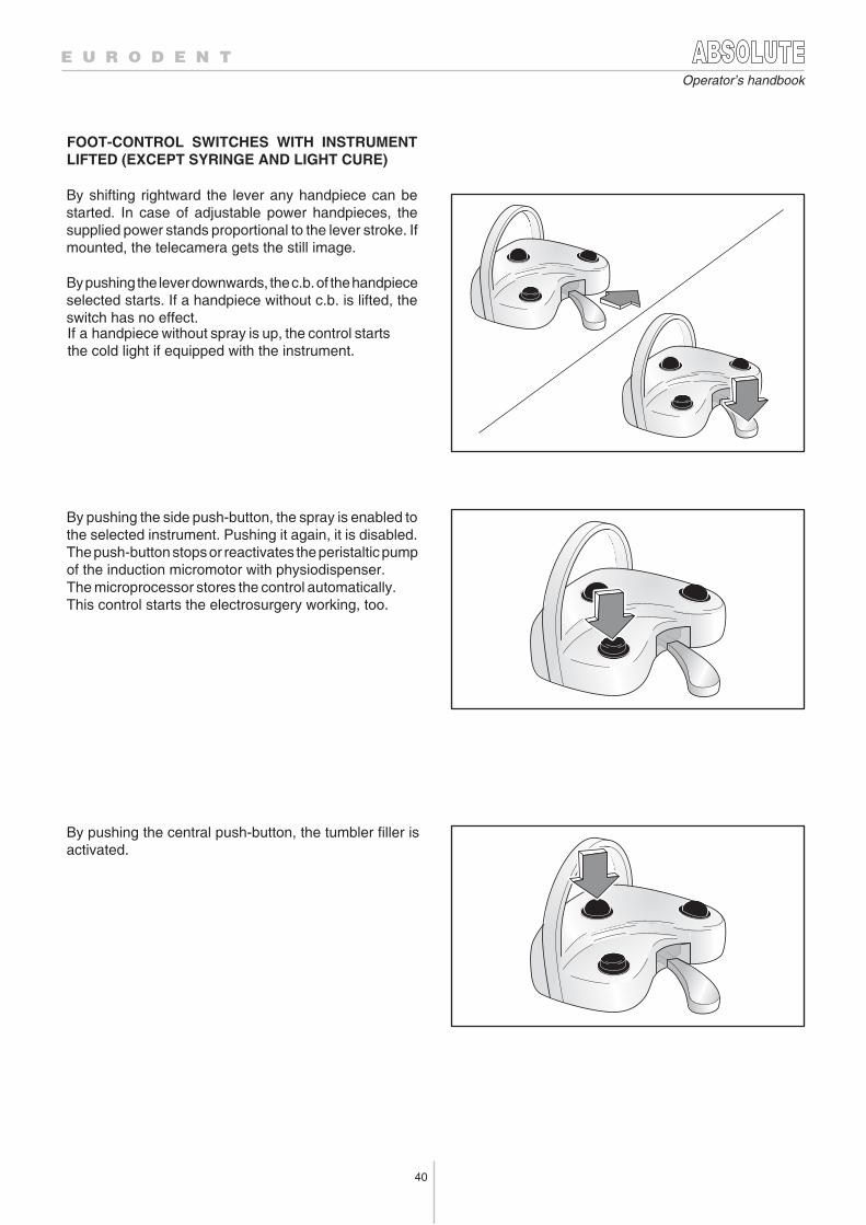
40
Operator’s handbook
By pushing the side push-button, the spray is enabled tothe selected instrument. Pushing it again, it is disabled.The push-button stops or reactivates the peristaltic pumpof the induction micromotor with physiodispenser.The microprocessor stores the control automatically. This control starts the electrosurgery working, too.
By pushing the central push-button, the tumbler filler isactivated.
By shifting rightward the lever any handpiece can bestarted. In case of adjustable power handpieces, thesupplied power stands proportional to the lever stroke. Ifmounted, the telecamera gets the still image.
By pushing the lever downwards, the c.b. of the handpieceselected starts. If a handpiece without c.b. is lifted, theswitch has no effect.
FOOT-CONTROL SWITCHES WITH INSTRUMENTLIFTED (EXCEPT SYRINGE AND LIGHT CURE)
If a handpiece without spray is up, the control starts the cold light if equipped with the instrument.
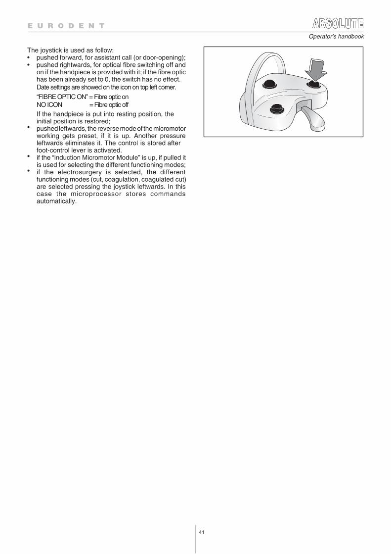
41
Operator’s handbook
The joystick is used as follow:• pushed forward, for assistant call (or door-opening);• pushed rightwards, for optical fibre switching off and
on if the handpiece is provided with it; if the fibre optichas been already set to 0, the switch has no effect.Date settings are showed on the icon on top left corner.
“FIBRE OPTIC ON” = Fibre optic onNO ICON = Fibre optic off If the handpiece is put into resting position, the initial position is restored;
• pushed leftwards, the reverse mode of the micromotorworking gets preset, if it is up. Another pressureleftwards eliminates it. The control is stored after foot-control lever is activated.
• if the “induction Micromotor Module” is up, if pulled itis used for selecting the different functioning modes;
• if the electrosurgery is selected, the differentfunctioning modes (cut, coagulation, coagulated cut)are selected pressing the joystick leftwards. In thiscase the microprocessor stores commandsautomatically.
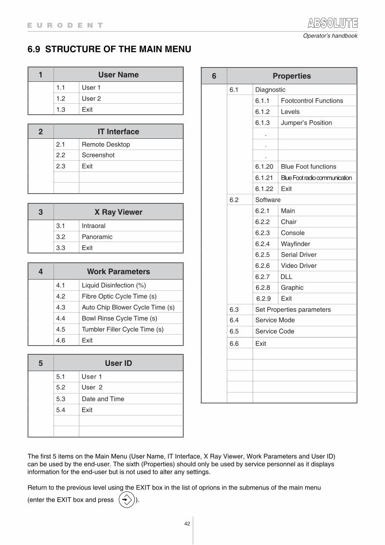
42
Operator’s handbook
6.9 STRUCTURE OF THE MAIN MENU
1 User Name
1.1 User 1
1.2 User 2
1.3 Exit
2 IT Interface
2.1 Remote Desktop
2.2 Screenshot
2.3 Exit
3 X Ray Viewer
3.1 Intraoral
3.2 Panoramic
3.3 Exit
4 Work Parameters
4.1 Liquid Disinfection (%)
4.2 Fibre Optic Cycle Time (s)
4.3 Auto Chip Blower Cycle Time (s)
4.4 Bowl Rinse Cycle Time (s)
4.5 Tumbler Filler Cycle Time (s)
4.6 Exit
5 User ID
5.3 Date and Time
5.4 Exit
5.2 User 2
5.1 User 1
The first 5 items on the Main Menu (User Name, IT Interface, X Ray Viewer, Work Parameters and User ID) can be used by the end-user. The sixth (Properties) should only be used by service personnel as it displays information for the end-user but is not used to alter any settings.
Return to the previous level using the EXIT box in the list of oprions in the submenus of the main menu
(enter the EXIT box and press ).
6 Properties
6.1 Diagnostic
6.1.1 Footcontrol Functions
6.1.2 Levels
6.1.3 Jumper’s Position
.
.
.
6.1.21 Blue Foot radio communication
6.1.20 Blue Foot functions
6.1.22 Exit
6.2 Software
6.2.1 Main
6.2.2 Chair
6.2.3 Console
6.2.4 Wayfinder
6.2.5 Serial Driver
6.2.6 Video Driver
6.2.7 DLL
6.3 Set Properties parameters
6.4 Service Mode
6.5 Service Code
6.6 Exit
Exit6.2.9
6.2.8 Graphic
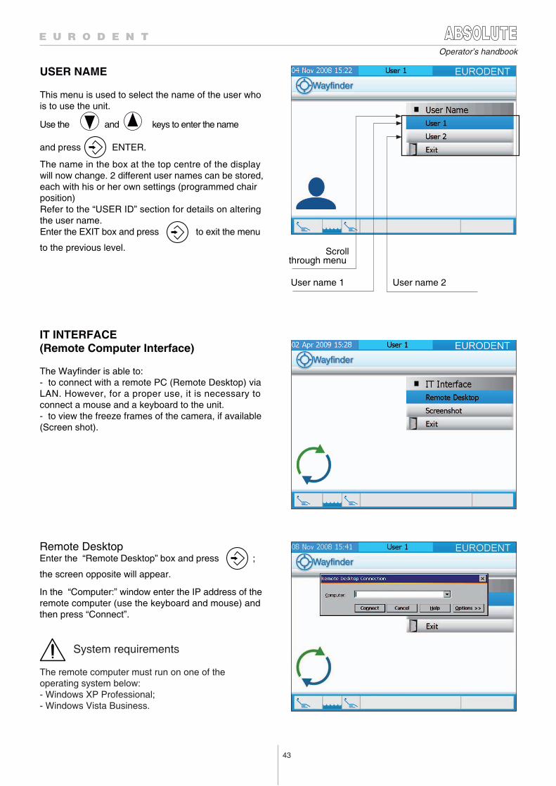
43
Operator’s handbook
Scrollthrough menu
User name 1
USER NAME
This menu is used to select the name of the user who is to use the unit.
Use the and keys to enter the name
and press ENTER.
The name in the box at the top centre of the display will now change. 2 different user names can be stored, each with his or her own settings (programmed chairposition)Refer to the “USER ID” section for details on altering the user name.Enter the EXIT box and press to exit the menu
to the previous level.
User name 2
IT INTERFACE(Remote Computer Interface)
The Wayfinder is able to:- to connect with a remote PC (Remote Desktop) viaLAN. However, for a proper use, it is necessary toconnect a mouse and a keyboard to the unit.- to view the freeze frames of the camera, if available(Screen shot).
Remote DesktopEnter the “Remote Desktop” box and press ;
the screen opposite will appear.
In the “Computer:” window enter the IP address of theremote computer (use the keyboard and mouse) and then press “Connect”.
System requirements
The remote computer must run on one of the operating system below:- Windows XP Professional;- Windows Vista Business.
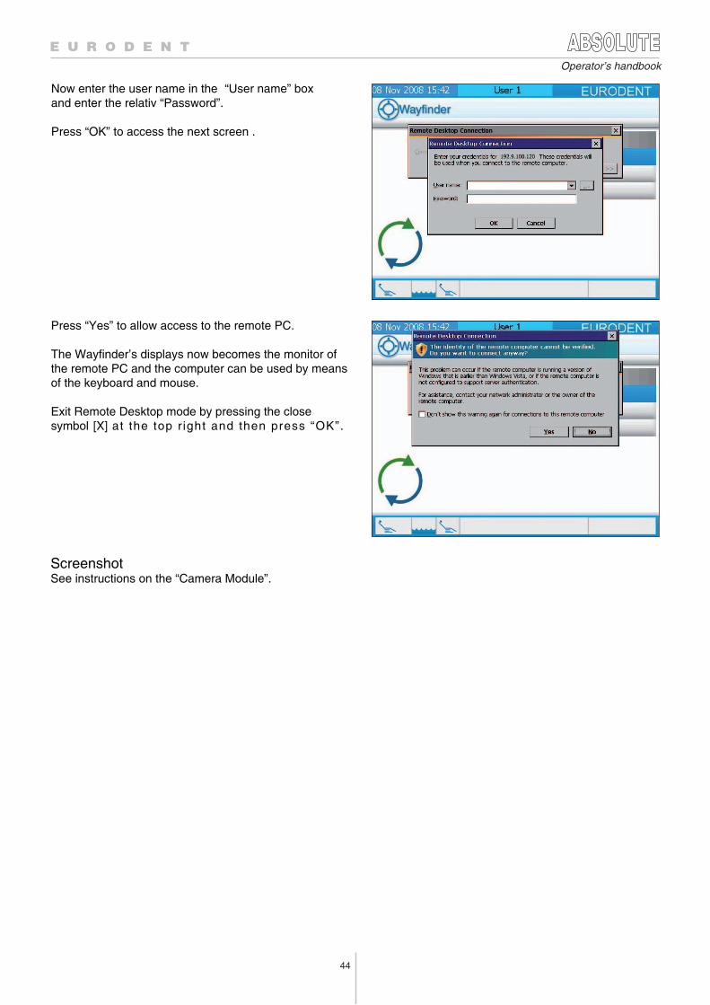
44
Operator’s handbook
ScreenshotSee instructions on the “Camera Module”.
Press “Yes” to allow access to the remote PC.
The Wayfinder’s displays now becomes the monitor ofthe remote PC and the computer can be used by meansof the keyboard and mouse.
Exit Remote Desktop mode by pressing the close symbol [X] at the top r ight and then press “OK”.
Now enter the user name in the “User name” box and enter the relativ “Password”.
Press “OK” to access the next screen .
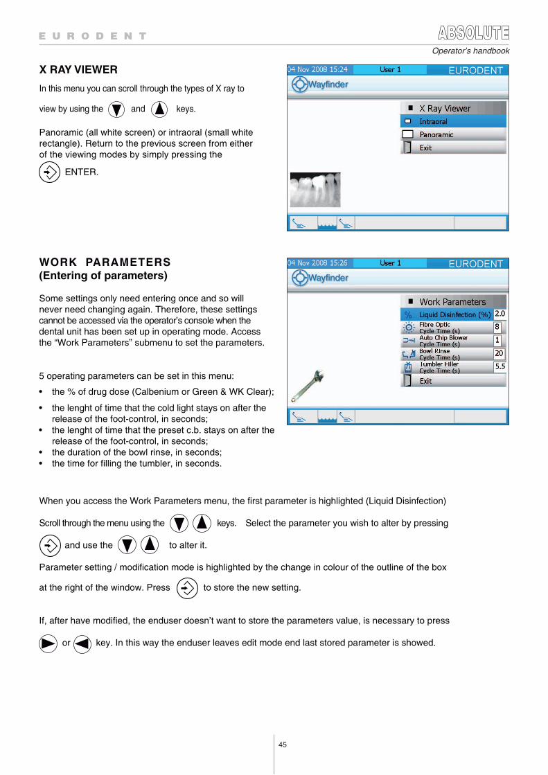
45
Operator’s handbook
X RAY VIEWER
In this menu you can scroll through the types of X ray to
view by using the keys. and
Panoramic (all white screen) or intraoral (small white
rectangle). Return to the previous screen from either
of the viewing modes by simply pressing the
ENTER.
WORK PARAMETERS (Entering of parameters)
Some settings only need entering once and so will never need changing again. Therefore, these settings cannot be accessed via the operator’s console when the dental unit has been set up in operating mode. Access the “Work Parameters” submenu to set the parameters.
5 operating parameters can be set in this menu:
• the % of drug dose (Calbenium or Green & WK Clear);
• the lenght of time that the cold light stays on after the release of the foot-control, in seconds;
• the lenght of time that the preset c.b. stays on after the release of the foot-control, in seconds;
• the duration of the bowl rinse, in seconds;• the time for filling the tumbler, in seconds.
When you access the Work Parameters menu, the first parameter is highlighted (Liquid Disinfection)
Scroll through the menu using the keys. Select the parameter you wish to alter by pressing
and use the to alter it.
Parameter setting / modification mode is highlighted by the change in colour of the outline of the box
at the right of the window. Press to store the new setting.
If, after have modified, the enduser doesn’t want to store the parameters value, is necessary to press or key. In this way the enduser leaves edit mode end last stored parameter is showed.
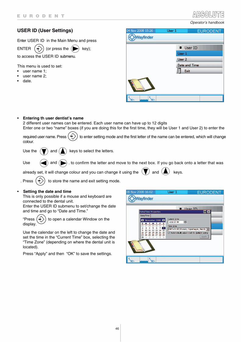
46
Operator’s handbook
USER ID (User Settings)
Enter USER ID in the Main Menu and press
ENTER (or press the key);
to access the USER ID submenu.
This menu is used to set:• user name 1;• user name 2;• date.
• Entering th user dentist’s name 2 different user names can be entered. Each user name can have up to 12 digits
Enter one or two “name” boxes (if you are doing this for the first time, they will be User 1 and User 2) to enter the
required user name. Press to enter setting mode and the first letter of the name can be entered, which will change colour.
Use the and keys to select the letters.
Use and . to confirm the letter and move to the next box. If you go back onto a letter that was
already set, it will change colour and you can change it using the and keys.
. Press to store the name and exit setting mode.
• Setting the date and timeThis is only possible if a mouse and keyboard are connected to the dental unit.Enter the USER ID submenu to set/change the date and time and go to “Date and Time.”
“Press to open a calendar Window on the display.
Use the calendar on the left to change the date and set the time in the “Current Time” box, selecting the“Time Zone” (depending on where the dental unit islocated).
Press “Apply” and then “OK” to save the settings.
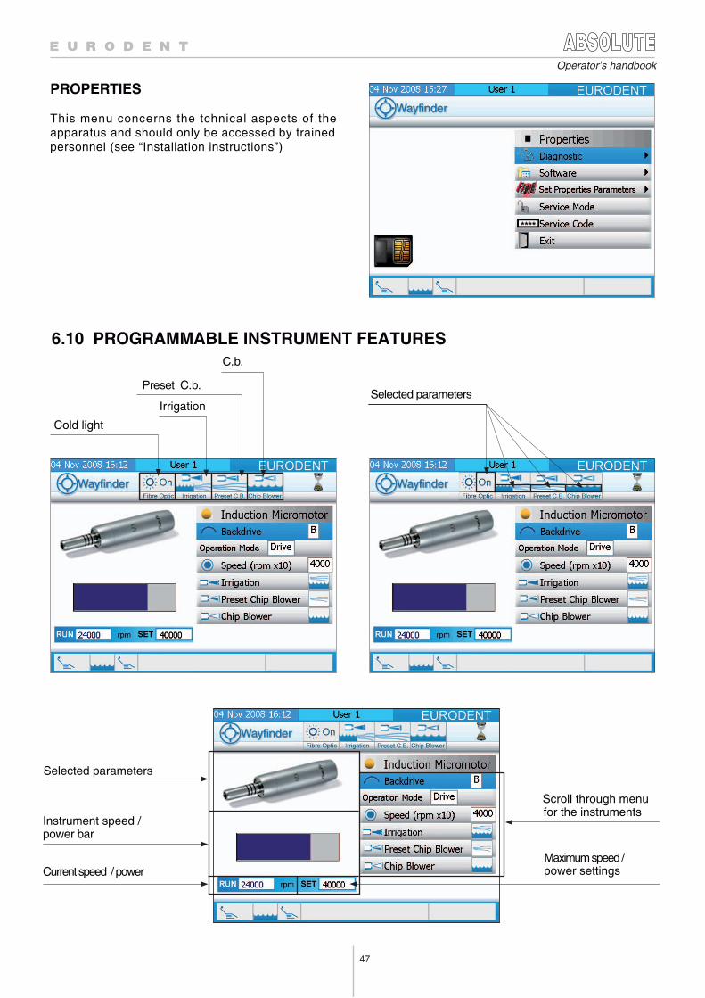
47
Operator’s handbook
PROPERTIES
This menu concerns the tchnical aspects of the apparatus and should only be accessed by trainedpersonnel (see “Installation instructions”)
6.10 PROGRAMMABLE INSTRUMENT FEATURES
Cold light
Irrigation
Preset C.b.
C.b.
Selected parameters
Selected parameters
Instrument speed /power bar
Scroll through menufor the instruments
Maximum speed / power settings Current speed / power
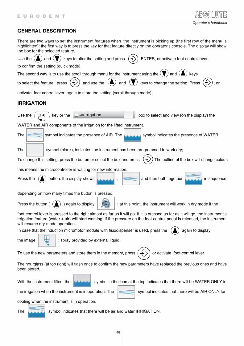
Operator’s handbook
GENERAL DESCRIPTION
There are two ways to set the instrument features when the instrument is picking up (the first row of the menu ishighlighted): the first way is to press the key for that feature directly on the operator’s console. The display will showthe box for the selected feature.
Use the and keys to alter the setting and press ENTER, or activate foot-control lever,
to confirm the setting (quick mode).
The second way is to use the scroll through menu for the instrument using the and keys
to select the feature; press and use the and keys to change the setting. Press , or
activate foot-control lever, again to store the setting (scroll through mode).
IRRIGATION
1
Use the key or the box to select and view (on the display) the
WATER and AIR components of the irrigation for the lifted instrument.
The symbol indicates the presence of AIR. The symbol indicates the presence of WATER.
The symbol (blank), indicates the instrument has been programmed to work dry;
To change this setting, press the button or select the box and press The outline of the box will change colour:
this means the microcontroller is waiting for new information.
Press the button: the display shows , and then both together in sequence,
depending on how many times the button is pressed.
Press the button ( ) again to display : at this point, the instrument will work in dry mode if the
foot-control lever is pressed to the right almost as far as it will go. If it is pressed as far as it will go, the instrument’sirrigation feature (water + air) will start working. If the pressure on the foot-control pedal is released, the instrumentwill resume dry-mode operation. .In case that the induction micromotor module with fisiodispenser is used, press the again to display
the image : spray provided by external liquid.
To use the new parameters and store them in the memory, press or activate foot-control lever.
The hourglass (at top right) will flash once to confirm the new parameters have replaced the previous ones and havebeen stored.
With the instrument lifted, the symbol in the icon at the top indicates that there will be WATER ONLY in
the irrigation when the instrument is in operation. The symbol indicates that there will be AIR ONLY for
cooling when the instrument is in operation.
The symbol indicates that there will be air and water IRRIGATION.
48
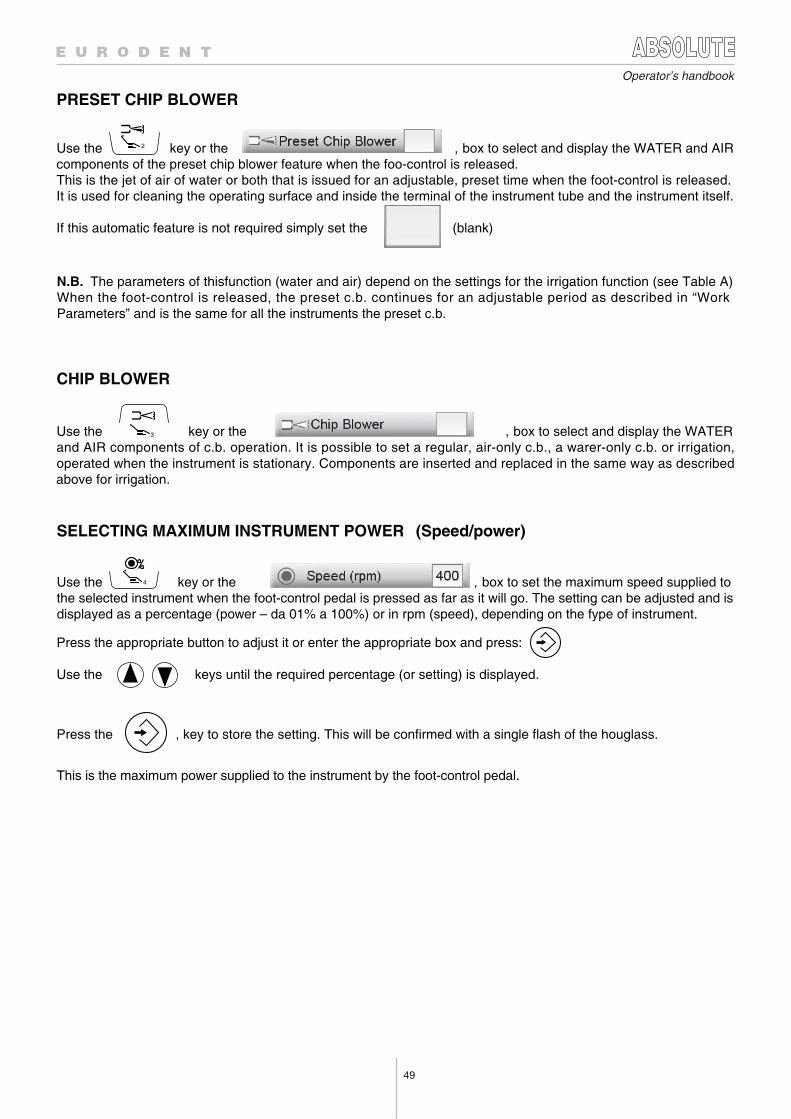
49
PRESET CHIP BLOWER
Use the 2 key or the , box to select and display the WATER and AIR components of the preset chip blower feature when the foo-control is released. This is the jet of air of water or both that is issued for an adjustable, preset time when the foot-control is released. It is used for cleaning the operating surface and inside the terminal of the instrument tube and the instrument itself.
If this automatic feature is not required simply set the (blank)
N.B. The parameters of thisfunction (water and air) depend on the settings for the irrigation function (see Table A) When the foot-control is released, the preset c.b. continues for an adjustable period as described in “Work Parameters” and is the same for all the instruments the preset c.b.
CHIP BLOWER
Use the 3 key or the , box to select and display the WATER and AIR components of c.b. operation. It is possible to set a regular, air-only c.b., a warer-only c.b. or irrigation,operated when the instrument is stationary. Components are inserted and replaced in the same way as describedabove for irrigation.
SELECTING MAXIMUM INSTRUMENT POWER (Speed/power)
Use the 4 key or the , box to set the maximum speed supplied to the selected instrument when the foot-control pedal is pressed as far as it will go. The setting can be adjusted and isdisplayed as a percentage (power – da 01% a 100%) or in rpm (speed), depending on the fype of instrument.
Press the appropriate button to adjust it or enter the appropriate box and press:
Use the keys until the required percentage (or setting) is displayed.
Press the , key to store the setting. This will be confirmed with a single flash of the houglass.
This is the maximum power supplied to the instrument by the foot-control pedal.
Operator’s handbook
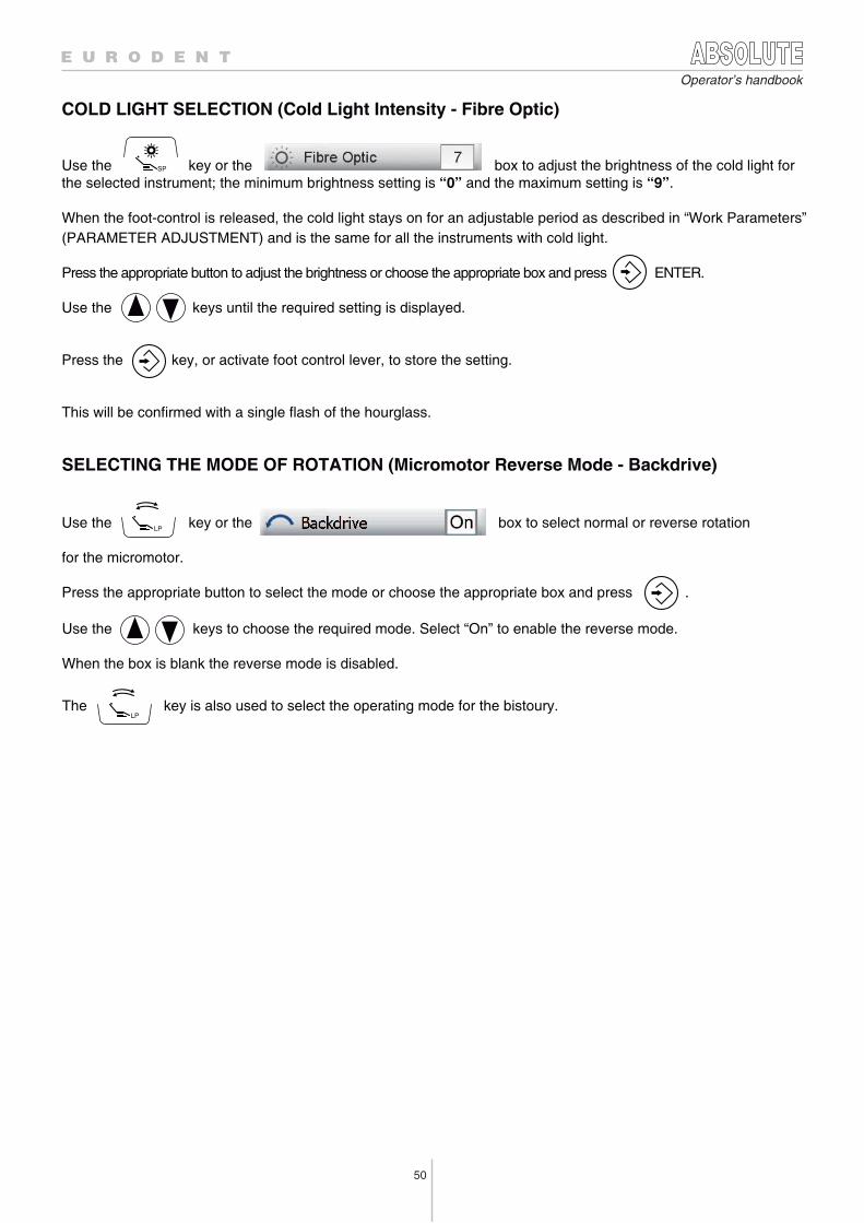
50
Operator’s handbook
COLD LIGHT SELECTION (Cold Light Intensity - Fibre Optic)
Use the key or the box to adjust the brightness of the cold light forthe selected instrument; the minimum brightness setting is “0” and the maximum setting is “9”.
When the foot-control is released, the cold light stays on for an adjustable period as described in “Work Parameters”
SELECTING THE MODE OF ROTATION (Micromotor Reverse Mode - Backdrive)
(PARAMETER ADJUSTMENT) and is the same for all the instruments with cold light.
Press the appropriate button to adjust the brightness or choose the appropriate box and press ENTER.
Use the keys until the required setting is displayed.
Press the key, or activate foot control lever, to store the setting.
This will be confirmed with a single flash of the hourglass.
Use the key or the box to select normal or reverse rotation
for the micromotor.
Press the appropriate button to select the mode or choose the appropriate box and press .
Use the keys to choose the required mode. Select “On” to enable the reverse mode.
When the box is blank the reverse mode is disabled.
The key is also used to select the operating mode for the bistoury.
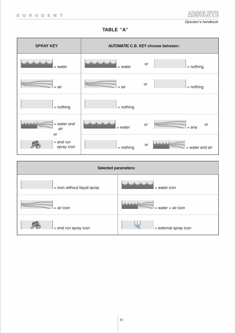
51
Operator’s handbook
TABLE “A”
SPRAY KEY AUTOMATIC C.B. KEY choose between:
= water = wateror
= nothing
= air = airor
= nothing
= nothing = nothing
= water and air = water
or = aria
or
= nothingor
= water and air
Selected parameters:
= icon without liquid spray = water icon
= air icon = water + air icon
= end run spray icon
= end run spray icon
= external spray icon
or
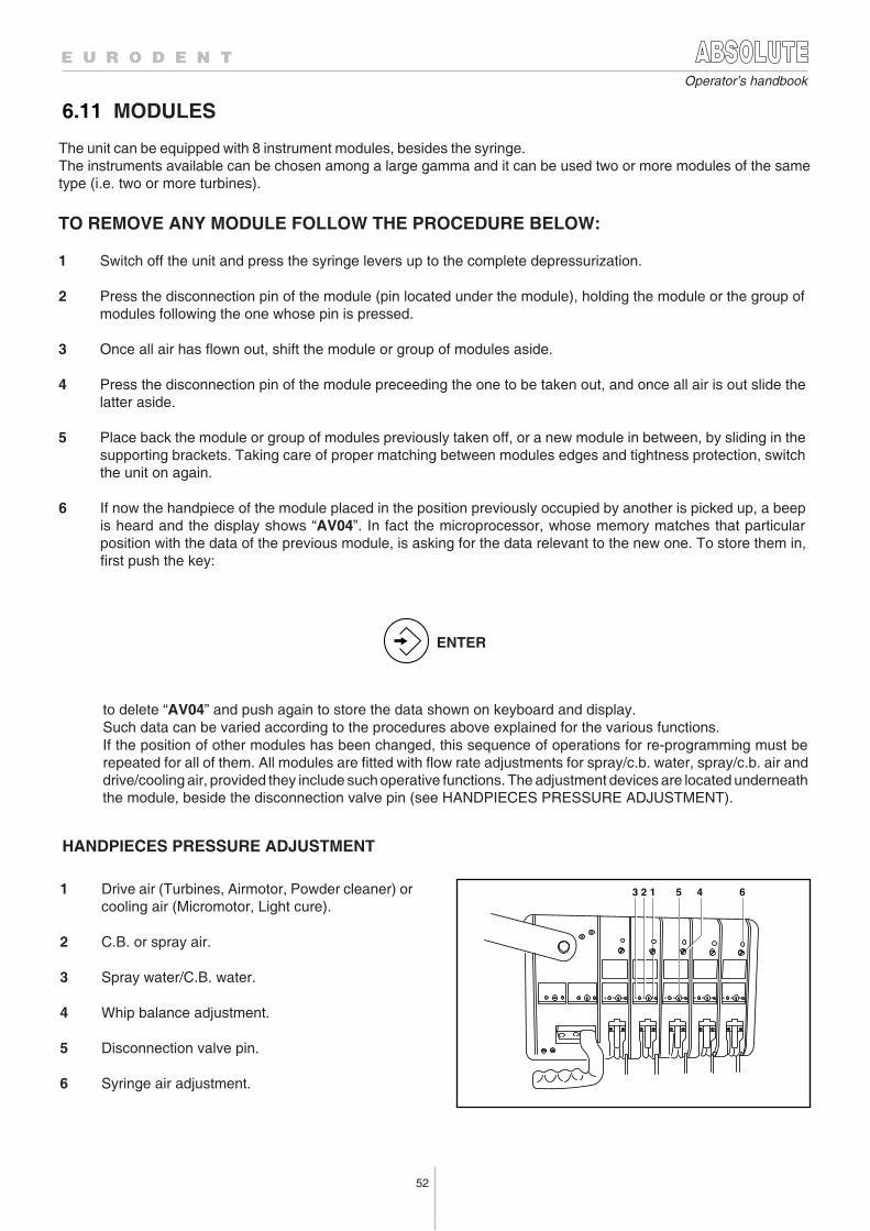
52
Operator’s handbook
HANDPIECES PRESSURE ADJUSTMENT
ENTER
6.11 MODULES
5 4 63 2 1
The unit can be equipped with 8 instrument modules, besides the syringe.The instruments available can be chosen among a large gamma and it can be used two or more modules of the sametype (i.e. two or more turbines).
TO REMOVE ANY MODULE FOLLOW THE PROCEDURE BELOW:
1 Switch off the unit and press the syringe levers up to the complete depressurization.
2 Press the disconnection pin of the module (pin located under the module), holding the module or the group ofmodules following the one whose pin is pressed.
3 Once all air has flown out, shift the module or group of modules aside.
4 Press the disconnection pin of the module preceeding the one to be taken out, and once all air is out slide thelatter aside.
5 Place back the module or group of modules previously taken off, or a new module in between, by sliding in thesupporting brackets. Taking care of proper matching between modules edges and tightness protection, switchthe unit on again.
6 If now the handpiece of the module placed in the position previously occupied by another is picked up, a beepis heard and the display shows “AV04”. In fact the microprocessor, whose memory matches that particularposition with the data of the previous module, is asking for the data relevant to the new one. To store them in,first push the key:
to delete “AV04” and push again to store the data shown on keyboard and display.Such data can be varied according to the procedures above explained for the various functions.If the position of other modules has been changed, this sequence of operations for re-programming must berepeated for all of them. All modules are fitted with flow rate adjustments for spray/c.b. water, spray/c.b. air anddrive/cooling air, provided they include such operative functions. The adjustment devices are located underneaththe module, beside the disconnection valve pin (see HANDPIECES PRESSURE ADJUSTMENT).
1 Drive air (Turbines, Airmotor, Powder cleaner) orcooling air (Micromotor, Light cure).
2 C.B. or spray air.
3 Spray water/C.B. water.
4 Whip balance adjustment.
5 Disconnection valve pin.
6 Syringe air adjustment.
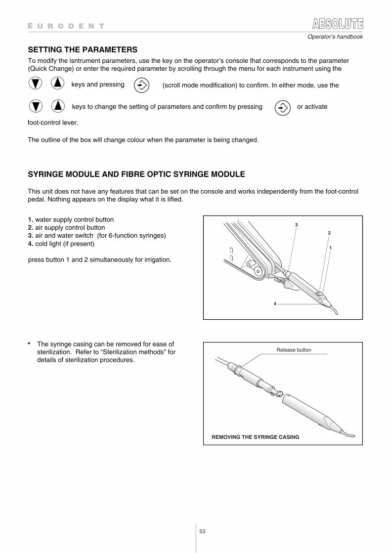
53
Operator’s handbook
SYRINGE MODULE AND FIBRE OPTIC SYRINGE MODULE
• The syringe casing can be removed for ease ofsterilization. Refer to “Sterilization methods” fordetails of sterilization procedures.
This unit does not have any features that can be set on the console and works independently from the foot-controlpedal. Nothing appears on the display what it is lifted.
REMOVING THE SYRINGE CASING
4
1
2
3
Release button
SETTING THE PARAMETERS
1. water supply control button2. air supply control button3. air and water switch (for 6-function syringes) 4. cold light (if present)
press button 1 and 2 simultaneously for irrigation.
To modify the isntrument parameters, use the key on the operator’s console that corresponds to the parameter (Quick Change) or enter the required parameter by scrolling through the menu for each instrument using the
keys and pressing (scroll mode modification) to confirm. In either mode, use the
keys to change the setting of parameters and confirm by pressing or activate
The outline of the box will change colour when the parameter is being changed.
foot-control lever.
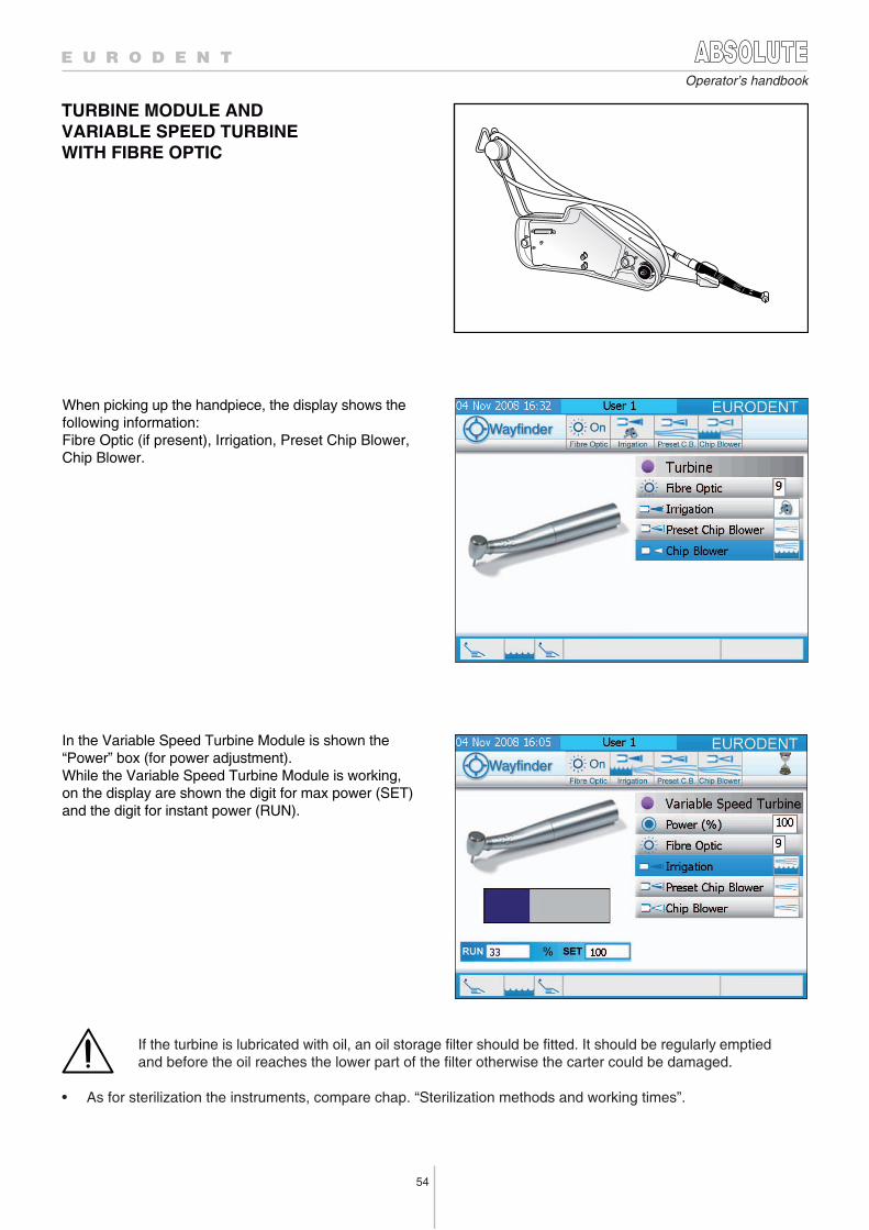
54
Operator’s handbook
TURBINE MODULE AND VARIABLE SPEED TURBINEWITH FIBRE OPTIC
If the turbine is lubricated with oil, an oil storage filter should be fitted. It should be regularly emptiedand before the oil reaches the lower part of the filter otherwise the carter could be damaged.
• As for sterilization the instruments, compare chap. “Sterilization methods and working times”.
In the Variable Speed Turbine Module is shown the“Power” box (for power adjustment). While the Variable Speed Turbine Module is working,on the display are shown the digit for max power (SET)and the digit for instant power (RUN).
When picking up the handpiece, the display shows thefollowing information:Fibre Optic (if present), Irrigation, Preset Chip Blower, Chip Blower.
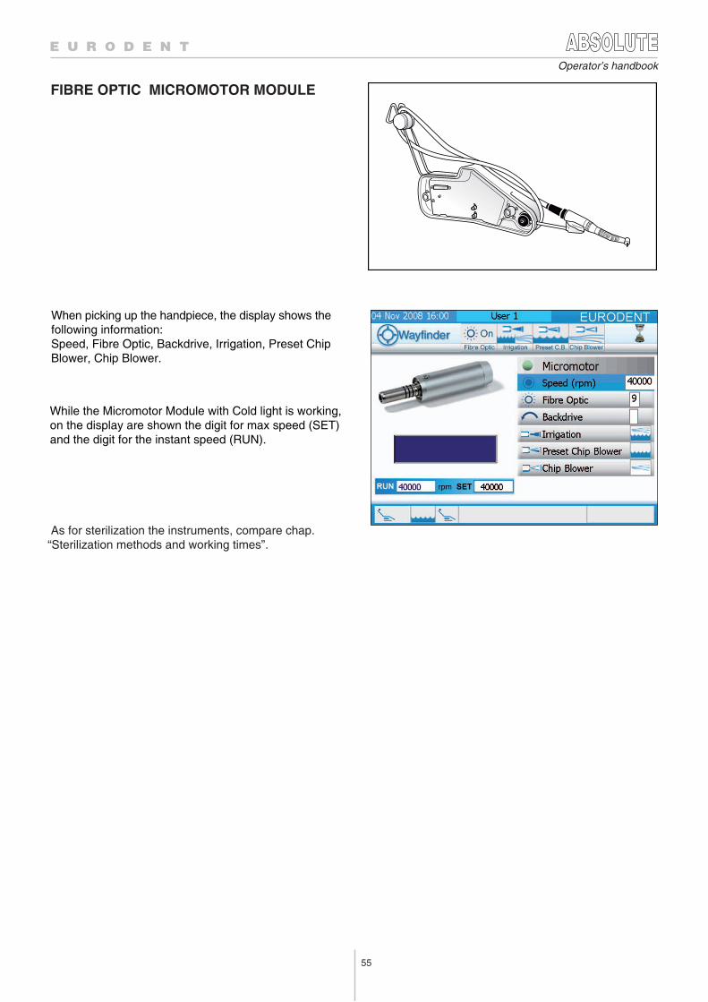
55
Operator’s handbook
FIBRE OPTIC MICROMOTOR MODULE
When picking up the handpiece, the display shows thefollowing information:Speed, Fibre Optic, Backdrive, Irrigation, Preset ChipBlower, Chip Blower.
While the Micromotor Module with Cold light is working, on the display are shown the digit for max speed (SET) and the digit for the instant speed (RUN).
As for sterilization the instruments, compare chap. “Sterilization methods and working times”.
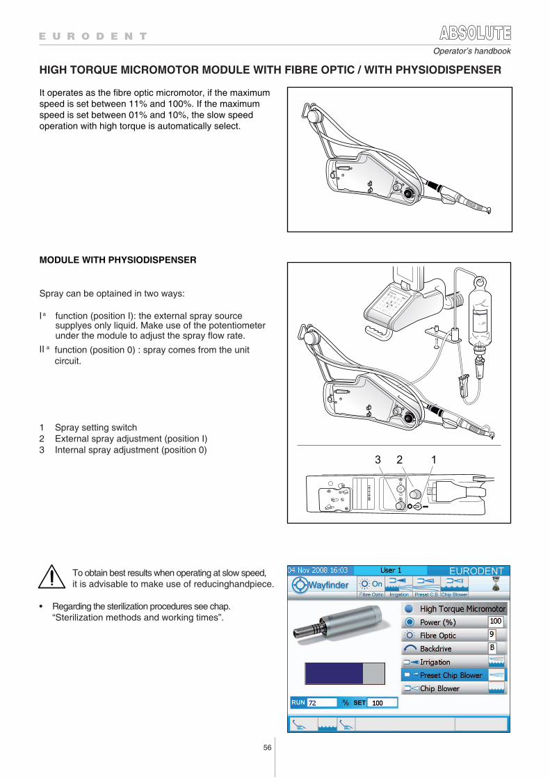
56
Operator’s handbook
It operates as the fibre optic micromotor, if the maximumspeed is set between 11% and 100%. If the maximumspeed is set between 01% and 10%, the slow speedoperation with high torque is automatically select.
MODULE WITH PHYSIODISPENSER
Spray can be optained in two ways:
I a function (position I): the external spray source supplyes only liquid. Make use of the potentiometer under the module to adjust the spray flow rate.
II a function (position 0) : spray comes from the unitcircuit.
hctiws gnittes yarpS 1 )I noitisop( tnemtsujda yarps lanretxE 2 )0 noitisop( tnemtsujda yarps lanretnI 3
To obtain best results when operating at slow speed,it is advisable to make use of reducinghandpiece.
• Regarding the sterilization procedures see chap. “Sterilization methods and working times”.
3 2 1
HIGH TORQUE MICROMOTOR MODULE WITH FIBRE OPTIC / WITH PHYSIODISPENSER
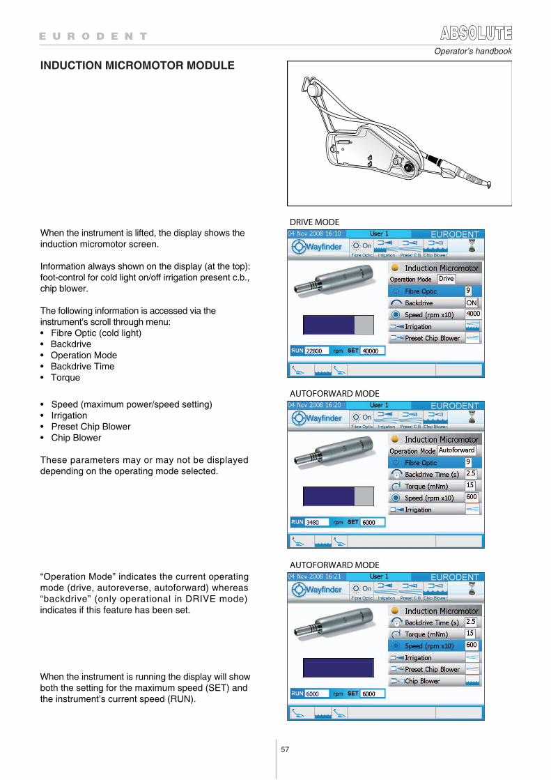
57
Operator’s handbook
INDUCTION MICROMOTOR MODULE
DRIVE MODE
AUTOFORWARD MODE
AUTOFORWARD MODE
When the instrument is lifted, the display shows theinduction micromotor screen.
Information always shown on the display (at the top):foot-control for cold light on/off irrigation present c.b.,chip blower.
The following information is accessed via the instrument’s scroll through menu:• Fibre Optic (cold light)• Backdrive• Operation Mode • Backdrive Time• Torque
• Speed (maximum power/speed setting)• Irrigation• Preset Chip Blower• Chip Blower
These parameters may or may not be displayeddepending on the operating mode selected.
“Operation Mode” indicates the current operating mode (drive, autoreverse, autoforward) whereas “backdrive” (only operational in DRIVE mode) indicates if this feature has been set.
When the instrument is running the display will show both the setting for the maximum speed (SET) andthe instrument’s current speed (RUN).
58
Operator’s handbook
The operating mode are:• Drive mode: This is indicated on the display WITH th “DRIVE” in the “Operation Mode” box. The
micromotor can operate from 100 a 40000 rpm in this mode. The maximum operating speed is set that corresponds to the position of the foot-control pedal pressed as far as it will go. The direction of rotation can be reversed using the appropiate key or the foot-control pedal or the instrument’s scroll trhough menu.
• Autoreverse Mode: This is indicated on the display with “AUTOREVERSE” in the “Operation Mode” box. The micromotor can operate from 100 to 6000 rpm in this mode. The maximum operating speed is set that is less than 6000 rpm and corresponds to the position of the foot-control pedal pressed as far as it will go. Thetorque setting (between 3 e 30 mNm) can also be set. When the setting is reached the micromotor will start turning in the opposite direction. The fiber optic light signals the reversal by starting to flash. Release the foot-control and start the micromotor again. It will resume operation with clockwise rotation until it reaches the torque setting again and reverse the direction of rotation. It is not possible to reverse the direction of rotation using the appropiate key or the foot-control pedal or the instrument’s scroll-through menu in this mode.
• Autoforward mode: This is indicated on the display with “AUTOFORWARD” in the “Operation Mode” box. box. It works like autoreverse mode but a pause can also be set between 0,5 e 3,5 s. When it reaches the torque setting, the micromotor starts turning in the opposite direction until it reaches zero torque. It waits for the end of the set pause and then reverse the direction of rotation by turning clockwise again. Again the fiber optic light signals the reversal by starting to flash. It is not possible to reverse the direction of rotation using the appropiate key or the foot-control pedal or the instrument’s scroll-through menu.
4
OPERATING MODE SETTINGS
Use the instrument’s scroll-through menu to change the operating mode settings. Enter the “Operation Mode” box andpress ENTER to access the various settings. The outline of the “Operation Mode” box will change colour.
Press the keys to alter the operating mode.
Store the new setting using the ENTER key or operating foot-control lever.
SETTING THE MAXIMUM SPEED
Change the speed settings by pressing the key or using the instrument’s scroll-through menu to select the
“Speed” box and press
This accesses the speed setting and the outline of the “Speed” box will change colour.
Change the setting using the keys.
Note, this setting will not reflected the true speed if there is a reduction or multiplying handle and the operator should remember to multiply or divide it by the reduction or multiplication ratio..
Press the key to store the setting or operating foot-control lever.
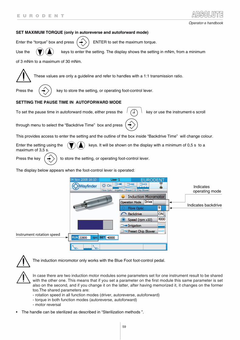
59
Operator-s handbook
Indicates backdrive
Indicatesoperating mode
Instrument rotation speed
The induction micromotor only works with the Blue Foot foot-control pedal.
SET MAXIMUM TORQUE (only in autoreverse and autoforward mode)
Enter the “torque” box and press ENTER to set the maximum torque.
Use the keys to enter the setting. The display shows the setting in mNm, from a minimum
of 3 mNm to a maximum of 30 mNm.
These values are only a guideline and refer to handles with a 1:1 transmission ratio.
Press the key to store the setting, or operating foot-control lever.
SETTING THE PAUSE TIME IN AUTOFORWARD MODE
To set the pause time in autoforward mode, either press the key or use the instrument-s scroll
through menu to select the “Backdrive Time” box and press
This provides access to enter the setting and the outline of the box inside “Backdrive Time” will change colour.
Enter the setting using the keys. It will be shown on the display with a minimum of 0,5 s to amaximum of 3,5 s.
Press the key to store the setting, or operating foot-control lever.
The display below appears when the foot-control lever is operated:
• The handle can be sterilized as described in “Sterilization methods ”.
In case there are two induction motor modules some parameters set for one instrument result to be sharedwith the other one. This means that if you set a parameter on the first module this same parameter is setalso on the second, and if you change it on the latter, after having memorized it, it changes on the formertoo.The shared parameters are:- rotation speed in all function modes (driver, autoreverse, autoforward) - torque in both function modes (autoreverse, autoforward) - motor reversal
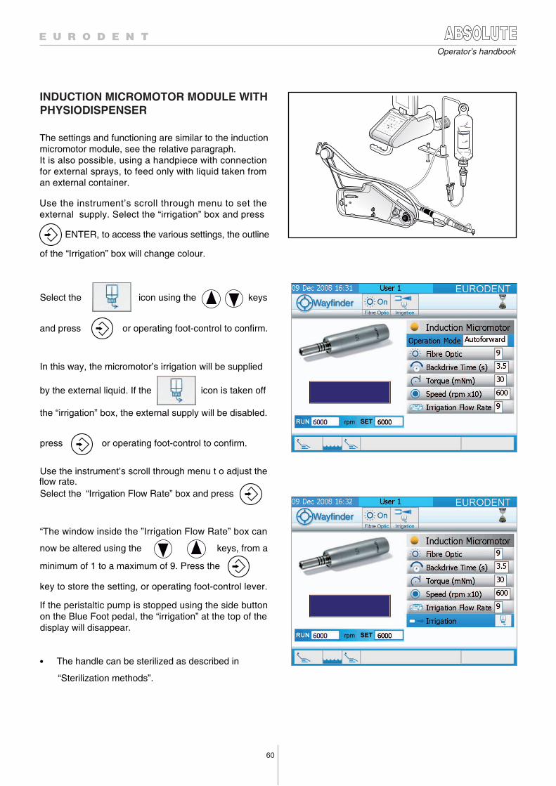
60
Operator’s handbook
INDUCTION MICROMOTOR MODULE WITH PHYSIODISPENSER
The settings and functioning are similar to the inductionmicromotor module, see the relative paragraph.It is also possible, using a handpiece with connectionfor external sprays, to feed only with liquid taken froman external container.
Use the instrument’s scroll through menu to set theexternal supply. Select the “irrigation” box and press ENTER, to access the various settings, the outline
of the “Irrigation” box will change colour.
Select the icon using the keys
and press or operating foot-control to confirm.
In this way, the micromotor’s irrigation will be supplied
by the external liquid. If the icon is taken off
the “irrigation” box, the external supply will be disabled.
press or operating foot-control to confirm.
Use the instrument’s scroll through menu t o adjust the
Select the “Irrigation Flow Rate” box and press
“The window inside the ”Irrigation Flow Rate” box can
now be altered using the keys, from a
minimum of 1 to a maximum of 9. Press the
key to store the setting, or operating foot-control lever.
If the peristaltic pump is stopped using the side buttonon the Blue Foot pedal, the “irrigation” at the top of thedisplay will disappear.
• The handle can be sterilized as described in
flow rate.
“Sterilization methods”.
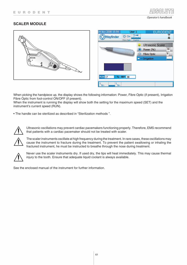
61
When picking the handpiece up, the display shows the following information: Power, Fibre Optic (if present), IrrigationFibre Optic from foot-control ON/OFF (if present).When the instrument is running the display will show both the setting for the maximum speed (SET) and theinstrument’s current speed (RUN).
• The handle can be sterilized as described in “Sterilization methods ”.
Ultrasonic oscillations may prevent cardiac pacemakers functioning properly. Therefore, EMS recommendthat patients with a cardiac pacemaker should not be treated with scaler.
The scaler instruments oscillate at high frequency during the treatment. In rare cases, these oscillations maycause the instrument to fracture during the treatment. To prevent the patient swallowing or inhaling thefractured instrument, he must be instructed to breathe through the nose during treatment.
Never use the scaler instruments dry. If used dry, the tips will heat immediately. This may cause thermalinjury to the tooth. Ensure that adequate liquid coolant is always available.
See the enclosed manual of the instrument for further information.
Operator’s handbook
SCALER MODULE
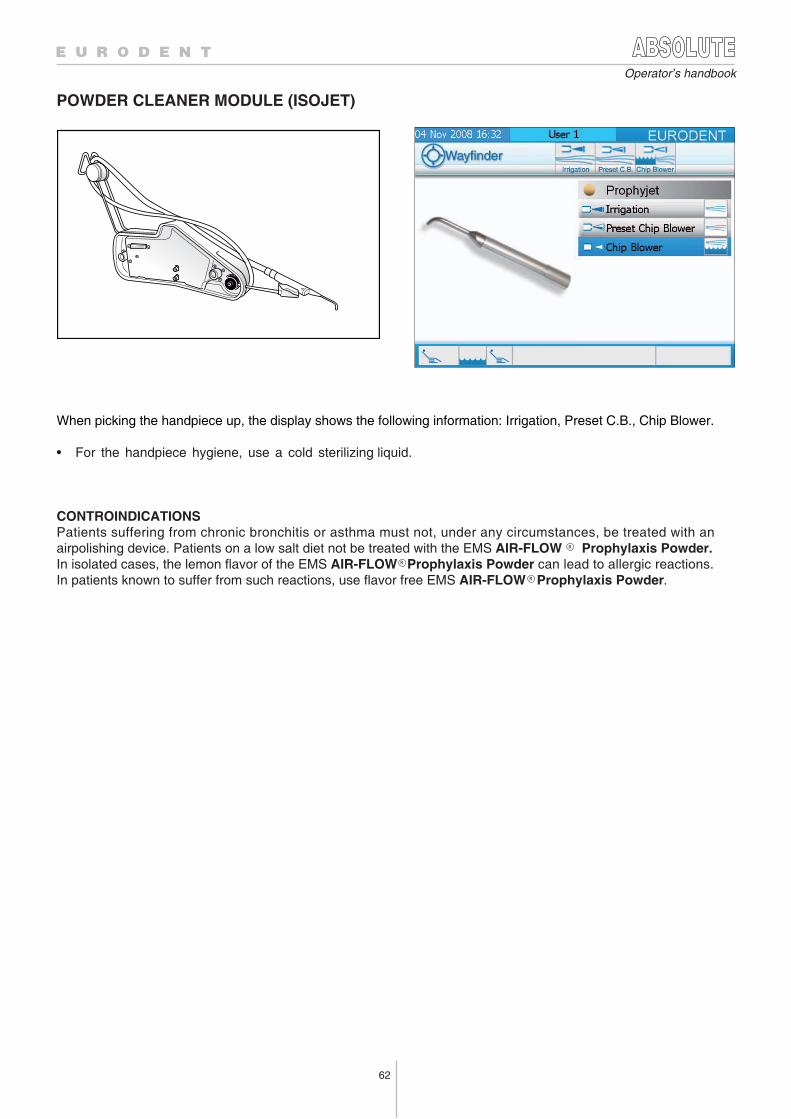
62
Operator’s handbook
POWDER CLEANER MODULE (ISOJET)
When picking the handpiece up, the display shows the following information: Irrigation, Preset C.B., Chip Blower.
• For the handpiece hygiene, use a cold sterilizing liquid.
CONTROINDICATIONSPatients suffering from chronic bronchitis or asthma must not, under any circumstances, be treated with anairpolishing device. Patients on a low salt diet not be treated with the EMS AIR-FLOW Prophylaxis Powder.In isolated cases, the lemon flavor of the EMS AIR-FLOW Prophylaxis Powder can lead to allergic reactions.In patients known to suffer from such reactions, use flavor free EMS AIR-FLOW Prophylaxis Powder.
R
R
R
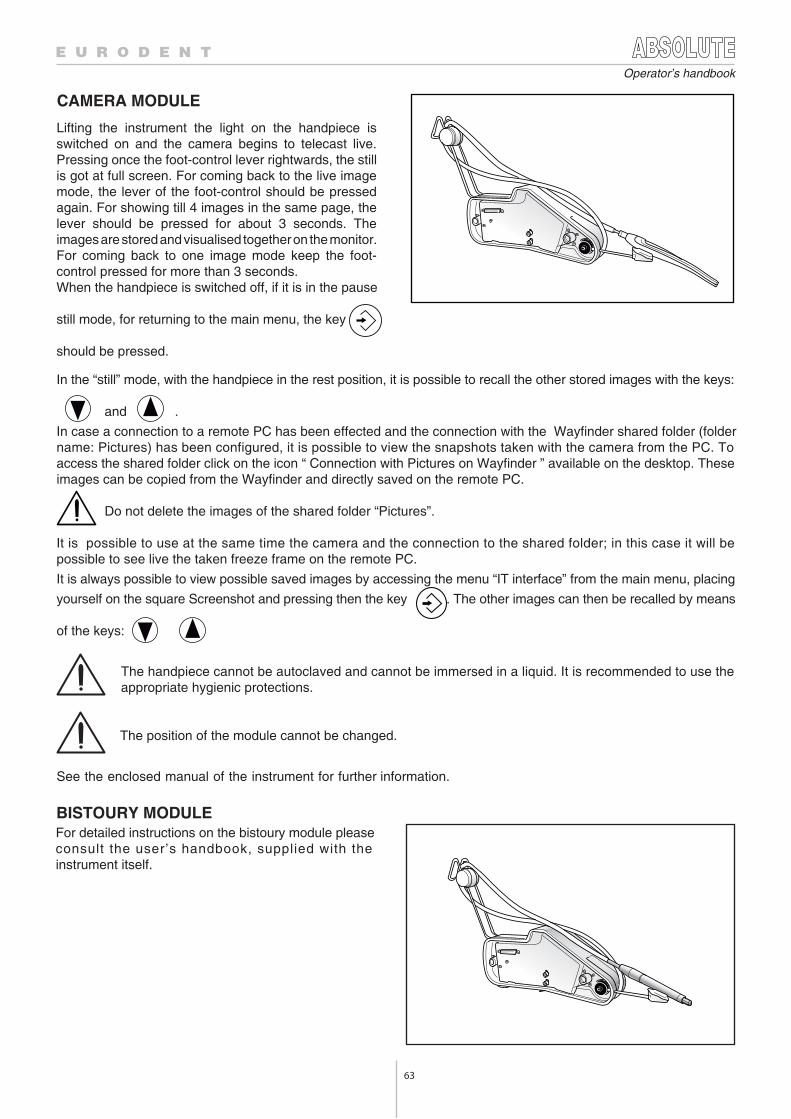
63
Operator’s handbook
CAMERA MODULE
BISTOURY MODULEFor detailed instructions on the bistoury module pleaseconsult the user’s handbook, supplied with theinstrument itself.
Lifting the instrument the light on the handpiece isswitched on and the camera begins to telecast live.Pressing once the foot-control lever rightwards, the stillis got at full screen. For coming back to the live imagemode, the lever of the foot-control should be pressedagain. For showing till 4 images in the same page, thelever should be pressed for about 3 seconds. Theimages are stored and visualised together on the monitor.For coming back to one image mode keep the foot-control pressed for more than 3 seconds.When the handpiece is switched off, if it is in the pause
still mode, for returning to the main menu, the key
should be pressed.
The handpiece cannot be autoclaved and cannot be immersed in a liquid. It is recommended to use theappropriate hygienic protections.
The position of the module cannot be changed.
See the enclosed manual of the instrument for further information.
In the “still” mode, with the handpiece in the rest position, it is possible to recall the other stored images with the keys:
and .
In case a connection to a remote PC has been effected and the connection with the Wayfinder shared folder (foldername: Pictures) has been configured, it is possible to view the snapshots taken with the camera from the PC. Toaccess the shared folder click on the icon “ Connection with Pictures on Wayfinder ” available on the desktop. Theseimages can be copied from the Wayfinder and directly saved on the remote PC. Do not delete the images of the shared folder “Pictures”.
It is possible to use at the same time the camera and the connection to the shared folder; in this case it will bepossible to see live the taken freeze frame on the remote PC.
It is always possible to view possible saved images by accessing the menu “IT interface” from the main menu, placing
yourself on the square Screenshot and pressing then the key . The other images can then be recalled by means
of the keys:
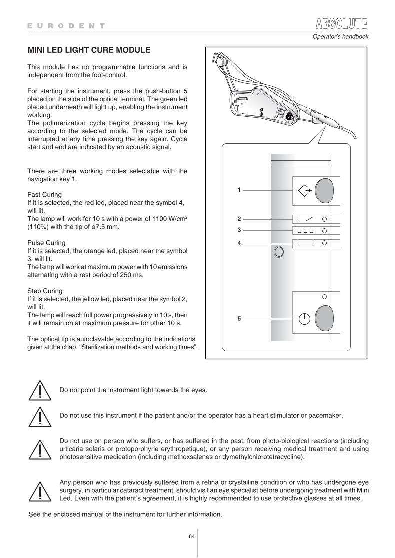
64
Operator’s handbook
MINI LED LIGHT CURE MODULE
1
2
3
4
5
This module has no programmable functions and isindependent from the foot-control.
For starting the instrument, press the push-button 5placed on the side of the optical terminal. The green ledplaced underneath will light up, enabling the instrumentworking.The polimerization cycle begins pressing the keyaccording to the selected mode. The cycle can beinterrupted at any time pressing the key again. Cyclestart and end are indicated by an acoustic signal.
There are three working modes selectable with thenavigation key 1.
Fast CuringIf it is selected, the red led, placed near the symbol 4,will lit.The lamp will work for 10 s with a power of 1100 W/cm2
(110%) with the tip of ø7.5 mm.
Pulse CuringIf it is selected, the orange led, placed near the symbol3, will lit.The lamp will work at maximum power with 10 emissionsalternating with a rest period of 250 ms.
Step CuringIf it is selected, the jellow led, placed near the symbol 2,will lit.The lamp will reach full power progressively in 10 s, thenit will remain on at maximum pressure for other 10 s.
The optical tip is autoclavable according to the indicationsgiven at the chap. “Sterilization methods and working times”.
Do not point the instrument light towards the eyes.
Do not use this instrument if the patient and/or the operator has a heart stimulator or pacemaker.
Do not use on person who suffers, or has suffered in the past, from photo-biological reactions (includingurticaria solaris or protoporphyrie erythropetique), or any person receiving medical treatment and usingphotosensitive medication (including methoxsalenes or dymethylchlorotetracycline).
Any person who has previously suffered from a retina or crystalline condition or who has undergone eyesurgery, in particular cataract treatment, should visit an eye specialist before undergoing treatment with MiniLed. Even with the patient’s agreement, it is highly recommended to use protective glasses at all times.
See the enclosed manual of the instrument for further information.
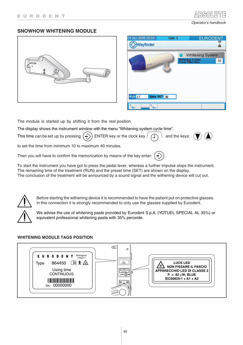
65
Operator’s handbook
SNOWHOW WHITENING MODULE
Before starting the withening device it is recommended to have the patient put on protective glasses. In this connection it is strongly recommended to only use the glasses supplied by Eurodent.
We advise the use of whitening paste provided by Eurodent S.p.A. (YOTUEL SPECIAL AL 35%) or equivalent professional whitening paste with 35% peroxide.
WHITENING MODULE TAGS POSITION
BolognaITALY
Type 864450
Using timeCONTINUOS
SN: 00000000
BolognaITALY
Type 864450
Using timeCONTINUOUS
SN: 00000000
The module is started up by shifting it from the rest position.
The display shows the instrument window with the menu “Whitening system cycle time”.
This time can be set up by pressing ENTER key or the clock key and the keys:
to set the time from minimum 10 to maximum 40 minutes.
Then you will have to confirm the memorization by means of the key enter: .
To start the instrument you have got to press the pedal lever, whereas a further impulse stops the instrument.The remaining time of the treatment (RUN) and the preset time (SET) are shown on the display.The conclusion of the treatment will be announced by a sound signal and the withening device will cut out.
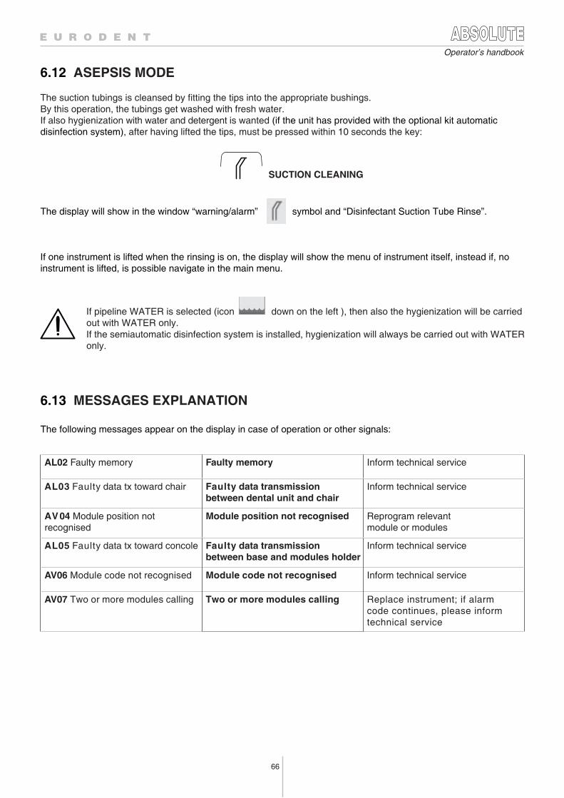
66
Operator’s handbook
6.12 ASEPSIS MODE
SUCTION CLEANING
If pipeline WATER is selected (icon down on the left ), then also the hygienization will be carriedout with WATER only.
If the semiautomatic disinfection system is installed, hygienization will always be carried out with WATERonly.
6.13 MESSAGES EXPLANATION
The following messages appear on the display in case of operation or other signals:
AL02 Faulty memory Faulty memory Inform technical service
AL03 Faulty data tx toward chair Faulty data transmission between dental unit and chair
Inform technical service
AV04 Module position not recognised
Module position not recognised Reprogram relevantmodule or modules
AL05 Faulty data tx toward concole Faulty data transmission between base and modules holder
Inform technical service
AV06 Module code not recognised Module code not recognised Inform technical service
AV07 Two or more modules calling Two or more modules calling Replace instrument; if alarmcode continues, please informtechnical service
The suction tubings is cleansed by fitting the tips into the appropriate bushings.By this operation, the tubings get washed with fresh water.If also hygienization with water and detergent is wanted (if the unit has provided with the optional kit automaticdisinfection system), after having lifted the tips, must be pressed within 10 seconds the key:
The display will show in the window “warning/alarm” symbol and “Disinfectant Suction Tube Rinse”.
If one instrument is lifted when the rinsing is on, the display will show the menu of instrument itself, instead if, noinstrument is lifted, is possible navigate in the main menu.
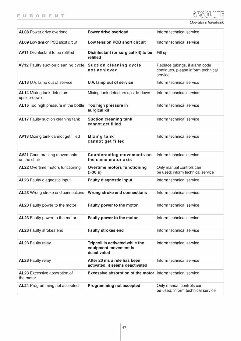
67
Operator’s handbook
AV11 Disinfectant to be refilled Disinfectant (or surgical kit) to berefilled
Fill up
AV12 Faulty suction cleaning cycle Suction cleaning cyclenot achieved
Replace tubings, if alarm code continues, please inform technicalservice
AL13 U.V. lamp out of service U.V. lamp out of service Inform technical service
AL14 Mixing tank detectors upside-down
Mixing tank detectors upside-down Inform technical service
AL15 Too high pressure in the bottle Too high pressure insurgical kit
Inform technical service
AL17 Faulty suction cleaning tank Suction cleaning tankcannot get filled
Inform technical service
AV18 Mixing tank cannot get filled Mixing tankcannot get fil led
Inform technical service
AV21 Counteracting movementson the chair
Counteracting movements onthe same motor axis
Inform technical service
AL22 Overtime motors functioning Overtime motors functioning(>30 s)
Only manual controls canbe used; inform technical service
AL23 Faulty diagnostic input Faulty diagnostic input Inform technical service
AL23 Wrong stroke end connections Wrong stroke end connections Inform technical service
AL23 Faulty power to the motor Faulty power to the motor Inform technical service
AL23 Faulty power to the motor Faulty power to the motor Inform technical service
AL23 Faulty strokes end Faulty strokes end Inform technical service
AL23 Faulty relay Tripcoil is activated while theequipment movement isdeactivated
Inform technical service
AL23 Faulty relay After 20 ms a relè has beenactivated, it seems deactivated
Inform technical service
AL23 Excessive absorption ofthe motor
Excessive absorption of the motor Inform technical service
AL24 Programming not accepted Programming not accepted Only manual controls canbe used; inform technical service
AL08 Power drive overload Power drive overload Inform technical service
AL09 Low tension PCB short circuit Low tension PCB short circuit Inform technical service
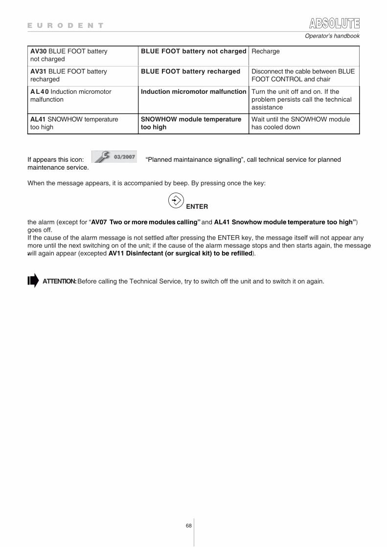
68
Operator’s handbook
AL40 Induction micromotormalfunction
Induction micromotor malfunction Turn the unit off and on. If the problem persists call the technicalassistance
AL41 SNOWHOW temperaturetoo high
SNOWHOW module temperaturetoo high
Wait until the SNOWHOW modulehas cooled down
AV30 BLUE FOOT batterynot charged
BLUE FOOT battery not charged Recharge
AV31 BLUE FOOT batteryrecharged
BLUE FOOT battery recharged Disconnect the cable between BLUEFOOT CONTROL and chair
If appears this icon: “Planned maintainance signalling”, call technical service for plannedmaintenance service.
When the message appears, it is accompanied by beep. By pressing once the key:
the alarm (except for “AV07 Two or more modules calling” and AL41 Snowhow module temperature too high”)goes off.If the cause of the alarm message is not settled after pressing the ENTER key, the message itself will not appear anymore until the next switching on of the unit; if the cause of the alarm message stops and then starts again, the messagewill again appear (excepted AV11 Disinfectant (or surgical kit) to be refilled).
ENTER
“
ATTENTION: Before calling the Technical Service, try to switch off the unit and to switch it on again.
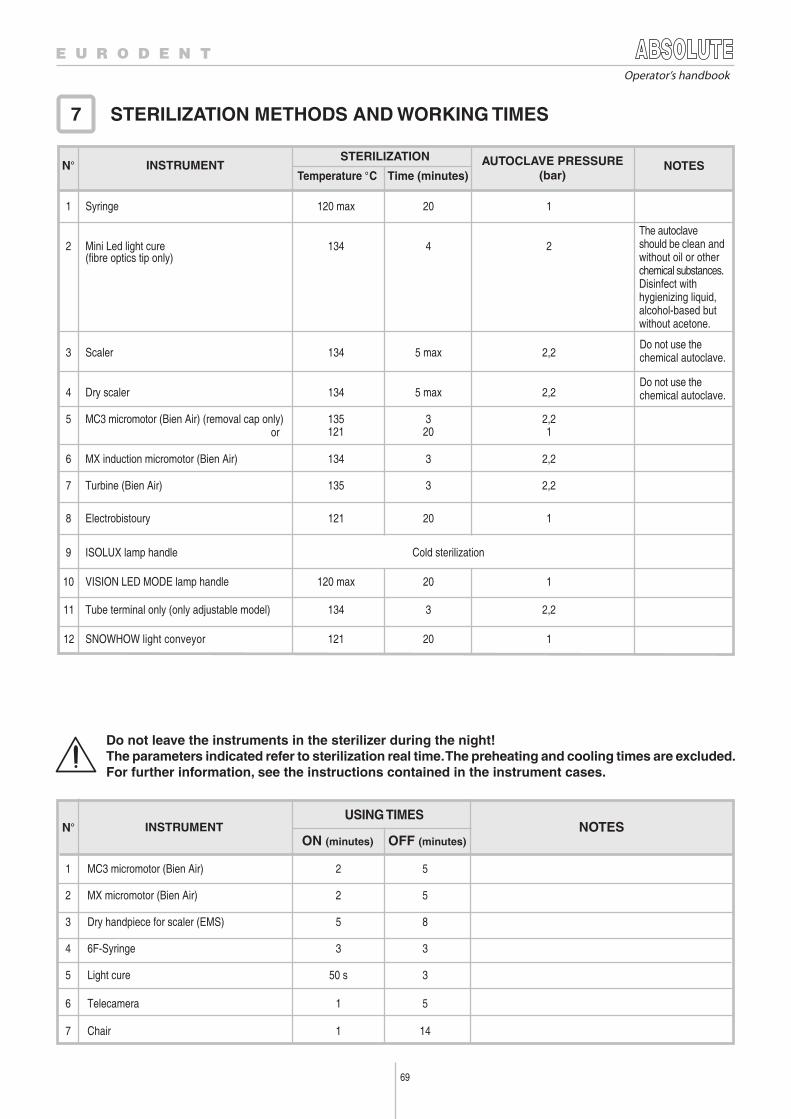
69
Operator’s handbook
STERILIZATION METHODS AND WORKING TIMES 7
Time (minutes)Temperature °C
STERILIZATION AUTOCLAVE PRESSURE(bar)
INSTRUMENT NOTESN°
USING TIMESINSTRUMENT NOTES
ON (minutes) OFF (minutes)
Do not leave the instruments in the sterilizer during the night!The parameters indicated refer to sterilization real time. The preheating and cooling times are excluded.For further information, see the instructions contained in the instrument cases.
52MC3 micromotor (Bien Air)1
52MX micromotor (Bien Air)2
85Dry handpiece for scaler (EMS)3
336F-Syringe4
350 sLight cure5
51Telecamera6
1417 riahC
N°
120120 maxSyringe1
24134Mini Led light cure(fibre optics tip only)
2
2,2 5 max134Scaler3
2,25 max134Dry scaler4
5 MC3 micromotor (Bien Air) (removal cap only) or
2,23135120121
120121
2,23134MX induction micromotor (Bien Air)6
2,23135Turbine (Bien Air)7
8 Electrobistoury
Cold sterilizationISOLUX lamp handle9
120120 maxVISION LED MODE lamp handle10
2,23134Tube terminal only (only adjustable model)11
120121SNOWHOW light conveyor12
The autoclaveshould be clean andwithout oil or otherchemical substances.Disinfect withhygienizing liquid,alcohol-based butwithout acetone.
Do not use thechemical autoclave.
Do not use thechemical autoclave.
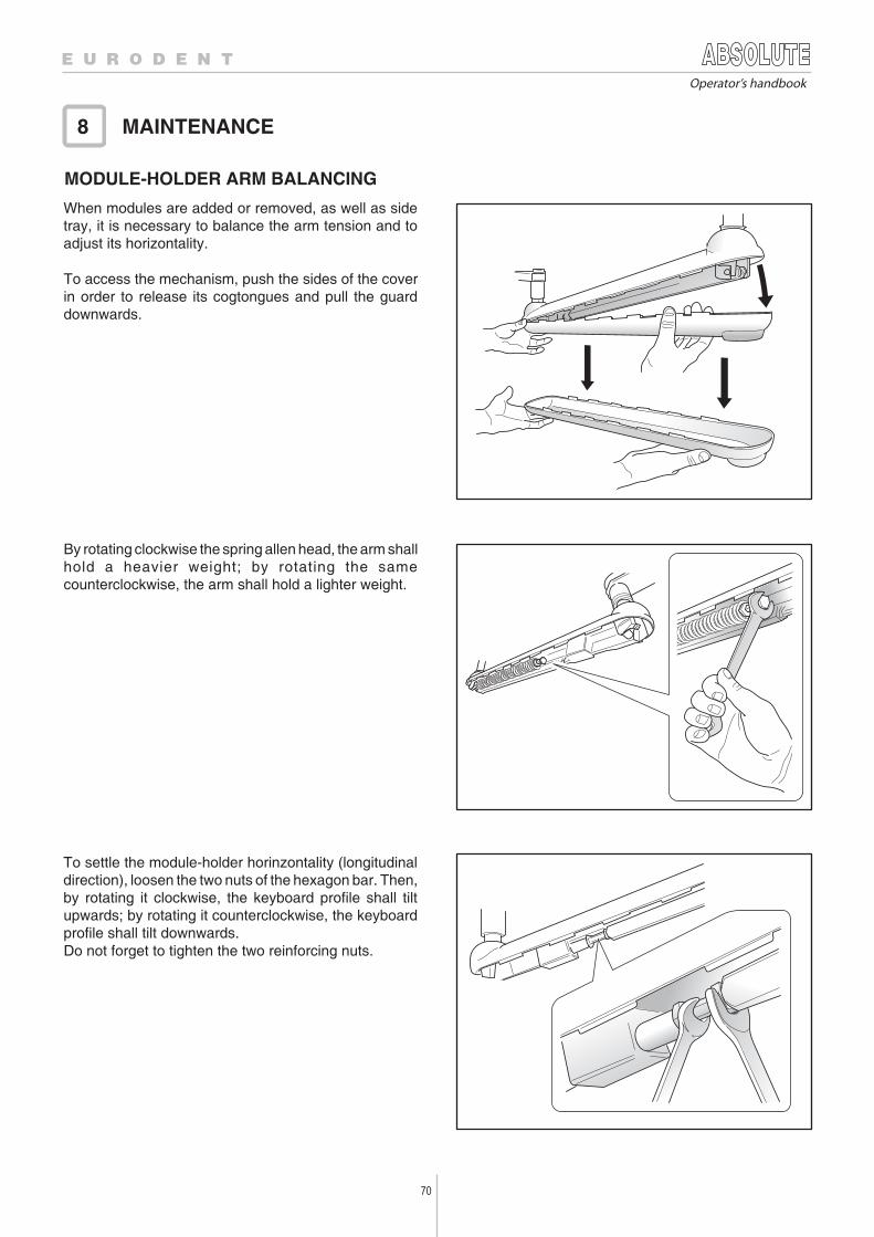
70
Operator’s handbook
To settle the module-holder horinzontality (longitudinaldirection), loosen the two nuts of the hexagon bar. Then,by rotating it clockwise, the keyboard profile shall tiltupwards; by rotating it counterclockwise, the keyboardprofile shall tilt downwards.Do not forget to tighten the two reinforcing nuts.
By rotating clockwise the spring allen head, the arm shallhold a heavier weight; by rotating the samecounterclockwise, the arm shall hold a lighter weight.
When modules are added or removed, as well as sidetray, it is necessary to balance the arm tension and toadjust its horizontality.
To access the mechanism, push the sides of the coverin order to release its cogtongues and pull the guarddownwards.
MODULE-HOLDER ARM BALANCING
MAINTENANCE8
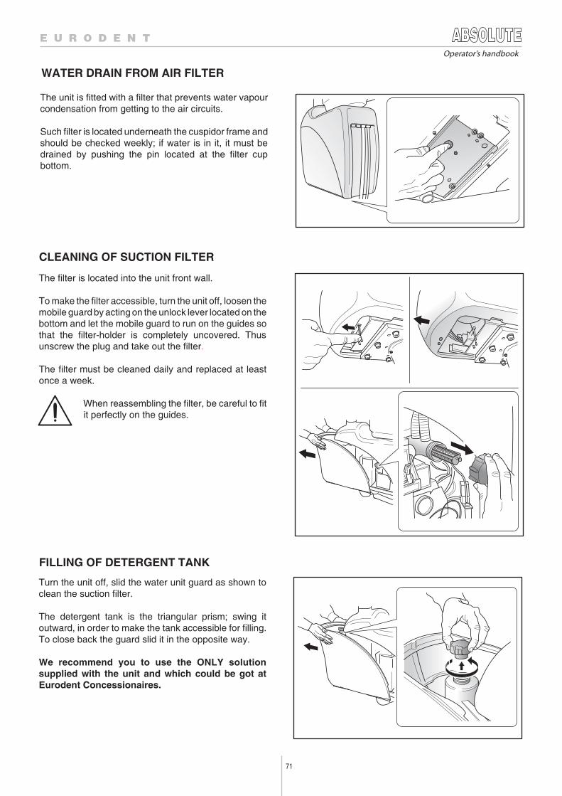
71
Operator’s handbook
WATER DRAIN FROM AIR FILTER
The unit is fitted with a filter that prevents water vapourcondensation from getting to the air circuits.
Such filter is located underneath the cuspidor frame andshould be checked weekly; if water is in it, it must bedrained by pushing the pin located at the filter cupbottom.
CLEANING OF SUCTION FILTER
The filter is located into the unit front wall.
To make the filter accessible, turn the unit off, loosen themobile guard by acting on the unlock lever located on thebottom and let the mobile guard to run on the guides sothat the filter-holder is completely uncovered. Thusunscrew the plug and take out the filter.
The filter must be cleaned daily and replaced at leastonce a week.
When reassembling the filter, be careful to fitit perfectly on the guides.
FILLING OF DETERGENT TANK
Turn the unit off, slid the water unit guard as shown toclean the suction filter.
The detergent tank is the triangular prism; swing itoutward, in order to make the tank accessible for filling.To close back the guard slid it in the opposite way.
We recommend you to use the ONLY solutionsupplied with the unit and which could be got atEurodent Concessionaires.
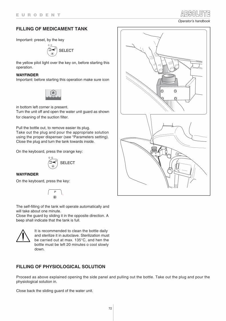
72
Operator’s handbook
FILLING OF MEDICAMENT TANK
Important: preset, by the key
the yellow pilot light over the key on, before starting thisoperation.
SELECT
WAYFINDERImportant: before starting this operation make sure icon
in bottom left corner is present.Turn the unit off and open the water unit guard as shownfor cleaning of the suction filter.
Pull the bottle out, to remove easier its plug.Take out the plug and pour the appropriate solutionusing the proper dispenser (see “Parameters setting). Close the plug and turn the tank towards inside.
On the keyboard, press the orange key:
SELECT
WAYFINDER
On the keyboard, press the key:
P
.
The self-filling of the tank will operate automatically andwill take about one minute.Close the guard by sliding it in the opposite direction. Abeep shall indicate that the tank is full.
It is recommended to clean the bottle daily and sterilize it in autoclave. Sterilization must be carried out at max. 135°C, and hen thebottle must be left 20 minutes o cool slowly down.
FILLING OF PHYSIOLOGICAL SOLUTION
Proceed as above explained opening the side panel and pulling out the bottle. Take out the plug and pour thephysiological solution in.
Close back the sliding guard of the water unit.
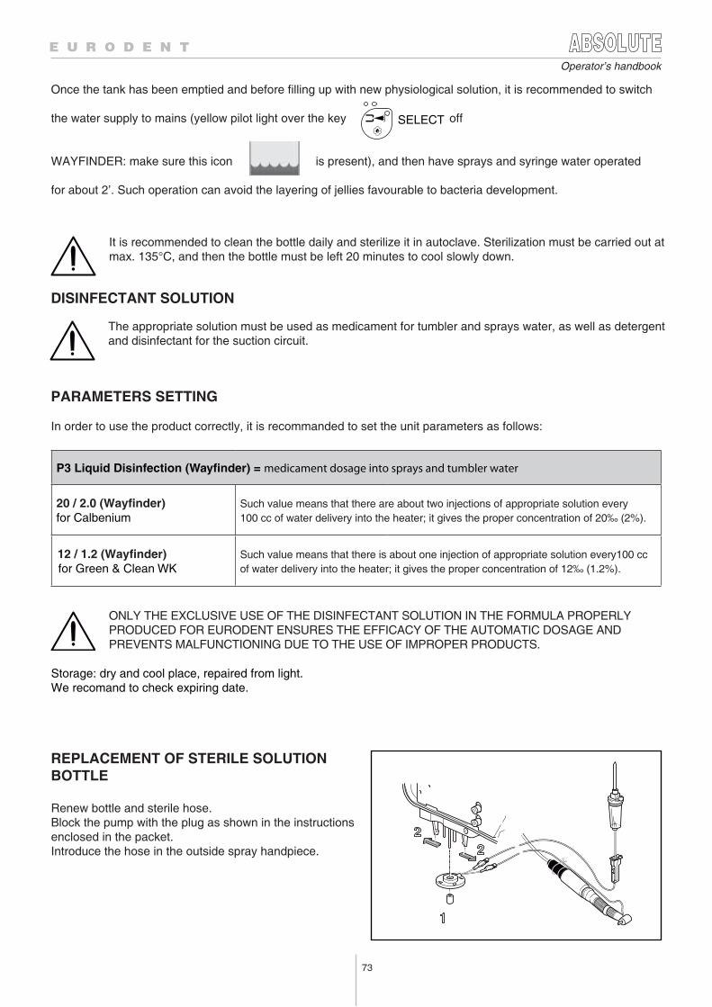
73
Operator’s handbook
REPLACEMENT OF STERILE SOLUTIONBOTTLE
Renew bottle and sterile hose.Block the pump with the plug as shown in the instructionsenclosed in the packet.Introduce the hose in the outside spray handpiece.
ONLY THE EXCLUSIVE USE OF THE DISINFECTANT SOLUTION IN THE FORMULA PROPERLYPRODUCED FOR EURODENT ENSURES THE EFFICACY OF THE AUTOMATIC DOSAGE ANDPREVENTS MALFUNCTIONING DUE TO THE USE OF IMPROPER PRODUCTS.
Storage: dry and cool place, repaired from light.We recomand to check expiring date.
P3 Liquid Disinfection (Way nder) = medicament dosage into sprays and tumbler water
20 / 2.0 (Wayfinder)for Calbenium
Such value means that there are about two injections of appropriate solution every100 cc of water delivery into the heater; it gives the proper concentration of 20‰ (2%).
12 / 1.2 (Wayfinder) for Green & Clean WK
Such value means that there is about one injection of appropriate solution every100 ccof water delivery into the heater; it gives the proper concentration of 12‰ (1.2%).
Once the tank has been emptied and before filling up with new physiological solution, it is recommended to switch
the water supply to mains (yellow pilot light over the key off
WAYFINDER: make sure this icon is present), and then have sprays and syringe water operated
for about 2’. Such operation can avoid the layering of jellies favourable to bacteria development.
SELECT
It is recommended to clean the bottle daily and sterilize it in autoclave. Sterilization must be carried out atmax. 135°C, and then the bottle must be left 20 minutes to cool slowly down.
DISINFECTANT SOLUTION
The appropriate solution must be used as medicament for tumbler and sprays water, as well as detergentand disinfectant for the suction circuit.
PARAMETERS SETTING
In order to use the product correctly, it is recommanded to set the unit parameters as follows:
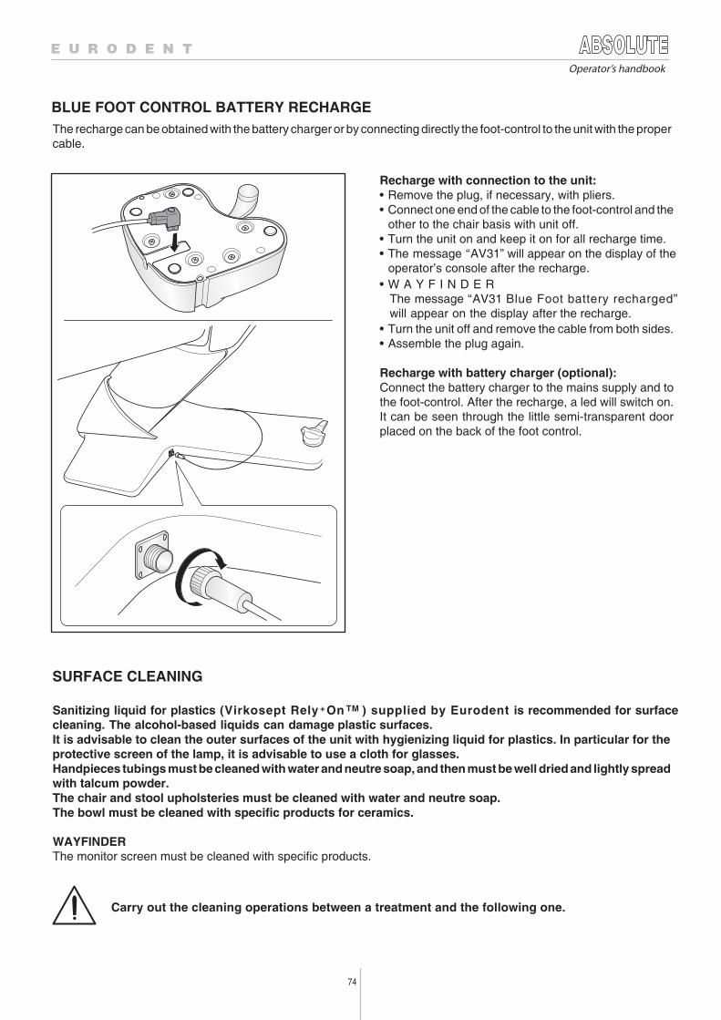
74
Operator’s handbook
SURFACE CLEANING
Sanitizing liquid for plastics (Virkosept Rely On ) supplied by Eurodent is recommended for surfacecleaning. The alcohol-based liquids can damage plastic surfaces.It is advisable to clean the outer surfaces of the unit with hygienizing liquid for plastics. In particular for theprotective screen of the lamp, it is advisable to use a cloth for glasses.Handpieces tubings must be cleaned with water and neutre soap, and then must be well dried and lightly spreadwith talcum powder.The chair and stool upholsteries must be cleaned with water and neutre soap.The bowl must be cleaned with specific products for ceramics.
WAYFINDERThe monitor screen must be cleaned with specific products.
Carry out the cleaning operations between a treatment and the following one.
BLUE FOOT CONTROL BATTERY RECHARGEThe recharge can be obtained with the battery charger or by connecting directly the foot-control to the unit with the propercable.
Recharge with connection to the unit:• Remove the plug, if necessary, with pliers.• Connect one end of the cable to the foot-control and the
other to the chair basis with unit off.• Turn the unit on and keep it on for all recharge time.• The message “AV31” will appear on the display of the
operator’s console after the recharge.• W A Y F I N D E R The message “AV31 Blue Foot battery recharged” will appear on the display after the recharge.• Turn the unit off and remove the cable from both sides.• Assemble the plug again.
Recharge with battery charger (optional):Connect the battery charger to the mains supply and tothe foot-control. After the recharge, a led will switch on.It can be seen through the little semi-transparent doorplaced on the back of the foot control.
+ TM
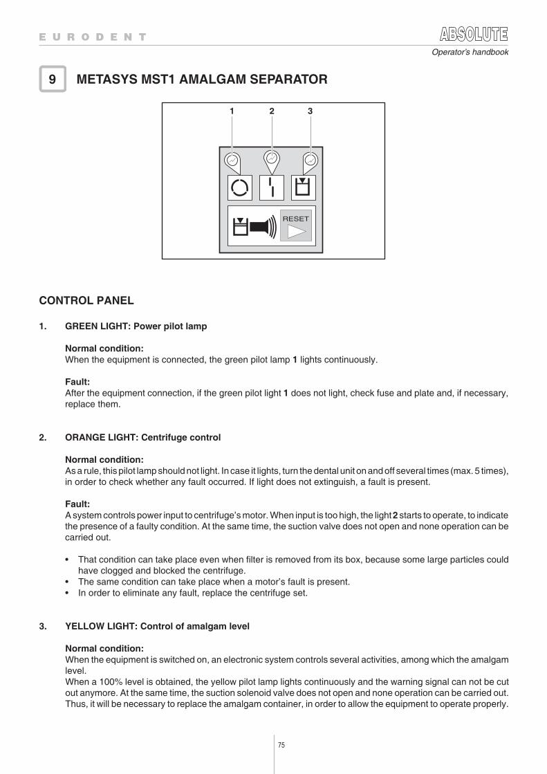
75
Operator’s handbook
CONTROL PANEL
1. GREEN LIGHT: Power pilot lamp
Normal condition:When the equipment is connected, the green pilot lamp 1 lights continuously.
Fault:After the equipment connection, if the green pilot light 1 does not light, check fuse and plate and, if necessary,replace them.
2. ORANGE LIGHT: Centrifuge control
Normal condition:As a rule, this pilot lamp should not light. In case it lights, turn the dental unit on and off several times (max. 5 times),in order to check whether any fault occurred. If light does not extinguish, a fault is present.
Fault:A system controls power input to centrifuge’s motor. When input is too high, the light 2 starts to operate, to indicatethe presence of a faulty condition. At the same time, the suction valve does not open and none operation can becarried out.
• That condition can take place even when filter is removed from its box, because some large particles couldhave clogged and blocked the centrifuge.
• The same condition can take place when a motor’s fault is present.• In order to eliminate any fault, replace the centrifuge set.
3. YELLOW LIGHT: Control of amalgam level
Normal condition:When the equipment is switched on, an electronic system controls several activities, among which the amalgamlevel.When a 100% level is obtained, the yellow pilot lamp lights continuously and the warning signal can not be cutout anymore. At the same time, the suction solenoid valve does not open and none operation can be carried out.Thus, it will be necessary to replace the amalgam container, in order to allow the equipment to operate properly.
METASYS MST1 AMALGAM SEPARATOR9
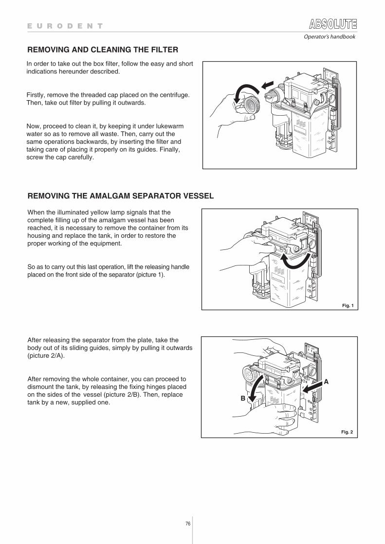
76
Operator’s handbook
REMOVING AND CLEANING THE FILTER
REMOVING THE AMALGAM SEPARATOR VESSEL
When the illuminated yellow lamp signals that thecomplete filling up of the amalgam vessel has beenreached, it is necessary to remove the container from itshousing and replace the tank, in order to restore theproper working of the equipment.
So as to carry out this last operation, lift the releasing handleplaced on the front side of the separator (picture 1).
After releasing the separator from the plate, take thebody out of its sliding guides, simply by pulling it outwards(picture 2/A).
After removing the whole container, you can proceed todismount the tank, by releasing the fixing hinges placedon the sides of the vessel (picture 2/B). Then, replacetank by a new, supplied one.
In order to take out the box filter, follow the easy and shortindications hereunder described.
Firstly, remove the threaded cap placed on the centrifuge.Then, take out filter by pulling it outwards.
Now, proceed to clean it, by keeping it under lukewarmwater so as to remove all waste. Then, carry out thesame operations backwards, by inserting the filter andtaking care of placing it properly on its guides. Finally,screw the cap carefully.
MULTISYSTEM
MULTISYSTEM
A
B
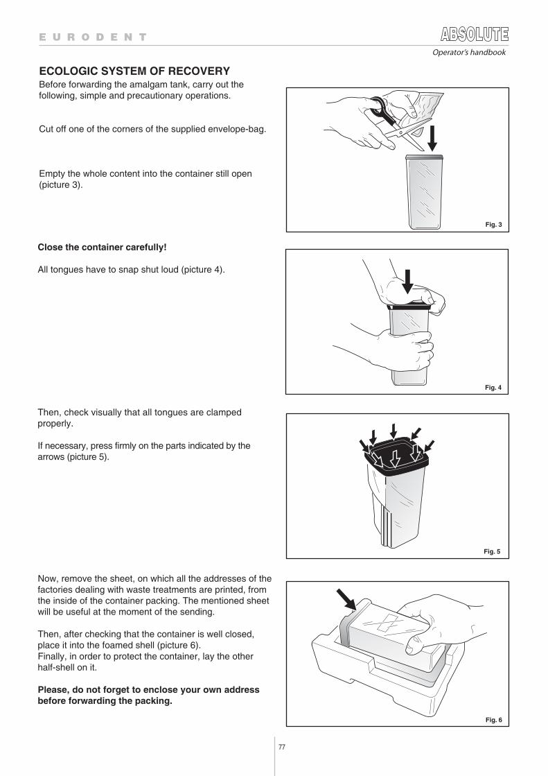
77
Operator’s handbook
ECOLOGIC SYSTEM OF RECOVERYBefore forwarding the amalgam tank, carry out thefollowing, simple and precautionary operations.
Cut off one of the corners of the supplied envelope-bag.
Empty the whole content into the container still open(picture 3).
Close the container carefully!
All tongues have to snap shut loud (picture 4).
Then, check visually that all tongues are clampedproperly.
If necessary, press firmly on the parts indicated by thearrows (picture 5).
Now, remove the sheet, on which all the addresses of thefactories dealing with waste treatments are printed, fromthe inside of the container packing. The mentioned sheetwill be useful at the moment of the sending.
Then, after checking that the container is well closed,place it into the foamed shell (picture 6).Finally, in order to protect the container, lay the otherhalf-shell on it.
Please, do not forget to enclose your own addressbefore forwarding the packing.
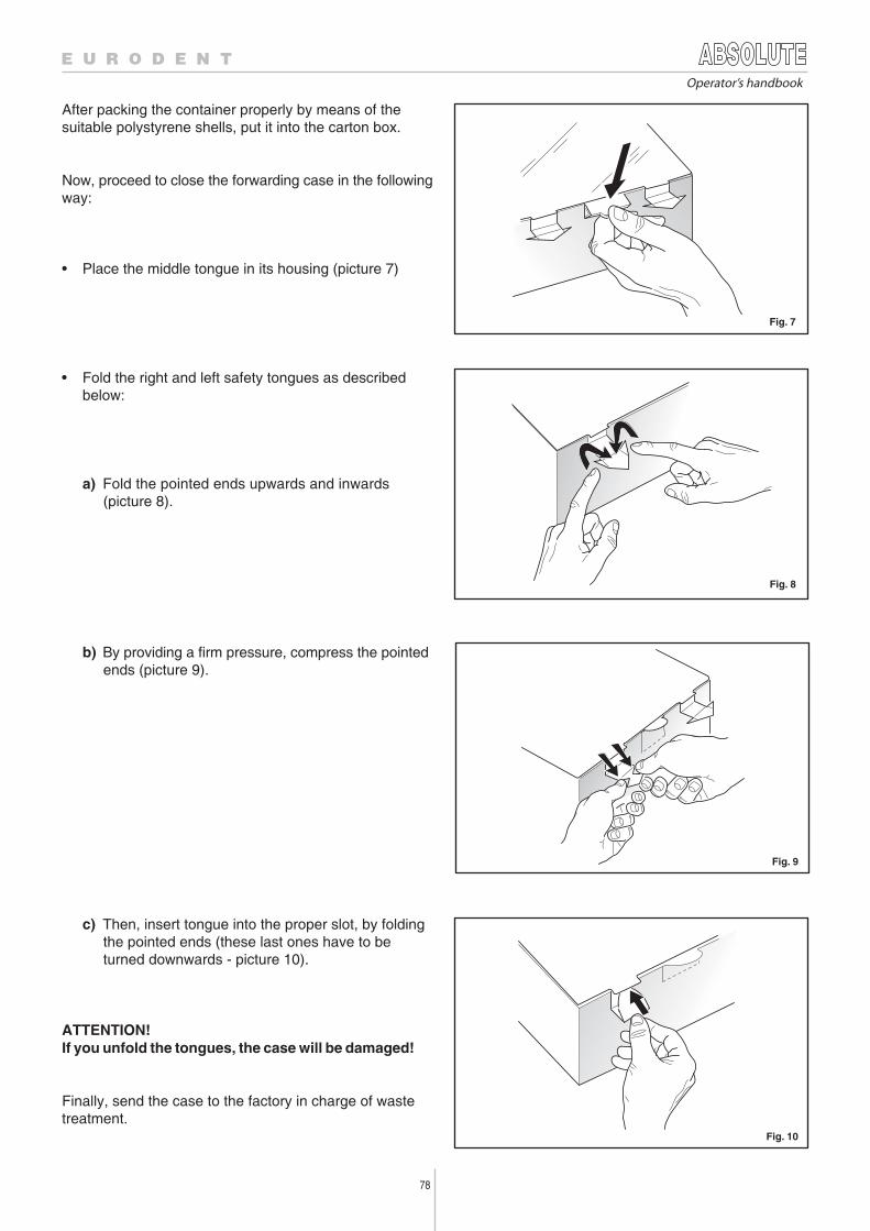
78
Operator’s handbook
• Fold the right and left safety tongues as describedbelow:
a) Fold the pointed ends upwards and inwards(picture 8).
After packing the container properly by means of thesuitable polystyrene shells, put it into the carton box.
Now, proceed to close the forwarding case in the followingway:
• Place the middle tongue in its housing (picture 7)
b) By providing a firm pressure, compress the pointedends (picture 9).
c) Then, insert tongue into the proper slot, by foldingthe pointed ends (these last ones have to beturned downwards - picture 10).
ATTENTION!If you unfold the tongues, the case will be damaged!
Finally, send the case to the factory in charge of wastetreatment.


![Wallot c. Québec (Ville de) 2010 QCCS 1370 · MARIE MASSON, Intervenants _____ JUGEMENT _____ [1] "There is no such thing as absolute ownership. Ownership is being modified constantly](https://img.pdfslide.fr/doc/110x75/5fab6096bf8c3804de21f6fb/wallot-c-qubec-ville-de-2010-qccs-1370-marie-masson-intervenants-jugement.jpg)


![[eng] AGRICULTURAL PRICES : Price indices and absolute ... · agricultural production Eurostat publications on agricultural price statistics Page 5 Signes et abréviations employés](https://img.pdfslide.fr/doc/110x75/5f82febcf143ec7a1a0d0d02/eng-agricultural-prices-price-indices-and-absolute-agricultural-production.jpg)