Embed Size (px)
Citation preview
es
es
PHYSICAL REVIEW B 66, 245301 ~2002!
Self-consistent three-dimensional models for quantum ballistic transport in open systems
E. PolizziLaboratoire des Mathe´matiques pour l’Industrie et la Physique, Unite´ Mixte de Recherche CNRS 5640, Institut National des Scienc
Appliques, departement de Ge´nie Mathematique et Modelisation, 135 Avenue de Rangueil, 31077 Toulouse Cedex 4, France
N. Ben AbdallahLaboratoire des Mathe´matiques pour l’Industrie et la Physique, Unite´ Mixte de Recherche CNRS 5640, Institut National des Scienc
Appliques, departement de Ge´nie Mathematique et Modelisation, 118 Route de Narbonne, 31062 Toulouse Cedex 4, France~Received 12 November 2001; revised manuscript received 29 May 2002; published 4 December 2002!
A quasi-three-dimensional model for quantum ballistic transport in nanostructures is proposed. The modelgoes beyond the Thomas-Fermi approximation and is numerically more tractable than the full three-dimensional Schro¨dinger-Poisson model. Its derivation relies on the strong confinement of electrons at theheterojunction which allows us to split the three-dimensional Schro¨dinger equation into a one-dimensionalSchrodinger equation for the confined direction and a two-dimensional Schro¨dinger equation in the transportdirection. The space charge effects are taken into account in a three-dimensional framework. Numericalsimulations of quantum waveguide devices such as T stubs and directional couplers are used to illustrate theaccuracy of the quasi-3D model versus the fully 3D model and to show the importance of quantum effects.
DOI: 10.1103/PhysRevB.66.245301 PACS number~s!: 75.40.Mg, 75.10.Jm, 02.70.2c
rswent
otico
be
tha, tn
y
yn-dethf tros--
odne
rtim
Fis-issilyinginctoffed.eslfor
go-
thed-al
Ref.e-
ee-unthatal.ith
e-oe-ro-imu-er,een
enterrge
wo-
I. INTRODUCTION
Nanoscale split-gate devices such as quantum couplestubs, etc., whose operation relies on the formation of a tdimensional electron gas~2DEG! and on wave interferenceffects, have been widely studied both from the experimeand theoretical point of view.1–12 At low temperatures, andthanks to the confinement of electrons in the 2DEG, the mbility is sufficiently high to consider the transport as ballisalong the 2DEG.13–15Therefore, the von Neumann or Schr¨-dinger pictures are suitable. In the latter, electrons canrepresented by a mixed state with given statistics, eachementary state being the solution of the Schro¨dinger equa-tion with open boundary conditions.
Since the conductance is very sensitive to the value ofelectrostatic potential, an accurate computation of spcharge effects has to be done. For numerical reasonselectrostatic potential used to be computed self-consistein the Thomas-Fermi approximation.9 Once the potential isobtained, the conductance is computed either by the KeldGreen’s functions16–22or mode matching techniques~the lat-ter method requires the replacement of the potential bhard wall potential!.23–26 The Thomas-Fermi approximatiois only valid for equilibrium situations and for slowly varying electrostatic potentials. This is not the case for thevices we are interested in, as will be illustrated in the forcoming sections. Therefore, an accurate representation oelectrostatic potential requires the resolution of the Sch¨-dinger equations~thus allowing us to go beyond the ThomaFermi approximation!. We shall perform this program by using the Lent and Kirkner boundary conditions27 for eachwave function@the quantum transmitting boundary meth~QTBM!, analogous results in electromagnetic were obtaiin particular by Nedelec and Starling28#. Let us mention thatthe Schro¨dinger picture is suitable for ballistic transposince the density matrix is diagonal. When collisions areportant, this approach is difficult to generalize~we, however,
0163-1829/2002/66~24!/245301~9!/$20.00 66 2453
, To-
al
-
el-
ecehetly
sh
a
--he
d
-
mention the Pauli master equation approach proposed bychetti in Ref. 29!. The Keldysh Green’s function approachmeeting an increasing interest since it allows us to eatake into account collisions. The idea consists in computthe density matrix directly by solving the Dyson equation,which the collision can be incorporated in a rather direway. The method is, however, very time consuming sincediagonal terms of the density matrix have to be computThis results in doubling the number of position variablcompared to the Schro¨dinger picture. In three-dimensionasituations, this leads to a six-dimensional Dyson equationwhich the numerical cost is high. Let us mention21 where anew recursive Green’s method is proposed for block dianal Green’s functions.
The method that we propose in this paper is based onSchrodinger equation with the quantum transmitting bounary method. Numerical simulations in the two-dimensioncase, without space charge effects, were performed in30. In order to reduce the numerical complexity in the thredimensional case, we propose a simplified quasi-thrdimensional model, which simultaneously takes into accothe confinement of electrons in the 2DEG and the fact tthe electrostatic potential is completely three-dimensionThis quasi-three-dimensional model is then compared wthe fully three-dimensional one.
The outline of the paper is as follows. After having rcalled the three-dimensional Schro¨dinger-Poisson system tbe solved~Sec. II!, we present in Sec. III the quasi-thredimensional model. Section IV deals with the numerical pcedure used to solve the defined coupled systems. The slations of a T stub and a quantum directional couplpresented in Sec. V, show a satisfactory agreement betwthe three-dimensional Schro¨dinger-Poisson model and thquasi-three-dimensional one~charge density, transmissiospectra, etc!, whose resolution requires much less compuresources. The comparison with classical models for chadensity based on the three-dimensional and the t
©2002 The American Physical Society01-1
tho
dumwle
n
d
to
l
o
for
ndtiallv-
nt-
onr-ero
thebe
thenpo-men in
rge
ua-de-ofw
ico
E. POLIZZI AND N. BEN ABDALLAH PHYSICAL REVIEW B 66, 245301 ~2002!
dimensional Thomas-Fermi approximations shows thatSchrodinger approach is necessary to correctly model nancale split-gate devices.
II. THE THREE-DIMENSIONALSCHRODINGER-POISSON SYSTEM
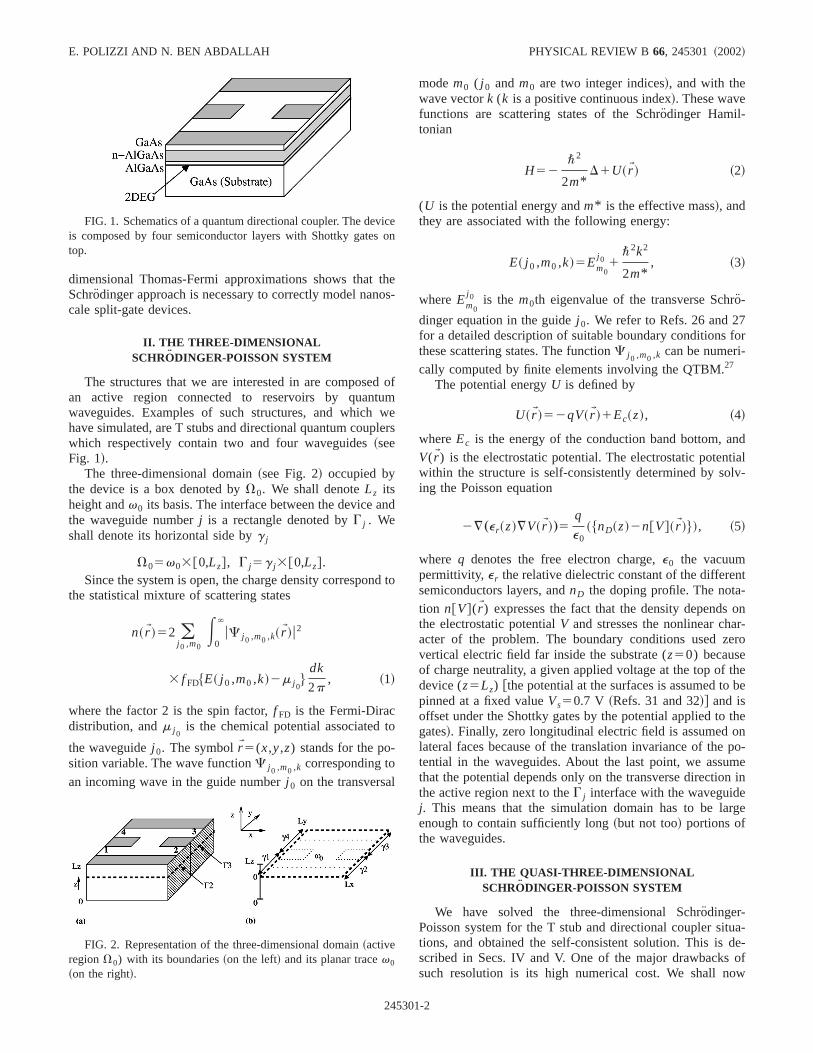
The structures that we are interested in are composean active region connected to reservoirs by quantwaveguides. Examples of such structures, and whichhave simulated, are T stubs and directional quantum coupwhich respectively contain two and four waveguides~seeFig. 1!.
The three-dimensional domain~see Fig. 2! occupied bythe device is a box denoted byV0. We shall denoteLz itsheight andv0 its basis. The interface between the device athe waveguide numberj is a rectangle denoted byG j . Weshall denote its horizontal side byg j
V05v03@0,Lz#, G j5g j3@0,Lz#.Since the system is open, the charge density correspon
the statistical mixture of scattering states
n~rW !52 (j 0 ,m0
E0
`
uC j 0 ,m0 ,k~rW !u2
3 f FD$E~ j 0 ,m0 ,k!2m j 0%
dk
2p, ~1!
where the factor 2 is the spin factor,f FD is the Fermi-Diracdistribution, andm j 0
is the chemical potential associated
the waveguidej 0. The symbolrW5(x,y,z) stands for the po-sition variable. The wave functionC j 0 ,m0 ,k corresponding to
an incoming wave in the guide numberj 0 on the transversa
FIG. 1. Schematics of a quantum directional coupler. The devis composed by four semiconductor layers with Shottky gatestop.
FIG. 2. Representation of the three-dimensional domain~activeregionV0) with its boundaries~on the left! and its planar tracev0
~on the right!.
24530
es-
of
ers
d
to
modem0 ( j 0 andm0 are two integer indices!, and with thewave vectork (k is a positive continuous index!. These wavefunctions are scattering states of the Schro¨dinger Hamil-tonian
H52\2
2m*D1U~rW ! ~2!
(U is the potential energy andm* is the effective mass!, andthey are associated with the following energy:
E~ j 0 ,m0 ,k!5Em0
j 0 1\2k2
2m*, ~3!
whereEm0
j 0 is the m0th eigenvalue of the transverse Schr¨-
dinger equation in the guidej 0. We refer to Refs. 26 and 27for a detailed description of suitable boundary conditionsthese scattering states. The functionC j 0 ,m0 ,k can be numeri-cally computed by finite elements involving the QTBM.27
The potential energyU is defined by
U~rW !52qV~rW !1Ec~z!, ~4!
whereEc is the energy of the conduction band bottom, aV(rW) is the electrostatic potential. The electrostatic potenwithin the structure is self-consistently determined by soing the Poisson equation
2¹„e r~z!¹V~rW !…5q
e0~$nD~z!2n@V#~rW !%!, ~5!
where q denotes the free electron charge,e0 the vacuumpermittivity, e r the relative dielectric constant of the differesemiconductors layers, andnD the doping profile. The notation n@V#(rW) expresses the fact that the density dependsthe electrostatic potentialV and stresses the nonlinear chaacter of the problem. The boundary conditions used zvertical electric field far inside the substrate (z50) becauseof charge neutrality, a given applied voltage at the top ofdevice (z5Lz) @the potential at the surfaces is assumed topinned at a fixed valueVs50.7 V ~Refs. 31 and 32!# and isoffset under the Shottky gates by the potential applied togates!. Finally, zero longitudinal electric field is assumed olateral faces because of the translation invariance of thetential in the waveguides. About the last point, we assuthat the potential depends only on the transverse directiothe active region next to theG j interface with the waveguidej. This means that the simulation domain has to be laenough to contain sufficiently long~but not too! portions ofthe waveguides.
III. THE QUASI-THREE-DIMENSIONALSCHRODINGER-POISSON SYSTEM
We have solved the three-dimensional Schro¨dinger-Poisson system for the T stub and directional coupler sittions, and obtained the self-consistent solution. This isscribed in Secs. IV and V. One of the major drawbackssuch resolution is its high numerical cost. We shall no
en
1-2
nt o
y
ei-
op
s
ave
y
e
:
he
rob-
e
by
ne
s-rynsi-areitieste
thend-
SELF-CONSISTENT-THREE DIMENSIONAL MODELS . . . PHYSICAL REVIEW B 66, 245301 ~2002!
present a model that we call the quasi-three-dimensiomodel which takes into account the strong confinemenelectrons in thez direction.
A. Description of the model
The 3D potential energyU(rW) can be separated arbitrarilinto a potentialU1 depending on the verticalz direction, apotentialU2 depending onx,y, and a potentialu(rW), suchthat
U~rW !5U1~z!1U2~x,y!1u~rW !. ~6!
Let fn be the normalized eigenfunction solving the 1Dgenvalue problem
2\2
2m*
d2
dz2fn~z!1U1~z!fn~z!5Eznfn~z!, ~7!
with Dirichlet boundary conditions equal to zero at the tand the bottom of the device~respectively z50 and z5Lz). The three-dimensional wave functionCE can be ex-panded on thefn’s
CE5 (n51
`
cn~x,y!fn~z!, ~8!
In the particular case ofu50, the wave functioncn sat-isfies this 2D Schro¨dinger equation
2\2
2m*Dx,yc
n~x,y!1U2~x,y!cn~x,y!5~E2Ezn!cn~x,y!.
~9!
In the general case,uÞ0, the wave functioncn is thensolution of the 2D Schro¨dinger equation~9! where the termU2cn is replaced by
U2~x,y!cn~x,y!1(n8
cn8~x,y!S E0
Lzfn~z!u~rW !fn8~z!dzD ,
~10!
and involves nondiagonal terms~those corresponding ton8Þn).
The quasi-3D model consists in assuming thatu is aslowly varying function compared tofn around the electrongas in thez direction, and neglecting the off-diagonal termof Eq. ~10!. cn is now the solution of a new 2D Schro¨dingerequation
2\2
2m*Dx,yc
n~x,y!1Un~x,y!cn~x,y!5~E2Ezn!cn~x,y!,
~11!
where the potential energy on the band numbern is given byUn(x,y)5U2(x,y)1*0
Lzu(rW)ufn(z)u2 dz, which can be re-written
Un~x,y!5E0
Lz@U~rW !2U1~z!#ufn~z!u2 dz. ~12!
24530
alf
Let fn0c j 0 ,p0 ,k
n0 be the wave function solving the
quasi-3D problem and corresponding to one incoming win the waveguidej 0, on the vertical moden0, and the trans-verse modep0 in the guide. Therefore the energy is given b
E~ j 0 ,p0 ,n0 ,k!5Ezn01Ep0 ,n0
j 0 1\2k2
2m*~13!
@where Ep0 ,n0
j 0 is the p0th eigenvalue of the 2D transvers
Schrodinger equation~11! in the guidej 0] and the expres-sion of the electron density takes now the following form
n~rW !5 (n051
`
ufn0~z!u2 n2D
n0 ~x,y!, ~14!
wheren2Dn0 is defined as the 2D density of electrons in t
vertical moden0
n2Dn0 ~x,y!52 (
j 0 ,p0
E0
`
uc j 0 ,p0 ,kn0 u2
3 f FD$E~ j 0 ,p0 ,n0 ,k!2m j 0%
dk
2p. ~15!
To summarize, the 3D wave function solution of Eq.~2!for a given energy can be separated in a 1D eigenvalue plem for the vertical z direction Eq. ~7!, and a two-dimensional Schro¨dinger equation~11! in the transport direc-tion with open boundary conditions at the limit of thwaveguidesg j .
B. Approximation orders
Let the surface density and the current density be given
ns~x,y!5E0
Lzn~rW !dz ~16!
and
J~rW !52 (j 0 ,m0
E0
`
j j 0 ,m0 ,k~rW ! f FD„E~ j 0 ,m0 ,k!2m j 0…
dk
2p,
~17!
where j j 0 ,m0 ,k(rW) is the current density associated with oscattering state
j j 0 ,m0 ,k~rW !5q\
m*Im$C j 0 ,m0 ,k~rW !¹C j 0 ,m0 ,k~rW !%. ~18!
We briefly summarize the results shown in Ref. 33. Asuming thatuuu!1, it can be shown using the stationaperturbation theory that the surface and the current inteties in the waveguides computed by the quasi-3D modelsecond order approximations of the corresponding quantof the fully 3D model. The quasi-3D model is more accurathan the fully decoupled model~in which u is set to zero!.Indeed, for the latter, the surface and current intensities inwaveguides are first order approximations of the correspo
1-3
i-
sth
rfaththice
ori-3
en.u
-
siong
es
-
a
t
o
eth
b-
E. POLIZZI AND N. BEN ABDALLAH PHYSICAL REVIEW B 66, 245301 ~2002!
ing quantities of the fully 3D model. Moreover, the approxmation orders are still valid ifu is a slowly function com-pared tofn around the electron gas in thez direction ~it isnot necessary to haveuuu!1).
C. Description of the electron confinementthrough the quasi-3D model
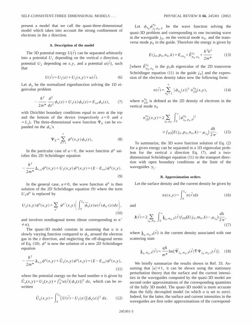
For a given potentialU, we need to define a potentialU1which depends only on thez direction. When a negative biapotential is applied to the gates on the top of the device,2DEG deserts the zones under the gates in which the sudensity is equal to zero. Figure 3 gives the potential anddensity vertical profile for a zone under the gates and foractive region where are localized the electrons. The vertpotential U1 is a potential which ‘‘must be seen’’ by thelectrons. Therefore, we define the potentialU1 as aweighted average in thex,y direction of the 3D potential
U1@V#~z!5
Ev0
U~rW !ns@V#~x,y!dxdy
Ev0
ns@V#~x,y!dxdy
. ~19!
The chosen weight is the surfacic density in order to ignthe contributions of deserted zones; see Fig. 3. The quasquantum model is defined by the coupled system, Eqs.~16!,~19!, ~7!, ~12!, ~15!, ~14!, ~4!, and~5!.
D. The current density
In this section we recall the expression of the current dsity in the waveguides using the transmission coefficients4,34
In the 3D case and for one incoming wave in the inpports j 0 and the transverse modem0, the transmission coefficient in the output portsj and the transverse modem isdefined by
FIG. 3. Vertical potential and density profiles for a T stub at twdifferent locations. In the active region~zone without gates on thetop! the density is localized in the 2DEG next to thAl xGa12xAs/GaAs interface, and in the zone under the gates,electron density is equal to zero.
24530
eceeeal
eD
-
t
Tj 0→ jm0→m
~E!5H kmj ~E!
km0
j 0 ~E!ubm
j u2 if E<Emj
0 else,
~20!
The total transmission coefficientTj 0→ j in the output portsj
from the input portj 0 is given by
Tj 0→ j~E!5 (m0 ,m
Tj 0→ jm0→m
~E!. ~21!
In the quasi-3D case, the results about the transmiscoefficient presented below are still valid with the followinchanges in expressions~20! and~21!: The indicesm0 andmbecome, respectively,n0 ,p0 andn,p ~the sums over the in-dicesm0 andm become, respectively, sums over the indicn0 ,p0 andn,p), andEm
j becomesEp,nj 0 1Ezn .
Therefore, the electric current between the portj 0 andj isgiven by
I j 0→ j5q
p\E0
`
Tj 0→ j~E! f FD~E2m j 0!dE, ~22!
and the total current in the portj which takes into account thecontribution of all portj 0 by
I j5 (j 0Þ j
~ I j 0→ j2I j→ j 0!. ~23!
We noteTj 0→ j5Tj→ j 0with the assumption of ballistic trans
port, and we obtain the following relation:
I j5q
p\ (j 0
E0
`
Tj 0→ j~E!@ f FD~E2m j 0!2 f FD~E2m j !#dE.
~24!
At equilibrium, the chemical potentials are all equal tosingle valuem. This implies with Eq.~24! that the currentsare all equal to zero. Denotingv j the applied bias at the porj, we obtain
e
TABLE I. Self-consistent 3D and quasi-3D models at equilirium (m j5m) and out of equilibrium.
3D model Quasi-3D model
m j5m Semiclassical HybridThomas-Fermi 3D Schro¨dinger 1D
Poisson 3D Thomas-Fermi 2DPoisson 3D
m j5m2qv j Quantum QuantumSchrodinger 3D Schro¨dinger 1D
Poisson 3D Schro¨dinger 2DPoisson 3D
1-4
heIt
rp
Bd
eden
the
ledricalginmut-
re-a-
b-
byumac-ten-
erth
SELF-CONSISTENT-THREE DIMENSIONAL MODELS . . . PHYSICAL REVIEW B 66, 245301 ~2002!
m j5m2qv j , ~25!
and the net current is nonvanishing.
IV. NUMERICAL PROCEDURE
The P1 finite element method is used to solve all tequations of the coupled systems on a same 3D mesh.convenient to construct the 3D mesh using parallel supesition of the same 2D mesh in thez direction since thequasi-3D models require a 1D mesh in thez direction tosolve the vertical eigenproblem~7!, and a 2D mesh onx,y tosolve the 2D Schro¨dinger equation~11!. The symmetric lin-ear complex sparse systems that we obtain with the QTapply to the 2D or 3D open Schro¨dinger equations are solveusing a quasiminimal residual~QMR! procedure.35 In order
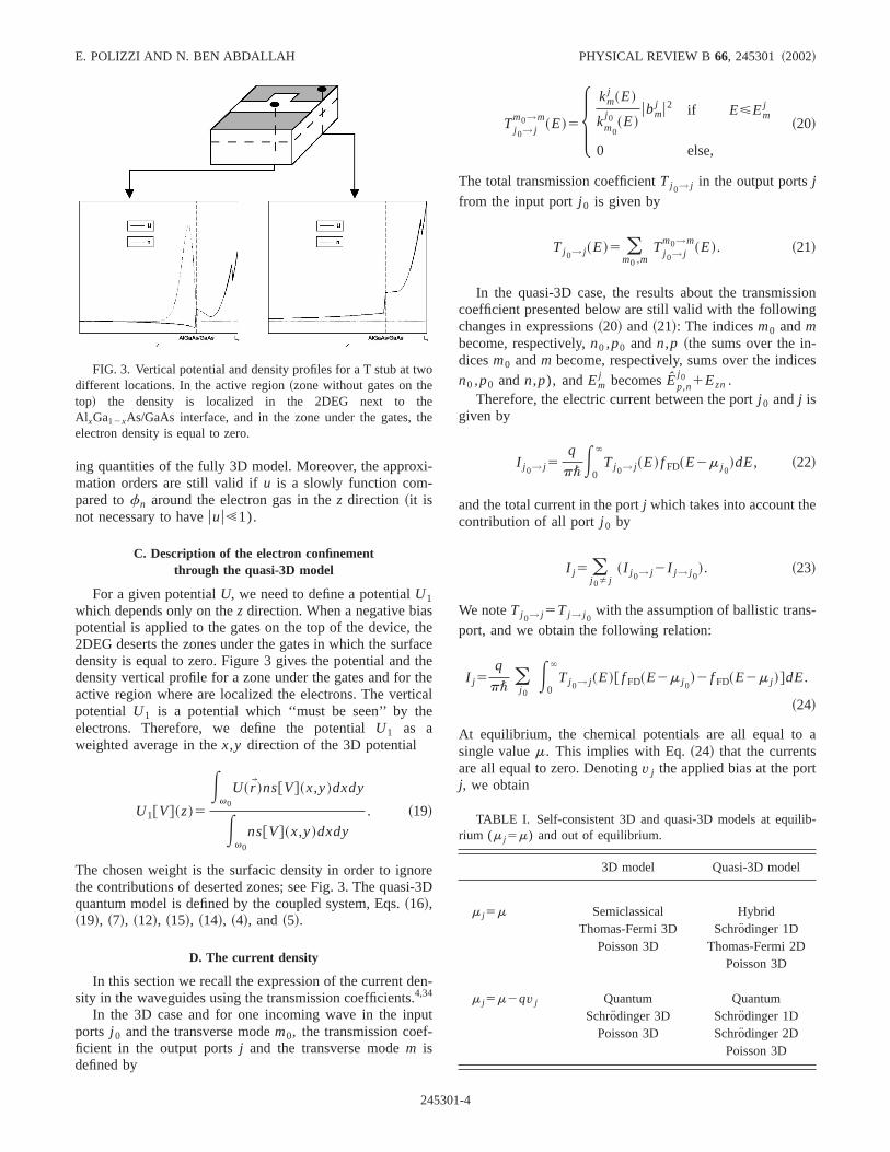
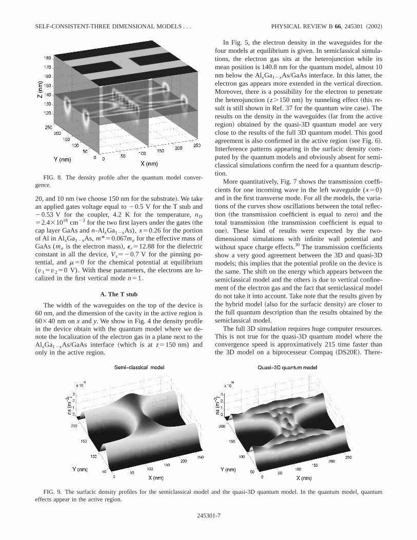
FIG. 4. The density profile after the quantum model convgence. Electrons are localized in the active region nearAl xGa12xAs/GaAs interface.
24530
iso-
M
to obtain the electron density for a given potential, we neto solve a large number of independent 2D or 3D opSchrodinger equations. Therefore, a parallel version ofcode was developed.
Because of the highly nonlinear character of the coupsystems, implicit schemes have to be used for the numeresolution. In order to obtain a suitable initial guess to bethe 3D and quasi-3D quantum simulations at equilibriu~with no applied bias voltage between the input and the oput terminals of the structures!, we use the well-knownThomas-Fermi semiclassical approximation. We brieflycall the expression of the electron density in this approximtion
n@V~rW !#5A2
p2 S m*
b\2D 3/2
F1/2„b@m2U~rW !#…, ~26!
wherem is the chemical potential of the system at equilirium, b51/(kBT), andF1/2(h f) is the Fermi-Dirac integralgiven by
F1/2~h f !5E0
` h1/2
11exp~h2h f !dh. ~27!
The obtained 3D Thomas-Fermi/Poisson system is solvedstandard Newton method. However, for the 3D quantmodel and quasi-3D models the Newton method is not prtical because the density depends non locally on the potial. Therefore, we use the Gummel iterations36 and for agiven potentialVn at the stepn, the new potentialVn11 isnow given by
2¹[ ~e r~z!¹Vn11~rW !#1q
e0n~rW !
Vn11
Vref
5q
e0FnD~z!2n~rW !S 12
Vn
VrefD G , ~28!
-e
ty
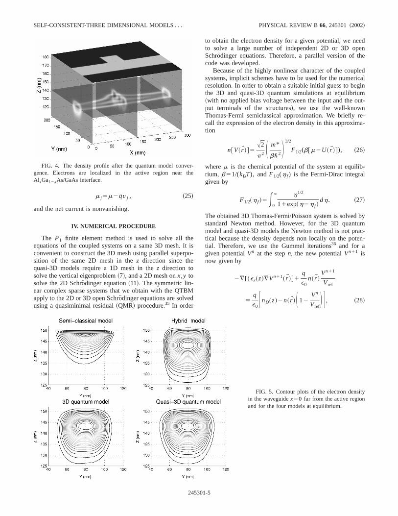
FIG. 5. Contour plots of the electron densiin the waveguidex50 far from the active regionand for the four models at equilibrium.1-5
f-
E. POLIZZI AND N. BEN ABDALLAH PHYSICAL REVIEW B 66, 245301 ~2002!
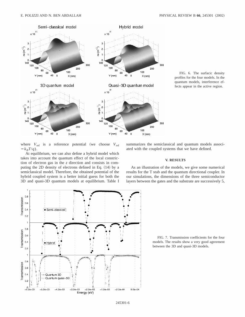
FIG. 6. The surfacic densityprofiles for the four models. In thequantum models, interference efects appear in the active region.
hric-
ththe
soci-
al. Inctorely 5,
where Vref is a reference potential~we choose Vref5kBT/q).
At equilibrium, we can also define a hybrid model whictakes into account the quantum effect of the local consttion of electron gas in thez direction and consists in computing the 2D density of electrons defined in Eq.~14! by asemiclassical model. Therefore, the obtained potential ofhybrid coupled system is a better initial guess for both3D and quasi-3D quantum models at equilibrium. Tabl
24530
-
eeI
summarizes the semiclassical and quantum models asated with the coupled systems that we have defined.
V. RESULTS
As an illustration of the models, we give some numericresults for the T stub and the quantum directional couplerour simulations, the dimensions of the three semicondulayers between the gates and the substrate are successiv
rent
FIG. 7. Transmission coefficients for the foumodels. The results show a very good agreembetween the 3D and quasi-3D models.
1-6
f
lo
ii
edeth
hela-its10
etion.ate
ryod
om-mi-rip-
ffi-
ria-ec-
too-dsi-3Disthe
ne-odelby
the
es.thehan
er
SELF-CONSISTENT-THREE DIMENSIONAL MODELS . . . PHYSICAL REVIEW B 66, 245301 ~2002!
20, and 10 nm~we choose 150 nm for the substrate!. We takean applied gates voltage equal to20.5 V for the T stub and20.53 V for the coupler, 4.2 K for the temperature,nD52.431018 cm23 for the two first layers under the gates~thecap layer GaAs andn-Al xGa12xAs), x50.26 for the portionof Al in Al xGa12xAs, m* 50.067me for the effective mass oGaAs (me is the electron mass!, e r512.88 for the dielectricconstant in all the device,Vs520.7 V for the pinning po-tential, andm50 for the chemical potential at equilibrium(v15v250 V). With these parameters, the electrons arecalized in the first vertical moden51.
A. The T stub
The width of the waveguides on the top of the device60 nm, and the dimension of the cavity in the active region60340 nm onx andy. We show in Fig. 4 the density profilin the device obtain with the quantum model where wenote the localization of the electron gas in a plane next toAl xGa12xAs/GaAs interface~which is at z5150 nm) andonly in the active region.
FIG. 8. The density profile after the quantum model convgence.
24530
-
ss
-e
In Fig. 5, the electron density in the waveguides for tfour models at equilibrium is given. In semiclassical simutions, the electron gas sits at the heterojunction whilemean position is 140.8 nm for the quantum model, almostnm below the AlxGa12xAs/GaAs interface. In this latter, thelectron gas appears more extended in the vertical direcMoreover, there is a possibility for the electron to penetrthe heterojunction (z.150 nm) by tunneling effect~this re-sult is still shown in Ref. 37 for the quantum wire case!. Theresults on the density in the waveguides~far from the activeregion! obtained by the quasi-3D quantum model are veclose to the results of the full 3D quantum model. This goagreement is also confirmed in the active region~see Fig. 6!.Interference patterns appearing in the surfacic density cputed by the quantum models and obviously absent for seclassical simulations confirm the need for a quantum desction.
More quantitatively, Fig. 7 shows the transmission coecients for one incoming wave in the left waveguide (x50)and in the first transverse mode. For all the models, the vations of the curves show oscillations between the total refltion ~the transmission coefficient is equal to zero! and thetotal transmission~the transmission coefficient is equalone!. These kind of results were expected by the twdimensional simulations with infinite wall potential anwithout space charge effects.30 The transmission coefficientshow a very good agreement between the 3D and quasmodels; this implies that the potential profile on the devicethe same. The shift on the energy which appears betweensemiclassical model and the others is due to vertical confiment of the electron gas and the fact that semiclassical mdo not take it into account. Take note that the results giventhe hybrid model~also for the surfacic density! are closer tothe full quantum description than the results obtained bysemiclassical model.
The full 3D simulation requires huge computer resourcThis is not true for the quasi-3D quantum model whereconvergence speed is approximatively 215 time faster tthe 3D model on a biprocesseur Compaq~DS20E!. There-
-
quantum
FIG. 9. The surfacic density profiles for the semiclassical model and the quasi-3D quantum model. In the quantum model,effects appear in the active region.1-7
ubl
ith
thsu
oortu
e
thu
ivew
iorst
umm
aythen
ec-e-els
3Dom-ali-en
d onre-m-or-de,hy.ch
o
O.ofs
uc-
ng in-
E. POLIZZI AND N. BEN ABDALLAH PHYSICAL REVIEW B 66, 245301 ~2002!
fore, the quasi-3D model can be used practically to compcurrent-voltage characteristics while it is quasi impossifor the 3D model.
B. The quantum directional coupler
The width of the waveguides on the top of the device50 nm, and the dimension of the coupling branch inmiddle of the device is 50360 nm onx andy. The geometryof the quantum directional coupler is more complex thangeometry of the T stub; then the number of the mesh nodealso more important. The 3D quantum model in the quantcoupler case is then numerical expensive~the size of thelinear systems obtained by solving the Schro¨dinger equationsis too large to expect a result in relevant times!. Therefore,we assume that the quasi-3D quantum model is a very gapproximation of the full quantum model as it is shown fthe T-stub case, and we only use this model for the quancoupler simulations.
Figure 8 shows the density profile in the device obtainwith the quasi-3D quantum model.
The mean position of the electron gas plane belowAl xGa12xAs/GaAs interface is equal to 139.6 nm. The simlation exhibits very important quantum effects in the actregion. This is not true for the semiclassical model, as shoin Fig. 9 for the surfacic density.
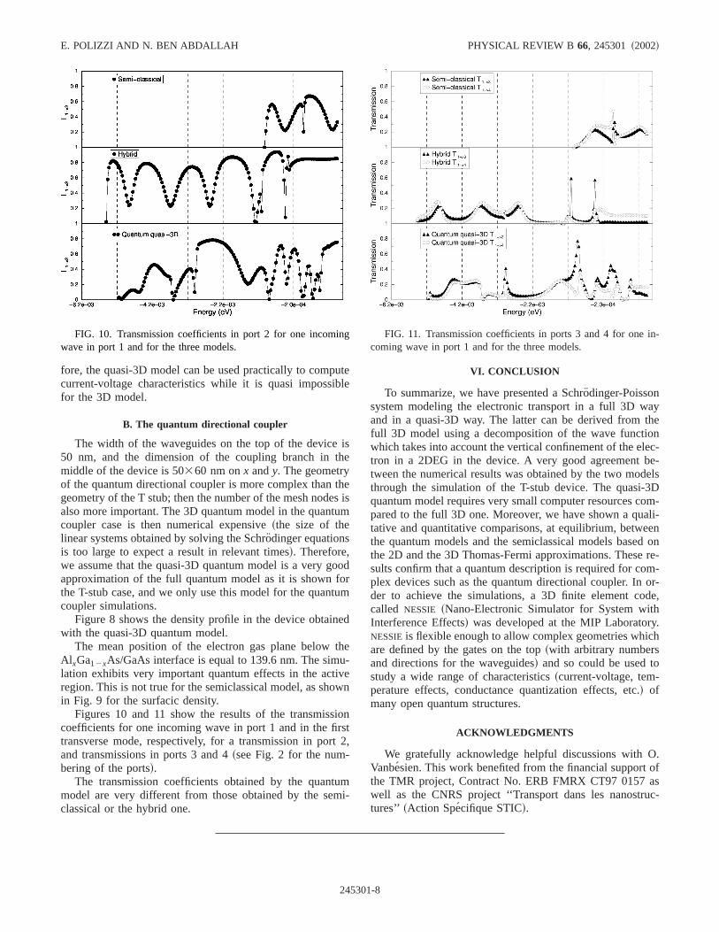
Figures 10 and 11 show the results of the transmisscoefficients for one incoming wave in port 1 and in the fitransverse mode, respectively, for a transmission in porand transmissions in ports 3 and 4~see Fig. 2 for the num-bering of the ports!.
The transmission coefficients obtained by the quantmodel are very different from those obtained by the seclassical or the hybrid one.
FIG. 10. Transmission coefficients in port 2 for one incomiwave in port 1 and for the three models.
24530
tee
se
eis
m
od
m
d
e-
n
nt2,
i-
VI. CONCLUSION
To summarize, we have presented a Schro¨dinger-Poissonsystem modeling the electronic transport in a full 3D wand in a quasi-3D way. The latter can be derived fromfull 3D model using a decomposition of the wave functiowhich takes into account the vertical confinement of the eltron in a 2DEG in the device. A very good agreement btween the numerical results was obtained by the two modthrough the simulation of the T-stub device. The quasi-quantum model requires very small computer resources cpared to the full 3D one. Moreover, we have shown a qutative and quantitative comparisons, at equilibrium, betwethe quantum models and the semiclassical models basethe 2D and the 3D Thomas-Fermi approximations. Thesesults confirm that a quantum description is required for coplex devices such as the quantum directional coupler. Inder to achieve the simulations, a 3D finite element cocalled NESSIE ~Nano-Electronic Simulator for System witInterference Effects! was developed at the MIP LaboratorNESSIEis flexible enough to allow complex geometries whiare defined by the gates on the top~with arbitrary numbersand directions for the waveguides! and so could be used tstudy a wide range of characteristics~current-voltage, tem-perature effects, conductance quantization effects, etc.! ofmany open quantum structures.
ACKNOWLEDGMENTS
We gratefully acknowledge helpful discussions withVanbesien. This work benefited from the financial supportthe TMR project, Contract No. ERB FMRX CT97 0157 awell as the CNRS project ‘‘Transport dans les nanostrtures’’ ~Action Specifique STIC!.
FIG. 11. Transmission coefficients in ports 3 and 4 for onecoming wave in port 1 and for the three models.
1-8
in7
. B
rri
m
J
l.
ky,
R.
pl.
.
SELF-CONSISTENT-THREE DIMENSIONAL MODELS . . . PHYSICAL REVIEW B 66, 245301 ~2002!
1See, for example, D.K. Ferry and S.M. Goodnick, TransportNanostructures~Cambridge University Press, Cambridge, 199!.
2N. Tsukada, A.D. Wieck, and K. Ploog, Appl. Phys. Lett.56, 2527~1990!.
3J. Wang, H. Guo, and R. Harris, Appl. Phys. Lett.59, 3075~1991!.
4M. Buttiker, Y. Imry, R. Landauer, and S. Pinhas, Phys. Rev31, 6207~1985!.
5J.O.J. Wesstro¨m, Appl. Phys. Lett.82, 2564~1999!.6G. Xu, Y. Yang, and P. Jiang, J. Appl. Phys.74, 6747~1993!.7O. Vanbesien and D. Lippens, Appl. Phys. Lett.65, 2439~1994!.8F. Sols, M. Macucci, U. Ravaioli, and K. Hess, J. Appl. Phys.66,
3892 ~1989!.9T. Palm, J. Appl. Phys.74, 3551~1993!.
10J.A. Del Alamo and C.C. Eugster, Appl. Phys. Lett.51, 78 ~1990!.11P. Debray, O.E. Raichev, P. Vasilopoulos, M. Rahman, R. Pe
and W.C. Mitchell, Phys. Rev. B61, 10 950~2000!.12S. Datta, M.R. Melloch, S. Bandyopadhyay, and M.S. Lundstro
Appl. Phys. Lett.48, 487 ~1986!.13T. Ando, A.B. Fowler, and F. Stern, Rev. Mod. Phys.54, 437
~1982!.14J.J. Harris, C.T. Foxon, K.W.J. Barnham, D.E. Lacklison,
Hewett, and C. White, J. Appl. Phys.61, 1219~1986!.15L. Pfeiffer, K.W. West, H.L. Stormer, and K.W. Baldwin, App
Phys. Lett.55, 1888~1989!.16G. Iannaccone, A. Trellakis, and U. Ravaioli, J. Appl. Phys.84,
5032 ~1998!.17L.V. Keldysh, Zh. Eksp. Teor. Fiz.47, 1945 ~1964! @Sov. Phys.
JETP20, 1018~1965!#.
24530
n,
,
.
18M. Macucci, A. Galick, and U. Ravaioli, Phys. Rev. B52, 5210~1995!.
19H. Tsuchiya and T. Miyoshi, J. Appl. Phys.83, 2574~1998!.20S. Sanvito, C.J. Lambert, J.H. Jefferson, and A.M. Bratkovs
Phys. Rev. B59, 11 936~1999!.21A. Svizhenko, M.P. Anantram, T.R. Govindan, B. Biegel, and
Venugopal, J. Appl. Phys.91, 2343~2002!.22J. Taylor, H. Guo, and J. Wang, Phys. Rev. B63, 245407~2001!.23J.A. Nixon, J.H. Davies, and H.U. Baranger, Phys. Rev. B43,
12 638~1991!.24A. Weisshaar, J. Lary, S.M. Goodnick, and V.K. Tripathi, J. Ap
Phys.70, 355 ~1991!.25E. Tekman and S. Ciraci, Phys. Rev. B39, 8772~1989!.26A. Szafer and A.D. Stone, Phys. Rev. Lett.62, 300 ~1989!.27C.S. Lent and D.J. Kirkner, J. Appl. Phys.67, 6353~1990!.28J.C. Nedelec and F. Starling, SIAM~Soc. Ind. Appl. Math.! J.
Math. Anal.22, 1679~1991!.29M.V. Fischetti, Phys. Rev. B59, 4901~1999!.30E. Polizzi, N. Ben Abdallah, O. Vanbe´sien, and D. Lippens, J
Appl. Phys.87, 8700~2000!.31J.H. Davies, Semicond. Sci. Technol.3, 995 ~1988!.32M. Chen, W. Porod, and D.J. Kirkner, J. Appl. Phys.75, 2545
~1994!.33E. Polizzi, PhD. Thesis, INSA, Toulouse, France~2001!.34S. Datta and M.J. McLennan, Rep. Prog. Phys.53, 1003~1990!.35R.W. Freund, SIAM~Soc. Ind. Appl. Math.! J. Sci. Stat. Comput.
12, 425 ~1992!; 14, 470 ~1993!.36H.K. Gummel, IEEE Trans. Electron Devices11, 455 ~1964!.37Z. Wu and P.P. Ruden, J. Appl. Phys.74, 6234~1993!.
1-9


![Correlations in low-dimensional quantum gases · (2015),Ref.[1] (ii) GuillaumeLang, Frank Hekking and Anna Minguzzi, Dimensional crossover in a Fermigasandacross-dimensionalTomonaga-Luttingermodel,Phys](https://img.pdfslide.fr/doc/110x75/5f03498f7e708231d40877ef/correlations-in-low-dimensional-quantum-gases-2015ref1-ii-guillaumelang.jpg)