Embed Size (px)
Citation preview
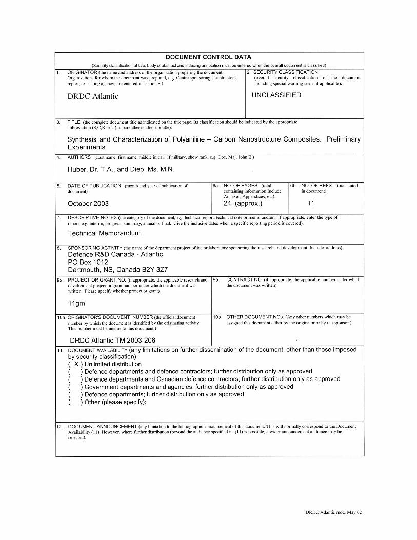
Defence R&D Canada
DEFENCE DÉFENSE&
Synthesis and Characterization of Polyaniline –
Carbon Nanostructure CompositesPreliminary Experiments
Trisha A. HuberDRDC Atlantic
Mary N. DiepDRA – University of Waterloo
Technical Memorandum
DRDC Atlantic TM 2003-206
October 2003
Copy No.________
Defence Research andDevelopment Canada
Recherche et développementpour la défense Canada

This page intentionally left blank.
Copy No: _________
Synthesis and Characterization of Polyaniline – Carbon Nanostructure Composites Preliminary Experiments
Trisha A. Huber DRDC Atlantic
Mary N. Diep DRA – University of Waterloo
Defence R&D Canada Atlantic Technical Memorandum DRDC Atlantic TM 2003-206 October 2003
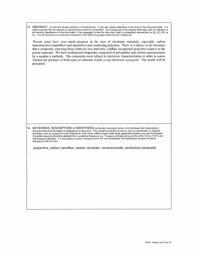
Abstract Recent years have seen much progress in the area of electronic materials, especially carbon nanostructures (nanofibers and nanotubes) and conducting polymers. There is evidence in the literature that a composite, marrying these relatively new materials, exhibits exceptional properties relative to the parent materials. We have synthesized composites comprised of polyaniline and carbon nanostructures by a number a methods. The composites were subject to electronic characterization in order to assess whether the presence of both types of materials results in any electronic synergism. The results will be presented.
Résumé
Les dernières années ont vu beaucoup de progrès dans le secteur des matériaux électroniques, en particulier les nanostructures (nanofibres et nanotubes) et des polymères conducteurs. La littérature semble prouver qu’un composite associant ces matériaux relativement nouveaux présente des propriétés exceptionnelles par rapport aux matériaux parents. Nous avons synthétisé par un certain nombre de méthodes des composites comprenant des nanostructures de polyaniline et de carbone. Les composites étaient soumis à une caractérisation électronique afin de déterminer si la présence des deux types de matériau produisait une synergie électronique. Les résultats sont présentés.
DRDC Atlantic TM 2003-206 i

This page intentionally left blank.
ii DRDC Atlantic TM 2003-206
Executive summary
Introduction
Two relatively new materials, carbon nanotubes and conducting polymers, have been the focus of much research of late. Interest in these materials is largely due to their electrical conductivity, although the nanotubes are also the focus of many structural studies as a result of their mechanical strength. Although they both exhibit good electrical properties, each one also possesses shortcomings. A composite promises to be interesting as the strengths of each are complementary. Most notably, the mechanical strength and thermal properties of the carbon may help to improve the strength and environmental integrity of the conducting polymers. In addition, the aggregation tendency and poor matrix adhesion of the carbon, may be addressed by the presence of the polymer.
Results
Polyaniline-carbon nanotube and polyaniline-carbon nanofibre composites have been prepared and the electrical conductivity measured. The composite conductivity values exhibit an enhancement over that of the parent materials.
Significance
The existence of a conductivity enhancement, in addition to improvement in environmental stability and mechanical properties, yields a composite that is greater than the sum of its parts. Such a composite would be of use in many areas that currently use conventional electrically conducting species (electrical components, displays, rechargeable batteries, sensors, etc.).
Future Plans
Further work into the preparation of these composites, as well as investigation into the nature of the conductivity enhancement is planned.
Huber, T.A., Diep, M.N.. 2003. Synthesis and Characterization of Polyaniline – Carbon Nanostructure Composites. DRDC Atlantic TM 2003-206.
DRDC Atlantic TM 2003-206 iii
Sommaire
Introduction
Deux matériaux relativement nouveaux, les nanotubes du carbone et les polymères conducteurs, ont constitué l’objet principal de beaucoup de recherches ces derniers temps. C’est leur conductivité électrique qui a attiré en grande partie l’intérêt sur ces matériaux. Ils présentent tous les deux de bonnes propriétés électriques, mais ils ont aussi chacun des défauts. Un composite promet d’être intéressant puisque les résistances de chacun des matériaux se complémentent. À noter en particulier que les propriétés mécaniques et thermiques du carbone peuvent contribuer à améliorer la résistance et l’intégrité environnementale des polymères conducteurs. De son côté, la présence du polymère peut traiter la tendance du carbone à l’agrégation et la faible adhésion à la matrice de celui-ci.
Résultats
Nous avons préparé des composites, nanotube polyaniline-carbone et nanofibre polyaniline-carbone, et mesuré leur conductivité électrique. Les valeurs de conductivité des composites présentent une amélioration par rapport à celles des matériaux parents.
Importance
Une conductivité accrue, renchérie par une stabilité environnementale et des propriétés mécaniques renforcées, rend un composite supérieur à la somme de ses éléments. Ce composite serait utile dans beaucoup de secteurs où l’on utilise actuellement les genres de conducteurs électriques conventionnels (composants électriques, visualisation électrique, piles électriques rechargeables, capteurs électriques, etc.)
Futurs plans
Nous envisageons de continuer à travailler à la préparation de ces composites ainsi qu’à fouiller la nature de l’amélioration de la conductivité.
Huber, T.A., Diep, M.N.. 2003. Synthesis and Characterization of Polyaniline – Carbon Nanostructure Composites. DRDC Atlantic TM 2003-206 R & D pour la défense Canada – Atlantique.
iv DRDC Atlantic TM 2003-206
Table of contents
Abstract........................................................................................................................................ i
Résumé ........................................................................................................................................ i
Executive summary ................................................................................................................... iii
Sommaire................................................................................................................................... iv
Table of contents ........................................................................................................................ v
List of figures ............................................................................................................................ vi
List of tables .............................................................................................................................. vi
Introduction ................................................................................................................................ 1
Experimental............................................................................................................................... 2 Method I (bulk solution)................................................................................................ 2 Method II (isolation of solid)......................................................................................... 2
Results and Discussion ............................................................................................................... 3 Polyaniline – Nanotube (PAni/DBSA/NT) Composites – Method I............................. 3 Polyaniline – Nanotube (PAni/DBSA/NT) Composites – Method II............................ 4 Polyaniline – Nanotube (PAni/DBSA/NT) Composites – Ex-Situ ................................ 5 Polyaniline – Nanofiber (PAni/DBSA/CNF) Composites – Method I.......................... 5 Polyaniline – Nanofiber (PAni/DBSA/CNF) Composites – Method II ........................ 7 Polyaniline – Nanofiber (PAni/DBSA/CNF) Composites – Ex-Situ............................. 9
Conclusion................................................................................................................................ 11
References ................................................................................................................................ 12
List of symbols/abbreviations/acronyms/initialisms ................................................................ 13
Distribution list ......................................................................................................................... 14
DRDC Atlantic TM 2003-206 v
List of figures
Figure 1. A Plot of Conductivity as a Function of Nanotube Content........................................ 4
Figure 2. A Plot of Composite Conductivity Versus Wt % Carbon Nanofibers ........................ 6
List of tables
Table 1. Conductivity Data of PAni/DBSA/NT Composites (Method I)................................... 3
Table 2. Conductivity Data of PAni/DBSA/CNF Composites................................................... 6
Table 3. Conductivity and Yield Data for PAni/DBSA/CNF composites (Method II – variable CNF).................................................................................................................................... 8
Table 4. Conductivity and Yield Data for PAni/DBSA/CNF composites (Method II – variable aniline)................................................................................................................................. 9
Table5. Conductivity and Content of Isolated Solid ................................................................ 10
vi DRDC Atlantic TM 2003-206
Introduction
Carbon nanotubes and conducting polymers have been the focus of much research in the last decade or so. The former have been the subject of much scrutiny due to their extraordinary electrical and mechanical properties, and the latter because of their exceptional electrical properties. Both materials have been investigated for their potential as electronic or optical devices.
Despite their exceptional properties, each material has shortcomings. Carbon nanotubes are expensive, exhibit poor matrix adhesion, and tend to aggregate, which makes processing challenging. Conducting polymers exhibit poor mechanical properties, and are subject to environmental degradation over time.
A composite made up of these two materials would be highly interesting, as the shortcomings of one material may be addressed by the presence of the other. Coating the nanotubes with a conducting polymer should reduce the degree of aggregation, thus improve matrix adhesion and processibility. Moreover, conducting polymers are far more economical to produce, thereby reducing the overall cost per device, or per unit mass. The presence of carbon nanotubes in such a composite would likely improve mechanical properties, due to their high strength, as well as help to maintain the integrity of the composite due to their thermal strength and potential antioxidant behaviour.
Over and above the potential mutually beneficial outcome, there have been reports of interesting electronic interaction between these two materials [1-4]. In addition to reports of potential electronic synergy, there are other findings that suggest that there is no electronic interaction between conducting polymers and nanotubes [5-7].
In this paper we report the preparation and characterization of both polyaniline-carbon nanotube and polyaniline-carbon nanofiber composites. The composites were prepared by both in-situ polymerization (aniline was polymerized in the presence of the nanostructure) and ex-situ polymerization (the nanostructure was mixed with the pre-formed polyaniline). In an effort to investigate the discrepancy in the literature, the electronic properties of the composites were probed by measuring the conductivity of the bulk product.
DRDC Atlantic TM 2003-206 1
Experimental
Aniline (Aldrich, > 99.5%) was distilled under vacuum before use; dodecylbenzenesulfonic acid (DBSA) (Aldrich, 70 wt% solution in 2-propanol), multiwalled nanotubes (Aldrich, > 95%), toluene (Aldrich, > 99.5 %), and ammonium persulfate (APS) (Fisher Scientific, 99%) were used as received. The carbon nanofibers (Pyrograf III carbon fibers, grade PR-24-PS-LD) were ball-milled before use.
Conductivity of pressed pellets (13 mm diameter, 8 tons, thickness ca. 1 mm) was performed using the four-point probe method.
The polyaniline – nanostructure composites were prepared by both in-situ and ex-situ polymerization. For both the nanotube and the nanofiber composites, the products were prepared in toluene solution containing DBSA (0.06 M), but two slightly different methods for isolation were employed (vide infra). The ex-situ polymerization simply consists of sonicating the carbon nanostructures in a toluene solution of PAni/DBSA, followed by stirring overnight.
Method I (bulk solution)
In one set of in-situ experiments, the nanotubes were dispersed in toluene containing aniline by high frequency, low power sonication (12W, 55kHz) for approximately two hours. The APS was dissolved in ~ 10 mL of water and slowly added dropwise to the toluene suspension with stirring. After addition was complete the reaction was allowed to stir overnight to ensure completion of reaction. The reaction mixture was transferred to a separatory funnel, and the organic layer was washed twice with ~ 20 mL of a 1:1 acetone:water mixture in order to remove excess DBSA and reaction by-products. The toluene was allowed to evaporate from the organic layer (which contains the nanostructures and PAni/DBSA). The residue was then washed with ethanol, and dried in vacuo at room temperature for at least 24 hours. After drying, conductivity measurements were performed on pressed pellets of the product.
Method II (isolation of solid)
This method is similar to Method I up to and including washing the organic layer with the acetone:water mixture. After washing, the organic layer was filtered through a track-etched polycarbonate membrane (Millipore, 0.2 micron diameter pores) to collect the solid; the toluene was allowed to evaporate from the filtrate, and the residue was washed, and dried as above.
2 DRDC Atlantic TM 2003-206
Results and Discussion
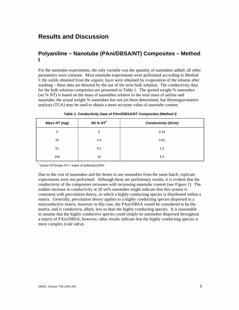
Polyaniline – Nanotube (PAni/DBSA/NT) Composites – Method I
For the nanotube experiments, the only variable was the quantity of nanotubes added; all other parameters were constant. Most nanotube experiments were performed according to Method I; the solids obtained from the organic layer were obtained by evaporation of the toluene after washing – these data are denoted by the use of the term bulk solution. The conductivity data for the bulk solution composites are presented in Table 1. The quoted weight % nanotubes (wt % NT) is based on the mass of nanotubes relative to the total mass of aniline and nanotube; the actual weight % nanotubes has not yet been determined, but thermogravimetric analysis (TGA) may be used to obtain a more accurate value of nanotube content.
Table 1. Conductivity Data of PAni/DBSA/NT Composites (Method I)
Mass NT (mg) Wt % NT‡ Conductivity (S/cm)
0 0 0.34
25 4.6 0.62
51 9.1 1.5
100 16 6.3
‡ (mass NT/(mass NT + mass of aniline))x100%
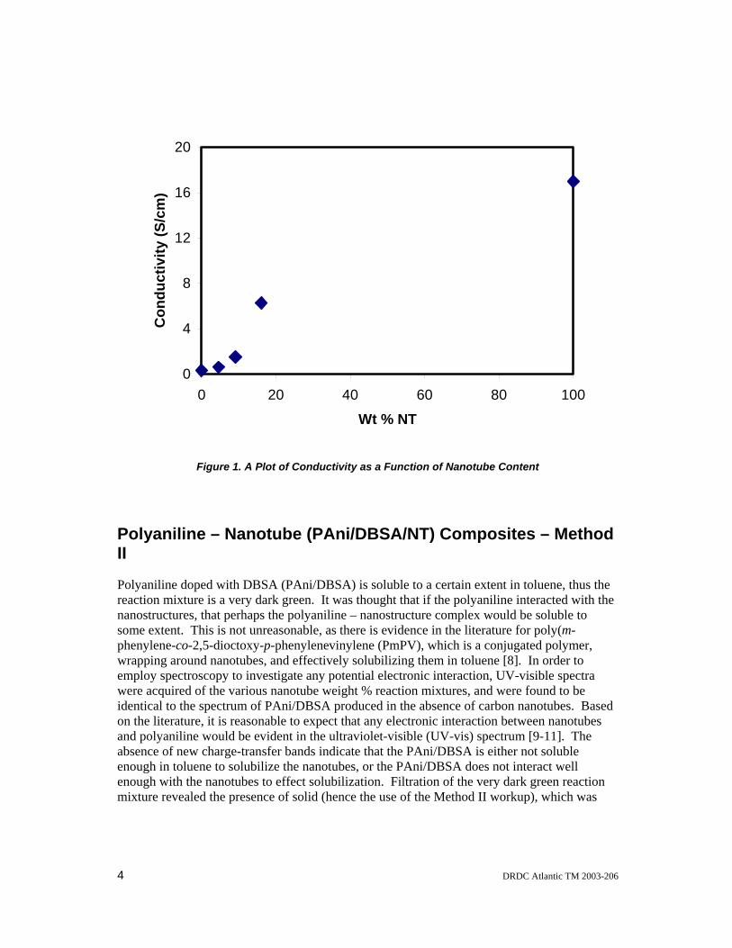
Due to the cost of nanotubes and the desire to use nanotubes from the same batch, replicate experiments were not performed. Although these are preliminary results, it is evident that the conductivity of the composites increases with increasing nanotube content (see Figure 1). The sudden increase in conductivity at 20 wt% nanotubes might indicate that this system is consistent with percolation theory, in which a highly conducting species is distributed within a matrix. Generally, percolation theory applies to a highly conducting species dispersed in a nonconductive matrix, however in this case, the PAni/DBSA would be considered to be the matrix, and is conductive, albeit, less so than the highly conducting species. It is reasonable to assume that the highly conductive species could simply be nanotubes dispersed throughout a matrix of PAni/DBSA, however, other results indicate that the highly conducting species is more complex (vide infra).
DRDC Atlantic TM 2003-206 3
0
4
8
12
16
20
0 20 40 60 80 100Wt % NT
Con
duct
ivity
(S/c
m)
Figure 1. A Plot of Conductivity as a Function of Nanotube Content
Polyaniline – Nanotube (PAni/DBSA/NT) Composites – Method II
Polyaniline doped with DBSA (PAni/DBSA) is soluble to a certain extent in toluene, thus the reaction mixture is a very dark green. It was thought that if the polyaniline interacted with the nanostructures, that perhaps the polyaniline – nanostructure complex would be soluble to some extent. This is not unreasonable, as there is evidence in the literature for poly(m-phenylene-co-2,5-dioctoxy-p-phenylenevinylene (PmPV), which is a conjugated polymer, wrapping around nanotubes, and effectively solubilizing them in toluene [8]. In order to employ spectroscopy to investigate any potential electronic interaction, UV-visible spectra were acquired of the various nanotube weight % reaction mixtures, and were found to be identical to the spectrum of PAni/DBSA produced in the absence of carbon nanotubes. Based on the literature, it is reasonable to expect that any electronic interaction between nanotubes and polyaniline would be evident in the ultraviolet-visible (UV-vis) spectrum [9-11]. The absence of new charge-transfer bands indicate that the PAni/DBSA is either not soluble enough in toluene to solubilize the nanotubes, or the PAni/DBSA does not interact well enough with the nanotubes to effect solubilization. Filtration of the very dark green reaction mixture revealed the presence of solid (hence the use of the Method II workup), which was
4 DRDC Atlantic TM 2003-206
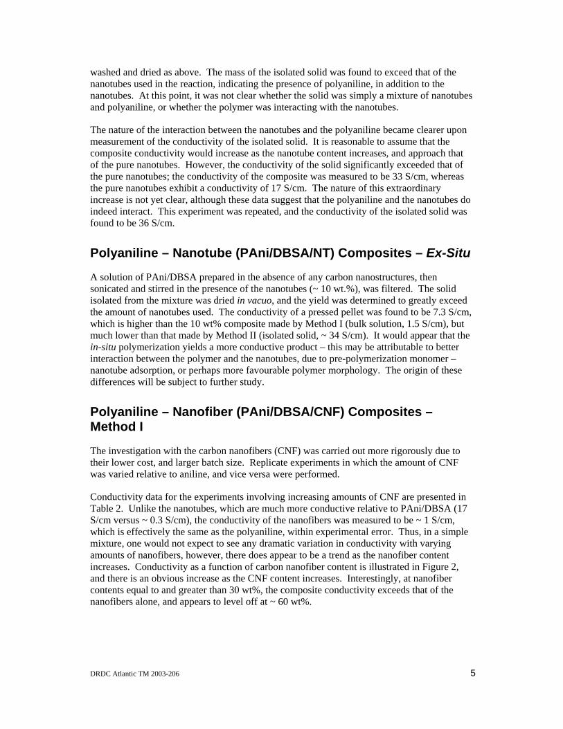
washed and dried as above. The mass of the isolated solid was found to exceed that of the nanotubes used in the reaction, indicating the presence of polyaniline, in addition to the nanotubes. At this point, it was not clear whether the solid was simply a mixture of nanotubes and polyaniline, or whether the polymer was interacting with the nanotubes.
The nature of the interaction between the nanotubes and the polyaniline became clearer upon measurement of the conductivity of the isolated solid. It is reasonable to assume that the composite conductivity would increase as the nanotube content increases, and approach that of the pure nanotubes. However, the conductivity of the solid significantly exceeded that of the pure nanotubes; the conductivity of the composite was measured to be 33 S/cm, whereas the pure nanotubes exhibit a conductivity of 17 S/cm. The nature of this extraordinary increase is not yet clear, although these data suggest that the polyaniline and the nanotubes do indeed interact. This experiment was repeated, and the conductivity of the isolated solid was found to be 36 S/cm.
Polyaniline – Nanotube (PAni/DBSA/NT) Composites – Ex-Situ
A solution of PAni/DBSA prepared in the absence of any carbon nanostructures, then sonicated and stirred in the presence of the nanotubes (~ 10 wt.%), was filtered. The solid isolated from the mixture was dried in vacuo, and the yield was determined to greatly exceed the amount of nanotubes used. The conductivity of a pressed pellet was found to be 7.3 S/cm, which is higher than the 10 wt% composite made by Method I (bulk solution, 1.5 S/cm), but much lower than that made by Method II (isolated solid, ~ 34 S/cm). It would appear that the in-situ polymerization yields a more conductive product – this may be attributable to better interaction between the polymer and the nanotubes, due to pre-polymerization monomer – nanotube adsorption, or perhaps more favourable polymer morphology. The origin of these differences will be subject to further study.
Polyaniline – Nanofiber (PAni/DBSA/CNF) Composites – Method I
The investigation with the carbon nanofibers (CNF) was carried out more rigorously due to their lower cost, and larger batch size. Replicate experiments in which the amount of CNF was varied relative to aniline, and vice versa were performed.
Conductivity data for the experiments involving increasing amounts of CNF are presented in Table 2. Unlike the nanotubes, which are much more conductive relative to PAni/DBSA (17 S/cm versus ~ 0.3 S/cm), the conductivity of the nanofibers was measured to be ~ 1 S/cm, which is effectively the same as the polyaniline, within experimental error. Thus, in a simple mixture, one would not expect to see any dramatic variation in conductivity with varying amounts of nanofibers, however, there does appear to be a trend as the nanofiber content increases. Conductivity as a function of carbon nanofiber content is illustrated in Figure 2, and there is an obvious increase as the CNF content increases. Interestingly, at nanofiber contents equal to and greater than 30 wt%, the composite conductivity exceeds that of the nanofibers alone, and appears to level off at ~ 60 wt%.
DRDC Atlantic TM 2003-206 5
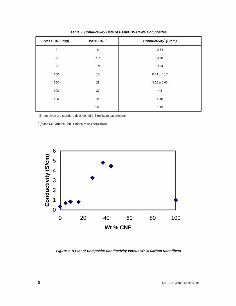
Table 2. Conductivity Data of PAni/DBSA/CNF Composites
Mass CNF (mg) Wt % CNF‡ Conductivity* (S/cm)
0 0 0.34
25 4.7 0.68
50 8.9 0.84
100 16 0.81 ± 0.17
200 28 3.26 ± 0.03
300 37 4.8
400 44 4.45
100 1.13
* Errors given are standard deviation of 2-3 replicate experiments
‡ (mass CNF/(mass CNF + mass of aniline))x100%
0
1
2
3
4
5
6
0 20 40 60 80 10Wt % CNF
Con
duct
ivity
(S/c
m)
0
Figure 2. A Plot of Composite Conductivity Versus Wt % Carbon Nanofibers
6 DRDC Atlantic TM 2003-206
It is not unusual for conductivity values to vary for reaction products prepared identically, or even for samples from the same synthetic batch; the variation may be as high as 1 – 2 S/cm, although the PAni/DBSA conductivity values appear to be consistently between 0.25 and 0.5 S/cm, even under varying DBSA concentration (0.03 – 1.0 M), and therefore varying pH. In addition, several measurements of the CNFs consistently yield conductivities of 1.1 ± 0.1 S/cm. This, in conjunction with the consistence of the PAni/DBSA conductivities, would suggest that the conductivity values for the high % nanofiber composites (30 – 80 %) are statistically significant.
Polyaniline – Nanofiber (PAni/DBSA/CNF) Composites – Method II
Two sets of experiments were performed using the Method II procedure, in which the solid product was isolated from the dissolved PAni/DBSA. In the first set, the amount of CNFs was varied, and in the second set, the aniline was varied.
In the first set, the amount of aniline, and therefore aniline concentration, was constant (0.055 M). Conductivity results for these experiments are presented in Table 3. As the amount of CNF increases, there appears to be little effect on the conductivity of the isolated solid – varying the weight % CNF from 9 to 44, yielded isolated solids having conductivity within a fairly narrow range (5.4 ± 0.8 S/cm). In addition, the conductivity of the products obtained from each reaction mixture filtrate falls within the expected range of 0.25 to 0.5 S/cm for PAni/DBSA (0.3 ± 0.1 S/cm). Based on the conductivity, it would appear that the solid isolated in each experiment is of comparable composition. This is in contrast to the composites obtained by precipitation of all products (bulk solution, Table 2), in which the conductivity increases with increasing nanofiber mass. Since the isolated solids contain polyaniline, this method was performed in the absence of any carbon nanostructures in order to rule out the possibility that the polyaniline is simply an insoluble, high molecular weight, and therefore more conductive fraction. Several pellets of PAni/DBSA prepared by this method were pressed and the conductivity was found to be 1.2 ± 0.6 S/cm.
DRDC Atlantic TM 2003-206 7
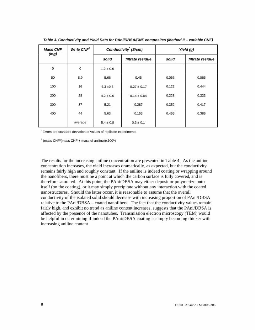
Table 3. Conductivity and Yield Data for PAni/DBSA/CNF composites (Method II – variable CNF)
Conductivity* (S/cm) Yield (g) Mass CNF (mg)
Wt % CNF‡
solid filtrate residue solid filtrate residue
0 0 1.2 ± 0.6
50 8.9 5.66 0.45 0.065 0.065
100 16 6.3 ±0.8 0.27 ± 0.17 0.122 0.444
200 28 4.2 ± 0.6 0.14 ± 0.04 0.228 0.333
300 37 5.21 0.287 0.352 0.417
400 44 5.63 0.153 0.455 0.386
average 5.4 ± 0.8 0.3 ± 0.1
* Errors are standard deviation of values of replicate experiments
‡ (mass CNF/(mass CNF + mass of aniline))x100%
The results for the increasing aniline concentration are presented in Table 4. As the aniline concentration increases, the yield increases dramatically, as expected, but the conductivity remains fairly high and roughly constant. If the aniline is indeed coating or wrapping around the nanofibers, there must be a point at which the carbon surface is fully covered, and is therefore saturated. At this point, the PAni/DBSA may either deposit or polymerize onto itself (on the coating), or it may simply precipitate without any interaction with the coated nanostructures. Should the latter occur, it is reasonable to assume that the overall conductivity of the isolated solid should decrease with increasing proportion of PAni/DBSA relative to the PAni/DBSA – coated nanofibers. The fact that the conductivity values remain fairly high, and exhibit no trend as aniline content increases, suggests that the PAni/DBSA is affected by the presence of the nanotubes. Transmission electron microscopy (TEM) would be helpful in determining if indeed the PAni/DBSA coating is simply becoming thicker with increasing aniline content.
8 DRDC Atlantic TM 2003-206
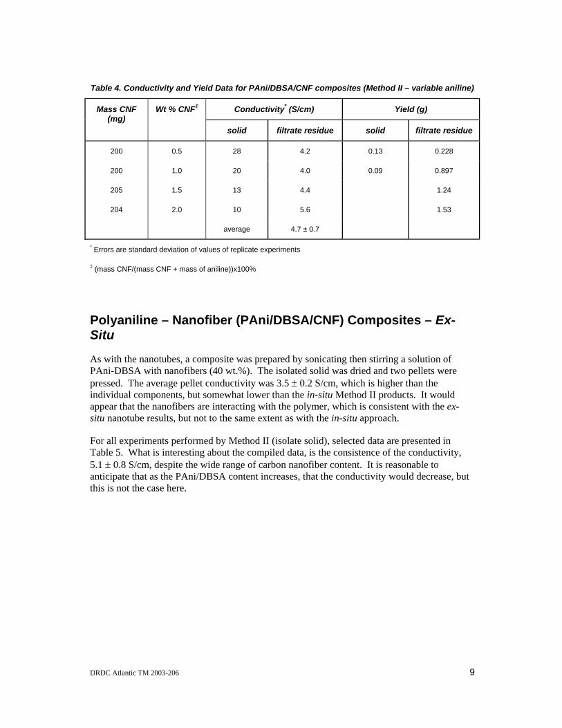
Table 4. Conductivity and Yield Data for PAni/DBSA/CNF composites (Method II – variable aniline)
Conductivity* (S/cm) Yield (g) Mass CNF (mg)
Wt % CNF‡
solid filtrate residue solid filtrate residue
200 0.5 28 4.2 0.13 0.228
200 1.0 20 4.0 0.09 0.897
205 1.5 13 4.4 1.24
204 2.0 10 5.6 1.53
average 4.7 ± 0.7
* Errors are standard deviation of values of replicate experiments
‡ (mass CNF/(mass CNF + mass of aniline))x100%
Polyaniline – Nanofiber (PAni/DBSA/CNF) Composites – Ex-Situ
As with the nanotubes, a composite was prepared by sonicating then stirring a solution of PAni-DBSA with nanofibers (40 wt.%). The isolated solid was dried and two pellets were pressed. The average pellet conductivity was 3.5 ± 0.2 S/cm, which is higher than the individual components, but somewhat lower than the in-situ Method II products. It would appear that the nanofibers are interacting with the polymer, which is consistent with the ex-situ nanotube results, but not to the same extent as with the in-situ approach.
For all experiments performed by Method II (isolate solid), selected data are presented in Table 5. What is interesting about the compiled data, is the consistence of the conductivity, 5.1 ± 0.8 S/cm, despite the wide range of carbon nanofiber content. It is reasonable to anticipate that as the PAni/DBSA content increases, that the conductivity would decrease, but this is not the case here.
DRDC Atlantic TM 2003-206 9
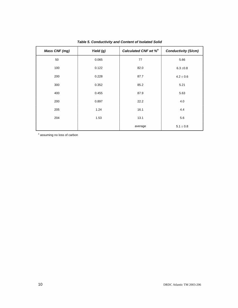
Table 5. Conductivity and Content of Isolated Solid
Mass CNF (mg) Yield (g) Calculated CNF wt %a Conductivity (S/cm)
50 0.065 77 5.66
100 0.122 82.0 6.3 ±0.8
200 0.228 87.7 4.2 ± 0.6
300 0.352 85.2 5.21
400 0.455 87.9 5.63
200 0.897 22.2 4.0
205 1.24 16.1 4.4
204 1.53 13.1 5.6
average 5.1 ± 0.8
a assuming no loss of carbon
10 DRDC Atlantic TM 2003-206
Conclusion These results, although preliminary, suggest the formation of a highly conducting polyaniline – carbon nanostructure composite, whose conductivity exceeds that of both components individually. The nature of this electrical enhancement is not clear, but there are several possibilities. The enhancement may be due to a templating effect of the nanostructure, in which the organization of the aniline prior to polymerization results in a more favourable morphology. Alternatively, as has been suggested in the literature, the presence of a synergistic electrical interaction between the conducting polymer and the nanostructure (and/or residual impurities in the nanostructure) could result in conductivity enhancement. Lastly, the increased electrical interaction between the two components could simply result from the formation of a more efficient composite, perhaps due to greater electrical contact between the carbon nanostructures via polyaniline chains.
DRDC Atlantic TM 2003-206 11
References 1. Musa, I., Baxendale, M., Amaratunga, G.A.J., Eccleston, W., Properties of
Regioregular poly(3-octylthiophene)/multi-wall carbon nanotube composites. Synth. Met., 1999. 102: p. 1250.
2. Woo, H.S., Czerw, R., Webster, S., Carroll, D.L., Park, J.W., Lee, J.H., Organic light emitting diodes fabricated with single wall carbon nanotubes dispersed in a hole conducting buffer: the role of carbon nanotubes in a hole conducting polymer. Synth. Met., 2001. 116: p. 369-372.
3. Cochet, M., Maser, W.K., Benito, A.M., Callejas, M.A., Martinez, M.T., Benoit, J.M., Schreiber, J., Chauvet, O., Synthesis of a new polyaniline/nanotube composite: "in-situ" polymerisation and charge transfer through site-selective interaction. Chem. Commun., 2001: p. 1450-1451.
4. Maser, W.K., Benito, A.M., Callejas, M.A., Seeger, T., Martinez, M.T., Schreiber, J., Muszynski, J., Chauvet, O., Osvath, Z., Koos, A.A., Biro, L.P., Synthesis and characterization of new polyaniline/nanotube composites. Mat. Sci. & Eng. C, 2003. 23: p. 87-91.
5. Fan, J., Wan, M., Zhu, D., Chang, B., Pan, Z., Xie, S., Synthesis and properties of carbon nanotube-polypyrrole composites. Synth. Met., 1999. 102: p. 1266-1267.
6. Deng, J., Ding, X., Zhang, W., Peng, Y., Wang, J., Long, X., Li, P., Chan, A.S.C., Carbon nanotube-polyaniline hybrid materials. Eur. Polym. J., 2002. 38: p. 2497-2501.
7. Feng, W., Bai, X.D., Lian, Y.Q., Liang, J., Wang, X.G., Yoshino, K., Well-aligned polyaniline/carbon-nanotube composite films grown by in-situ aniline polymerization. Carbon, 2003. 41: p. 1551-1557.
8. Coleman, J.N., O'Brien, D.F., in het Panhuis, M., Dalton, A.B., McCarthy, B., Barklie, R.C., Blau, W.J., Solubility of nanotubes in arc discharge carbon powder. Synth. Met, 2001. 121: p. 1229-1230.
9. McCarthy, B., Dalton, A.B., Coleman, J.N., Byrne, H.J., Bernier, P., Blau, W.J., Spectroscopic investigation of conjugated polymer/single-walled carbon nanotube interactions. Chem. Phys. Lett., 2001. 350: p. 27-32.
10. Sun, Y., Wilson, S.R., Schuster, D.I., High Dissolution and Strong Light Emission of Carbon Nanotubes in Aromatic Amine Solvents. J. Am. Chem. Soc., 2001. 123: p. 5348 - 5349.
11. Zhang, J., Lee, J.-K., Wu, Y., Murray, R.W., Photoluminescence and Electronic Interaction of Anthracene Derivatives Adsorbed on Sidewalls of Single-Walled Carbon Nanotubes. Nano Lett., 2003. 3: p. 403-407.
DRDC Atlantic TM 2003-206 12
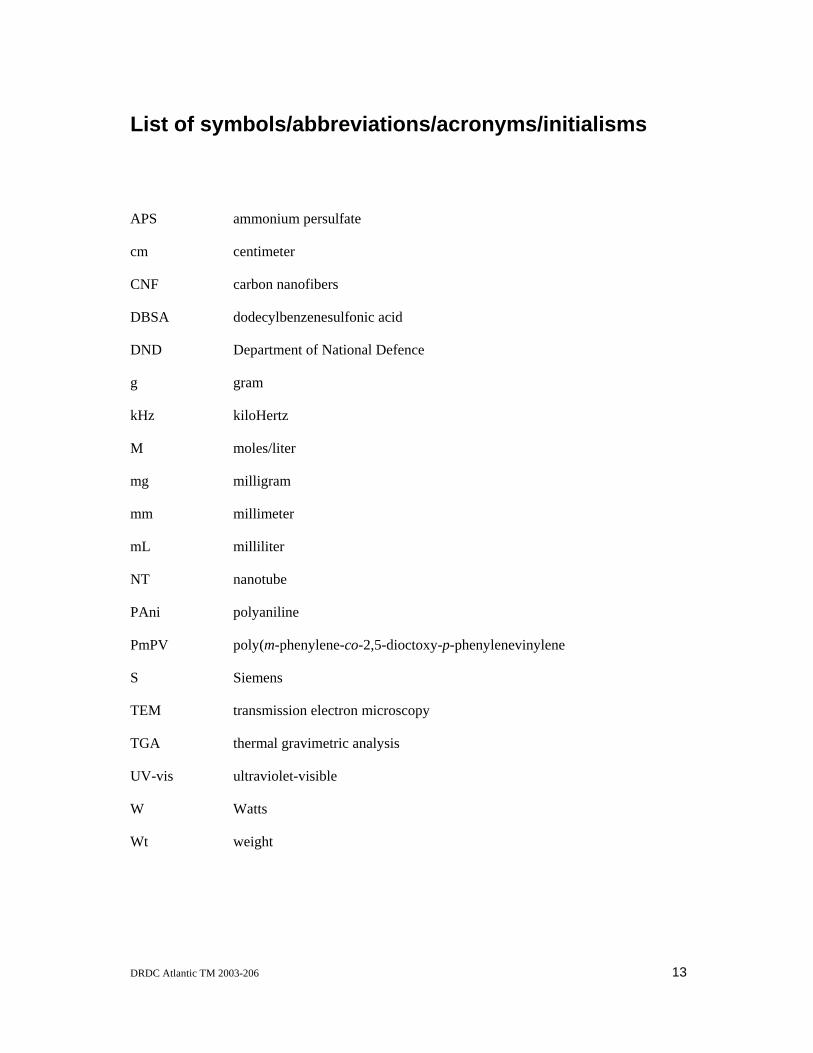
List of symbols/abbreviations/acronyms/initialisms
APS ammonium persulfate
cm centimeter
CNF carbon nanofibers
DBSA dodecylbenzenesulfonic acid
DND Department of National Defence
g gram
kHz kiloHertz
M moles/liter
mg milligram
mm millimeter
mL milliliter
NT nanotube
PAni polyaniline
PmPV poly(m-phenylene-co-2,5-dioctoxy-p-phenylenevinylene
S Siemens
TEM transmission electron microscopy
TGA thermal gravimetric analysis
UV-vis ultraviolet-visible
W Watts
Wt weight
DRDC Atlantic TM 2003-206 13
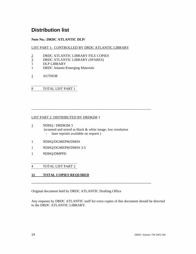
Distribution list Note No.: DRDC ATLANTIC DLP/ LIST PART 1: CONTROLLED BY DRDC ATLANTIC LIBRARY 2 DRDC ATLANTIC LIBRARY FILE COPIES 3 DRDC ATLANTIC LIBRARY (SPARES) 1 DLP LIBRARY 1 DRDC Atlantic/Emerging Materials 1 AUTHOR 8 TOTAL LIST PART 1
------------------------------------------------------------------------------------------------------ LIST PART 2: DISTRIBUTED BY DRDKIM 3 1 NDHQ / DRDKIM 3 (scanned and stored as black & white image, low resolution
- laser reprints available on request ) 1 NDHQ/DGMEPM/DMSS
1 NDHQ/DGMEPM/DMSS 3-5
1 NDHQ/DMPPD 4 TOTAL LIST PART 2 12 TOTAL COPIES REQUIRED ------------------------------------------------------------------------------------------------------ Original document held by DRDC ATLANTIC Drafting Office
Any requests by DRDC ATLANTIC staff for extra copies of this document should be directed to the DRDC ATLANTIC LIBRARY.
14 DRDC Atlantic TM 2003-206

This page intentionally left blank.