Embed Size (px)
Citation preview
TECHNICALREPORT – TYPE 3
IEC61366-4
First edition1998-03
Hydraulic turbines, storage pumpsand pump-turbines –Tendering Documents –
Part 4:Guidelines for technical specificationsfor Kaplan and propeller turbines
Turbines hydrauliques, pompes d’accumulationet pompes-turbines –Documents d’appel d’offres –
Partie 4:Guide des spécifications techniques pour les turbines Kaplanet les turbines à hélice
Commission Electrotechnique Internationale International Electrotechnical Commission PRICE CODE V
For price, see current catalogue
IEC 1998 Copyright - all rights reserved
No part of this publication may be reproduced or utilized in any form or by any means, electronic ormechanical, including photocopying and microfilm, without permission in writing from the publisher.
International Electrotechnical Commission 3, rue de Varembé Geneva, SwitzerlandTelefax: +41 22 919 0300 e-mail: [email protected] IEC web site http: //www.iec.ch
– 2 – 61366-4 © IEC:1998(E)
CONTENTS
Page
FOREWORD ................................................................................................................... 4
Clause
0 Introduction to technical specifications ...................................................................... 7
1 Scope ....................................................................................................................... 9
2 Reference documents ............................................................................................... 9
3 Technical requirements............................................................................................. 9
3.1 Scope of work.................................................................................................. 9
3.2 Limits of the contract ....................................................................................... 10
3.3 Supply by Employer ......................................................................................... 10
3.4 Design conditions ............................................................................................ 11
3.5 Technical performance and other guarantees................................................... 14
3.6 Mechanical design criteria ............................................................................... 17
3.7 Design documentation ..................................................................................... 17
3.8 Materials and construction ............................................................................... 18
3.9 Shop inspection and testing ............................................................................. 19
4 Technical specifications for fixed/embedded components .......................................... 20
4.1 Spiral case ...................................................................................................... 21
4.2 Stay ring .......................................................................................................... 22
4.3 Foundation ring ............................................................................................... 22
4.4 Discharge ring ................................................................................................. 23
4.5 Draft tube and draft tube liner .......................................................................... 23
4.6 Pit liner............................................................................................................ 24
5 Technical specifications for stationary/removable components .................................. 24
5.1 Headcover and bottom ring .............................................................................. 24
5.2 Guide vanes .................................................................................................... 25
6 Technical specifications for guide vane regulating apparatus ..................................... 25
6.1 Servomotors .................................................................................................... 25
6.2 Connecting rods .............................................................................................. 25
6.3 Regulating ring ................................................................................................ 26
6.4 Guide vane linkage .......................................................................................... 26
6.5 Guide vane overload protection........................................................................ 26
6.6 Locking devices ............................................................................................... 26
7 Technical specifications for rotating parts, guide bearings and seals ......................... 26
7.1 Runner ............................................................................................................ 26
7.2 Runner blade regulating apparatus .................................................................. 27
7.3 Main shaft ....................................................................................................... 27
7.4 Turbine guide bearing ...................................................................................... 28
61366-4 © IEC:1998(E) – 3 –
Clause Page
7.5 Main shaft seal ................................................................................................ 28
7.6 Standstill (maintenance) seal ........................................................................... 28
8 Technical specifications for thrust bearing (when specified as part ofturbine supply) .......................................................................................................... 29
8.1 Design data .............................................................................................................. 29
8.2 Bearing support ........................................................................................................ 29
8.3 Bearing assembly ..................................................................................................... 29
8.4 Oil injection pressure lift system................................................................................ 29
9 Technical specifications for miscellaneous components ............................................ 29
9.1 Walkways, access platforms and stairs ............................................................ 29
9.2 Lifting fixtures .................................................................................................. 30
9.3 Special tools .................................................................................................... 30
9.4 Standard tools ................................................................................................. 30
9.5 Turbine pit hoist............................................................................................... 30
9.6 Nameplate ....................................................................................................... 30
10 Technical specifications for auxiliary systems............................................................ 30
10.1 Turbine pit drainage......................................................................................... 30
10.2 Lubrication of guide vane regulating system ..................................................... 31
10.3 Air admission system ....................................................................................... 31
10.4 Tailwater depression system ............................................................................ 31
11 Technical specifications for instrumentation .............................................................. 31
11.1 Controls........................................................................................................... 31
11.2 Indication......................................................................................................... 31
11.3 Protection ........................................................................................................ 31
12 Spare parts............................................................................................................... 32
13 Model acceptance tests ............................................................................................ 32
14 Site installation and commissioning tests .................................................................. 33
14.1 General ........................................................................................................... 33
14.2 Installation procedures..................................................................................... 33
14.3 Tests during installation ................................................................................... 33
14.4 Commissioning tests........................................................................................ 33
15 Field acceptance tests .............................................................................................. 34
15.1 Scope and reports ........................................................................................... 34
15.2 Inspection of cavitation pitting .......................................................................... 34
– 4 – 61366-4 © IEC:1998(E)
INTERNATIONAL ELECTROTECHNICAL COMMISSION____________
HYDRAULIC TURBINES, STORAGE PUMPS AND PUMP-TURBINES –TENDERING DOCUMENTS –
Part 4: Guidelines for technical specificationsfor Kaplan and propeller turbines
FOREWORD
1) The IEC (International Electrotechnical Commission) is a worldwide organization for standardization comprisingall national electrotechnical committees (IEC National Committees). The object of the IEC is to promoteinternational co-operation on all questions concerning standardization in the electrical and electronic fields. Tothis end and in addition to other activities, the IEC publishes International Standards. Their preparation isentrusted to technical committees; any IEC National Committee interested in the subject dealt with mayparticipate in this preparatory work. International, governmental and non-governmental organizations liaisingwith the IEC also participate in this preparation. The IEC collaborates closely with the International Organizationfor Standardization (ISO) in accordance with conditions determined by agreement between the twoorganizations.
2) The formal decisions or agreements of the IEC on technical matters express, as nearly as possible, aninternational consensus of opinion on the relevant subjects since each technical committee has representationfrom all interested National Committees.
3) The documents produced have the form of recommendations for international use and are published in the formof standards, technical reports or guides and they are accepted by the National Committees in that sense.
4) In order to promote international unification, IEC National Committees undertake to apply IEC InternationalStandards transparently to the maximum extent possible in their national and regional standards. Anydivergence between the IEC Standard and the corresponding national or regional standard shall be clearlyindicated in the latter.
5) The IEC provides no marking procedure to indicate its approval and cannot be rendered responsible for anyequipment declared to be in conformity with one of its standards.
6) Attention is drawn to the possibility that some of the elements of this International Standard may be the subjectof patent rights. The IEC shall not be held responsible for identifying any or all such patent rights.
The main task of IEC technical committees is to prepare International Standards. Inexceptional circumstances, a technical committee may propose the publication of a technicalreport of one of the following types:
• type 1, when the required support cannot be obtained for the publication of an InternationalStandard, despite repeated efforts;
• type 2, when the subject is still under technical development or where for any other reasonthere is the future but no immediate possibility of an agreement on an InternationalStandard;
• type 3, when a technical committee has collected data of a different kind from that which isnormally published as an International Standard, for example "state of the art".
Technical reports of types 1 and 2 are subject to review within three years of publication todecide whether they can be transformed into International Standards. Technical reports oftype 3 do not necessarily have to be reviewed until the data they provide are considered to beno longer valid or useful.
IEC 61366-4, which is a technical report of type 3, has been prepared by IEC technicalcommittee 4: Hydraulic turbines.
61366-4 © IEC:1998(E) – 5 –
The text of this technical report is based on the following documents:
Committee draft Report on voting
4/110/CDV 4/122/RVC
Full information on the voting for the approval of this technical report can be found in the reporton voting indicated in the above table.
Technical Report IEC 61366-4 is one of a series which deals with Tendering Documents forhydraulic turbines, storage pumps and pump-turbines. The series consists of seven parts:
Part 1: General and annexes (IEC 61366-1)
Part 2: Guidelines for technical specification for Francis turbines (IEC 61366-2)
Part 3: Guidelines for technical specification for Pelton turbines (IEC 61366-3)
Part 4: Guidelines for technical specification for Kaplan and propeller turbines (IEC 61366-4)
Part 5: Guidelines for technical specification for tubular turbines (IEC 61366-5)
Part 6: Guidelines for technical specification for pump-turbines (IEC 61366-6)
Part 7: Guidelines for technical specification for storage pumps (IEC 61366-7)
Parts 2 to 7 are "stand-alone" publications which when used with Part 1 contain guidelines for aspecific machine type (i.e. Parts 1 and 4 represent the combined guide for Kaplan andpropeller turbines). A summary of the proposed contents for a typical set of TenderingDocuments is given in the following table 1 and annex A. Table 1 summarizes the arrangementof each part of this guide and serves as a reference for the various chapters and sections ofthe Tendering Documents (see 3.2 of this part).
A bilingual edition of this technical report may be issued at a later date.
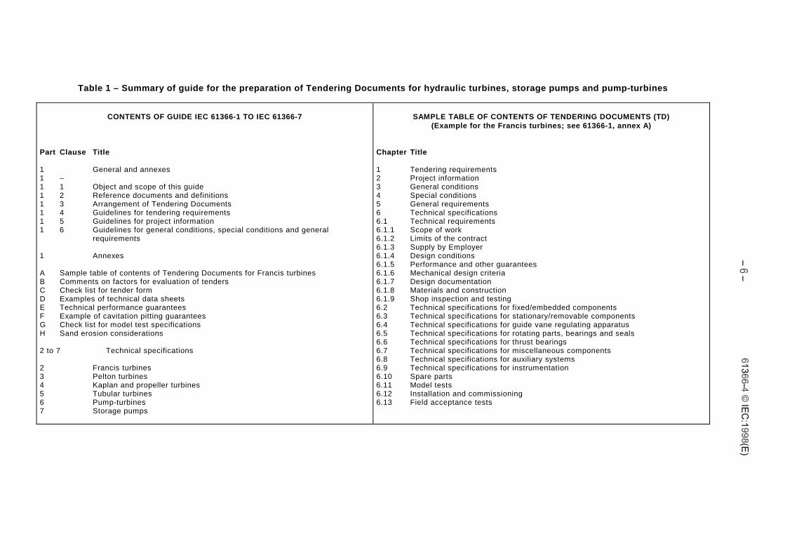
Table 1 – Summary of guide for the preparation of Tendering Documents for hydraulic turbines, storage pumps and pump-turbines
CONTENTS OF GUIDE IEC 61366-1 TO IEC 61366-7 SAMPLE TABLE OF CONTENTS OF TENDERING DOCUMENTS (TD)(Example for the Francis turbines; see 61366-1, annex A)
Part Clause Title
1 General and annexes1 –1 1 Object and scope of this guide1 2 Reference documents and definitions1 3 Arrangement of Tendering Documents1 4 Guidelines for tendering requirements1 5 Guidelines for project information1 6 Guidelines for general conditions, special conditions and general
requirements
1 Annexes
A Sample table of contents of Tendering Documents for Francis turbinesB Comments on factors for evaluation of tendersC Check list for tender formD Examples of technical data sheetsE Technical performance guaranteesF Example of cavitation pitting guaranteesG Check list for model test specificationsH Sand erosion considerations
2 to 7 Technical specifications
2 Francis turbines3 Pelton turbines4 Kaplan and propeller turbines5 Tubular turbines6 Pump-turbines7 Storage pumps
Chapter Title
1 Tendering requirements2 Project information3 General conditions4 Special conditions5 General requirements6 Technical specifications6.1 Technical requirements6.1.1 Scope of work6.1.2 Limits of the contract6.1.3 Supply by Employer6.1.4 Design conditions6.1.5 Performance and other guarantees6.1.6 Mechanical design criteria6.1.7 Design documentation6.1.8 Materials and construction6.1.9 Shop inspection and testing6.2 Technical specifications for fixed/embedded components6.3 Technical specifications for stationary/removable components6.4 Technical specifications for guide vane regulating apparatus6.5 Technical specifications for rotating parts, bearings and seals6.6 Technical specifications for thrust bearings6.7 Technical specifications for miscellaneous components6.8 Technical specifications for auxiliary systems6.9 Technical specifications for instrumentation6.10 Spare parts6.11 Model tests6.12 Installation and commissioning6.13 Field acceptance tests
61366-4 © IEC:1998(E) – 7 –
HYDRAULIC TURBINES, STORAGE PUMPS AND PUMP-TURBINES –TENDERING DOCUMENTS –
Part 4: Guidelines for technical specificationsfor Kaplan and propeller turbines
0 Introduction to technical specifications
The main purpose of the technical specifications is to describe the specific technicalrequirements for the hydraulic machine for which the Tendering Documents (TD) are beingissued. To achieve clarity and to avoid confusion in contract administration, the Employershould not specify anything in the technical specifications which is of importance only to thepreparation of the tender. Such information and instructions should be given only in theinstructions to Tenderers (ITT). Accordingly, the ITT may refer to other chapters and sectionsof the Tendering Documents but not vice versa. As a general rule the word "Tenderer" shouldbe confined in use only to TD chapter 1 "Tendering requirements"; elsewhere the term"Contractor" should be used.
Special attention should be given to items of a project specific nature such as materials,protective coating systems, mechanical piping systems, electrical systems and instrumentation.It is common for the Employer to use technical standards for such items which would apply toall contracts for a particular project or projects. In this event, detailed technical standardsshould be specified in TD chapter 5 "General requirements".
Technical specifications for the various types of hydraulic machines included in this guide areprovided in the following parts:
– Francis turbines (Part 2);
– Pelton turbines (Part 3);
– Kaplan and Propeller turbines (Part 4);
– Tubular turbines (Part 5);
– Pump-turbines (Part 6);
– Storage pumps (Part 7).
The guidelines for preparation of Kaplan and propeller turbine specifications include technicalspecifications for the following.
– Design conditions: project arrangement, hydraulic conditions, specified conditions, mode ofoperation, generator characteristics, synchronous condenser characteristics, transientbehaviour data, stability of the system, noise, vibration, pressure fluctuations and safetyrequirements.
– Technical performance and other guarantees:
y power;
y discharge;
y efficiency;
y maximum momentary pressure;
y minimum momentary pressure;
y maximum momentary overspeed;
y maximum steady-state runaway speed;
– 8 – 61366-4 © IEC:1998(E)
y cavitation pitting;
y hydraulic thrust;
y maximum weights and dimensions for transportation, erection and maintenance.
– Mechanical design criteria: design standards, stresses and deflections and special designconsiderations (earthquake acceleration, etc.).
– Design documentation: Contractor’s input needed for the Employer's design, Contractor'sdrawings and data, Contractor's review of the Employer's design and technical reports byContractor.
– Materials and construction: material selection and standards, quality assurance procedures,shop methods, corrosion protection and painting.
– Shop inspection and testing: general requirements and reports, material tests andcertificates, dimensional checks, shop assembly and tests.
– Fixed/embedded components: spiral case with compressible wrapping (if any), stay ring,foundation ring, discharge ring, draft tube, draft tube liner, pit liner, and foundation platesand anchorages.
– Stationary/removable components: headcover, bottom ring (may be fixed), facing plates,stationary wearing ring, guide vanes.
– Regulating apparatus for guide vanes: servomotor, connecting rods, regulating ring, guidevane linkage system, guide vane overload protection and locking devices, mechanicalsynchronizing device (if any).
– Rotating parts, bearings and seals: runner, main shaft, intermediate shaft, guide bearingwith oil supply, oil/water cooler, main shaft seal and standstill (maintenance) shaft seal.
– Runner blade regulation: servomotor assembly with oil supply, linkage system, crossheadand oilhead.
– Thrust bearing (when part of the hydraulic machine supply): bearing support, thrust block,rotating ring, thrust bearing pads and pivots, oil sump with oil supply (common with guidebearing, if any), oil/water coolers, instrumentation.
– Miscellaneous components: walkways, lifting fixtures, special tools, standard tools, turbinepit hoist, nameplate, draft tube maintenance platform.
– Auxiliary systems: turbine pit drainage and other drainage systems; lubrication, draft tubeair admission, tailwater depression.
– Instrumentation: controls, indication and protection.
– Spare parts: basic spare parts.
– Model tests: test requirements.
– Site installation and commissioning tests: installation procedures and commissioning tests.
– Field acceptance tests: scope of field tests, test measurement methods, reports andinspection of cavitation pitting.
An example of the proposed table of contents for Tendering Documents for a Francis turbine isgiven in annex A. The example does not include technical specifications for the control system,relief valves, or high and low-pressure side valves or gates which, at the Employer's option,may be included in the Tendering Documents for the Kaplan and propeller turbine or may bespecified in separate documents.
Chapter 6 (technical specifications) of the Tendering Documents should be arranged asfollows:
6.1 Technical requirements;
6.2 Technical specifications for fixed/embedded components;
6.3 Technical specifications for stationary/removable components;
6.4 Technical specifications for guide vane regulating apparatus;
6.5 Technical specifications for rotating parts, guide bearings and seals;
61366-4 © IEC:1998(E) – 9 –
6.6 Technical specifications for thrust bearing;
6.7 Technical specifications for miscellaneous components;
6.8 Technical specifications for auxiliary systems;
6.9 Technical specifications for instrumentation;
6.10 Spare parts;
6.11 Model acceptance tests;
6.12 Site installation and commissioning;
6.13 Field acceptance tests.
1 Scope
This technical report, referred to herein as the Guide, is intended to assist in the preparation ofTendering Documents and tendering proposals and in the evaluation of tenders for hydraulicmachines. This part of IEC 61366 provides guidelines for Kaplan and propeller turbines.
2 Reference documents
IEC 60041:1992, Field acceptance tests to determine the hydraulic performance of hydraulicturbines, storage pumps and pump-turbines
IEC 60193:1965, International code for model acceptance tests of hydraulic turbines
IEC 60308:1970, International code for testing of speed governing systems for hydraulicturbines
IEC 60545:1976, Guide for commissioning, operation and maintenance of hydraulic turbines
IEC 60609:1978, Cavitation pitting evaluation in hydraulic turbines, storage pumps and pump-turbines
IEC 60994:1991, Guide for field measurement of vibrations and pulsations in hydraulicmachines (turbines, storage pumps and pump-turbines)
IEC 61362, Guide to specification of hydro-turbine control systems 1)
ISO 3740:1980, Acoustics – Determination of sound power levels of noise sources – Guidelinesfor the use of basic standards and for the preparation of noise test codes
3 Technical requirements
3.1 Scope of work
This subclause should describe the scope of work and the responsibilities which are to beconferred upon the Contractor. The general statement of scope of work presented in TD 2)
section 2.1 (5.1) shall be consistent with what is presented here. In a similar manner, payitems in the tender form, TD subsection 1.2 (4.2), should be defined directly from TDsubsection 6.1.1.
The scope of work should begin with a general statement which outlines the various elementsof the work including (where applicable) the design, model testing, supply of materials andlabour, fabrication, machining, quality assurance, quality control, shop assembly, shop testing,
___________1) To be published.
2) All references to Tendering Documents (TD) apply to annex A of IEC 61366-1.