Embed Size (px)
Citation preview
C. R. Physique 3 (2002) 1361–1374
Physique appliquée/Applied physics
DO
SSIE
R
MÉCANISMES PHYSIQUES DU NUAGE D’ORAGE ET DE L’ÉCLAIR
THE PHYSICS OF THUNDERCLOUD AND LIGHTNING DISCHARGE
The control of lightning using lasers: propertiesof streamers and leaders in the presenceof laser-produced ionizationFrançois Vidal a, Daniel Comtois a, Henri Pépin a, Tudor Johnston a, Ching-Yuan Chien a,Alain Desparois a, Jean-Claude Kieffer a, Bruno La Fontaine a, François Martin a,Farouk A.M. Rizk b, Hubert P. Mercure b, Carl Potvin b
a INRS-Énergie, matériaux et télécommunications, 1650 boulevard Lionel-Boulet, Varennes,Québec J3X 1S2, Canada
b IREQ, Hydro-Québec, 1800 boulevard Lionel-Boulet, Varennes, Québec J3X 1S1, Canada
Note presented by Guy Laval.
Abstract This paper summarizes the research this team has performed over the past few yearsinvestigating laboratory electrical breakdown discharges in the presence of a plasmacylinder created by a single ultrashort laser pulse. This work is part of a feasibility studyabout the control of lightning using laser systems. Our experimental investigations haveincluded discharges (i) in modest (30 cm) air gaps mediated by streamers, and (ii) in large(several meters) ambient air gaps for which the discharge took place through the formationof a leader, the mechanism relevant to large scale natural discharges such as lightning. Inorder to understand the observations, various physical models have been used, the mainresults of which are discussed in this paper.To cite this article: F. Vidal et al., C. R.Physique 3 (2002) 1361–1374. 2002 Académie des sciences/Éditions scientifiques et médicales Elsevier SAS
electrical discharges / leaders / streamers / laser-induced ionization
Le contrôle de la foudre au moyen de lasers : propriétés des streamerset des leaders en présence d’ionisation induite par laser
Résumé Cet article résume les recherches que cette équipe a effectuées au cours des quelquesdernières années concernant les décharges électriques en présence d’un cylindre de plasma,créé par une impulsion laser ultra-courte. Ce travail fait partie d’une étude de faisabilitésur le contrôle de la foudre au moyen de systèmes laser. Nos études expérimentales ontporté sur les décharges (i) dans de petits intervalles d’air (30 cm) où le claquage s’effectuepar l’intermédiaire de streamers seulement et (ii) dans de grands intervalles d’air (plusieursmètres) dans lesquels les décharges développent une phase leader similaire à celle observéedans le cas de l’éclair. Dans le but d’interpréter nos observations, plusieurs modèlesphysiques ont été élaborés, dont les résultats sont discutés dans cet article.Pour citer cetarticle : F. Vidal et al., C. R. Physique 3 (2002) 1361–1374. 2002 Académie des sciences/Éditions scientifiques et médicales Elsevier SAS
E-mail address: [email protected] (F. Vidal).
2002 Académie des sciences/Éditions scientifiques et médicales Elsevier SAS. Tous droits réservésS1631-0705(02)01411-1/REV 1361
F. Vidal et al. / C. R. Physique 3 (2002) 1361–1374
décharges électriques / leaders / streamers / ionisation induite par laser
1. Introduction
The use of lasers to investigate electrical discharges dates back to the mid-1960s [1–5] almost at the sametime as the laser technology has become widely available, producing pulses of nanoseconds or longer. Byionizing the medium in which they propagate, laser pulses can trigger the discharge at a lower voltage thanin the unperturbed medium and guide it along the path of the laser pulse. It was then appreciated that laserpulses, by allowing a control of the physical properties of the medium in which the discharge takes place,constitute a unique tool to enrich our knowledge and improve our understanding of electrical breakdownphenomena.
Soon, the idea has emerged that lasers could be used to guide and to trigger natural lightning [6,7]. Thispotential application has motivated most research in the field of laser-triggered discharges in the past fewyears due to the high interest of the electricity utility companies in lightning protection.
Much effort has been devoted to this end in Japan beginning from the early 1990s using relativelylong laser pulses (i.e., several nanosecond duration) in the infrared or in the ultraviolet spectrum [8–12]. A research team in Osaka has even reported a successful attempt to trigger natural lightning in realconditions using 2-kilojoule infrared laser pulses [10].
The main drawback of long laser pulses (especially in the infrared spectrum) is that local electronavalanches have time to take place, producing considerable ionization, to the point that the laser pulseis refracted outward, reducing its intensity and bringing the process to a close. With enough energy, thelaser-ionized channel appears as a succession of beads in each of which intense ionization takes place. Theuse of such laser systems to create long ionized channels is thus rather costly from an energetic point ofview and requires heavy equipment and high voltage devices.
In 1995, investigations on the propagation of ultrashort laser pulses in ambient air (i.e.,∼1 picosecondduration or smaller) showed that, in contrast to nanosecond pulses, long continuous ionized channels couldbe produced using little laser energy (less than 1 J) and compact laser systems [13]. For such short laserpulses, electron avalanches do not have time to form. However, at such short pulse duration the intensitiesfor the same pulse energy become very high and ionization can take place directly from the laser field.The pulses are seen to propagate for remarkable distances (far greater than the typical Rayleigh lengthfor linear focusing), as a consequence of a balance between the plasma defocusing effect and confinementdue to the intensity-dependent part of the index of refraction of air molecules. Our own experiments haveshown that short laser pulses could propagate in air for distances of at least 300 m [14]. Due to theseparticular features, ultrashort laser pulses have been rapidly perceived as a promising alternative way toguide electrical discharges over long distances without the drawbacks of the large laser systems [15].
Starting with this concept, we have undertaken original investigations on the ability of ultrashort laserpulses to trigger and guide electrical discharges in gaps ranging from 30 cm (parallel plane electrodes) to7 m (from the tip of a 3.7 m rod electrode to the ground plane). As is well known, discharges in air gapssmaller than∼1 m at atmospheric pressure take place through the streamer mechanism. In larger gaps andin non-uniform fields either the streamer mechanism or the leader mechanism can take place [16,17]. Inclose relation with the experimental program, we have undertaken numerical modeling of several aspectsof the phenomena involved, in order to improve our understanding of the observed phenomena. This paperdiscusses the main results of our investigations for both discharge mechanisms.
The paper is organized as follows. The next section deals with streamer discharges produced in theuniform electric field of a 30 cm air gap at reduced pressures in a conventional laboratory at INRS, usinga local short-pulse laser system. Section 3 describes the results obtained with leader discharges obtained inair gaps of several meters in rod-plane geometry in the High Voltage Test Laboratory of Hydro-Québec at
1362
To cite this article: F. Vidal et al., C. R. Physique 3 (2002) 1361–1374
Varennes, with a shielded laser specially installed outside the high-voltage test area. Section 4 deals withthe modeling of the leader transition region. The paper ends at Section 5 with a general discussion andsummary.
2. Streamer discharges
Although our interests were primarily in leader discharges several meters in length, because of potentialapplications to the control of natural lightning, in order to establish workable procedures we started ourinvestigations on a simpler, smaller and more accessible system at INRS. We used laser-triggered dischargeswith 30 cm gaps in a nearly uniform electric field between two parallel electrodes at reduced pressuresand with modest voltages which were readily available. With these choices, the discharges obtained werenaturally streamers of modest scale rather than the large-scale leaders which were our ultimate interest.Apart from testing the developments for the large-scale system, the results are important for their ownworth and even more so because the triggering of streamers is an unavoidable step in the formation of aleader stem.
In this section, we will emphasize two discharge topics. The first is the formation of positive streamersfrom the laser-created plasma. We shall see that the streamers are generated through the mechanism oflocal field enhancement due to the charged particle separation at the plasma edges. The second topic is theinfluence of the laser pulse energyEL on the threshold electric field necessary to trigger the breakdown.We shall see that the laser pulse energy influences the triggering of streamers through two key parameters:(i) the plasma electron density per unit lengthNe , and (ii) the effective electric fieldE/(nh/n0), whereE
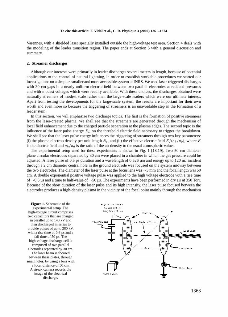
is the electric field andnh/n0 is the ratio of the air density to the usual atmospheric values.The experimental setup used for these experiments is shown in Fig. 1 [18,19]. Two 50 cm diameter
plane circular electrodes separated by 30 cm were placed in a chamber in which the gas pressure could beadjusted. A laser pulse of 0.5 ps duration and a wavelength of 0.526 µm and energy up to 120 mJ incidentthrough a 2 cm diameter central hole in the ground electrode was focused on the system midway betweenthe two electrodes. The diameter of the laser pulse at the focus lens was∼3 mm and the focal length was 50cm. A double exponential positive voltage pulse was applied to the high voltage electrode with a rise timeof ∼0.6 µs and a time to half-value of∼50 µs. The experiments have been performed in dry air at 350 Torr.Because of the short duration of the laser pulse and its high intensity, the laser pulse focused between theelectrodes produces a high-density plasma in the vicinity of the focal point mainly through the mechanism
Figure 1. Schematic of theexperimental setup. The
high-voltage circuit comprisestwo capacitors that are charged
in parallel up to 140 kV andthen discharged in series to
provide pulses of up to 280 kV,with a rise time of 0.6 µs and a
fall time of 50 µs. Thehigh-voltage discharge cell is
composed of two parallelelectrodes separated by 30 cm.
The laser beam is focusedbetween these plates, through
small holes, by using a lens witha focal distance of 50 cm.
A streak camera records theimage of the electrical
discharge.
1363
F. Vidal et al. / C. R. Physique 3 (2002) 1361–1374
of laser-induced photo-ionization of the ambient gas [20]. The plasma itself is heated mainly through themechanism of dissociative electron-ion recombination in which a significant part of the laser energy initiallyspent in ionization is converted into kinetic energy of the fragments of the dissociated molecules. Thisenergy will lead to significant expansion of the plasma typically∼1 ns after the laser pulse has passed.
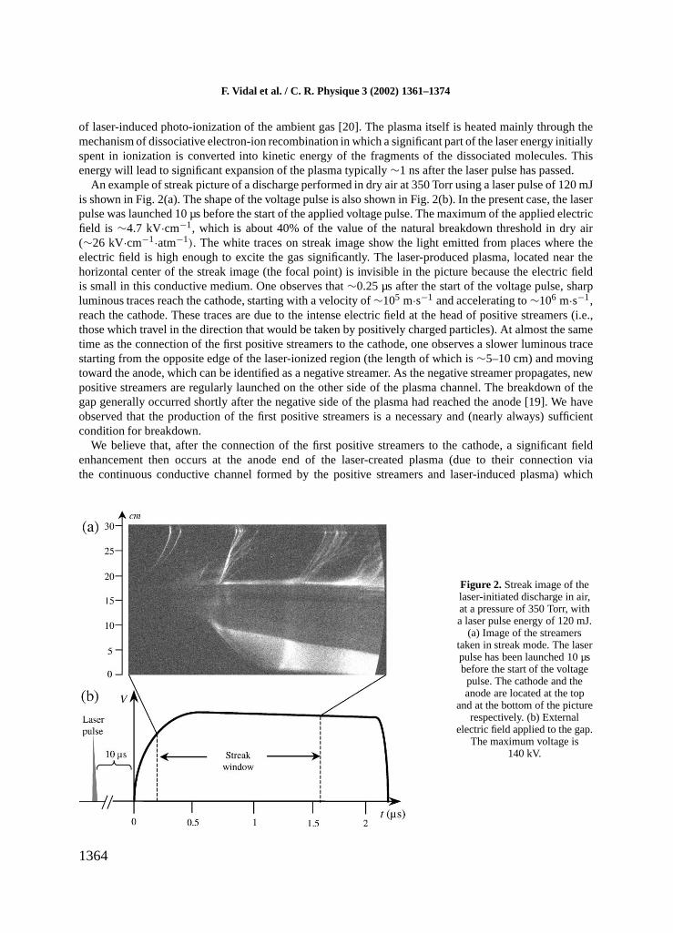
An example of streak picture of a discharge performed in dry air at 350 Torr using a laser pulse of 120 mJis shown in Fig. 2(a). The shape of the voltage pulse is also shown in Fig. 2(b). In the present case, the laserpulse was launched 10 µs before the start of the applied voltage pulse. The maximum of the applied electricfield is ∼4.7 kV·cm−1, which is about 40% of the value of the natural breakdown threshold in dry air(∼26 kV·cm−1·atm−1). The white traces on streak image show the light emitted from places where theelectric field is high enough to excite the gas significantly. The laser-produced plasma, located near thehorizontal center of the streak image (the focal point) is invisible in the picture because the electric fieldis small in this conductive medium. One observes that∼0.25 µs after the start of the voltage pulse, sharpluminous traces reach the cathode, starting with a velocity of∼105 m·s−1 and accelerating to∼106 m·s−1,reach the cathode. These traces are due to the intense electric field at the head of positive streamers (i.e.,those which travel in the direction that would be taken by positively charged particles). At almost the sametime as the connection of the first positive streamers to the cathode, one observes a slower luminous tracestarting from the opposite edge of the laser-ionized region (the length of which is∼5–10 cm) and movingtoward the anode, which can be identified as a negative streamer. As the negative streamer propagates, newpositive streamers are regularly launched on the other side of the plasma channel. The breakdown of thegap generally occurred shortly after the negative side of the plasma had reached the anode [19]. We haveobserved that the production of the first positive streamers is a necessary and (nearly always) sufficientcondition for breakdown.
We believe that, after the connection of the first positive streamers to the cathode, a significant fieldenhancement then occurs at the anode end of the laser-created plasma (due to their connection viathe continuous conductive channel formed by the positive streamers and laser-induced plasma) which
Figure 2. Streak image of thelaser-initiated discharge in air,at a pressure of 350 Torr, witha laser pulse energy of 120 mJ.
(a) Image of the streamerstaken in streak mode. The laserpulse has been launched 10 µsbefore the start of the voltagepulse. The cathode and theanode are located at the top
and at the bottom of the picturerespectively. (b) External
electric field applied to the gap.The maximum voltage is
140 kV.
1364
Pour citer cet article : F. Vidal et al., C. R. Physique 3 (2002) 1361–1374
causes the triggering of the negative streamers. The fact that this field enhancement mechanism wasnecessary to launch the negative streamers is due partly to the higher threshold required by negativestreamers [16] and, as discussed below, partly to the smaller electron density gradient on the anodeside.
In order to understand how the streamers are generated from the laser-created plasma, we have developeda numerical model describing the evolution of the plasma subjected to a time-dependent external electricfield [18]. The equation of continuity for the electrons, positive ions and negative ions have been solvedalong the axis of the plane electrodes for a given plasma width by taking into account electric fieldionization, electron–ion recombination, electron attachment with oxygen, and ion–ion recombination. Theinitial plasma conditions have been obtained using a simple geometrical propagation model for the laserpulse and by using the theoretical rate of photo-ionization [20].
The mechanism of streamer formation resulting from the model is as follows. Due to the fast electron–ion recombination, the initial plasma electron density can be represented roughly as a trapezium with aflat central part and two different inclined edges. On the influence of the external electric field, the plasmaparticles with opposite charges move in opposite directions, leaving a local net charge, which creates a localelectric field. Since no net charge is left in the flat part of the plasma profile, the local field essentially liesat the plasma edges and is even more significant when the electron density gradients at the edges are higher.When the appropriate conditions are met (amplitude of the external electric field, electron density, densitygradient, width of the edges, etc.), electron avalanches take place at the plasma edges, leading to the onsetof a streamer propagating along the axis toward the nearest electrode. It must be emphasized that the plasmacase is nothing like that of a floating metallic electrode where, because of its high conductivity, the skindepth is small compared with the width, and thus the external electric field is excluded. Because the metalconductivity is so high its value becomes irrelevant and we are left with a geometric field concentrationeffect due to the shape and placement of the conductor. In the laser-induced plasma case, the electrondensity is sufficiently low that the skin depth is large and the external electric field penetrates easily. Thussignificant modification of the externally imposed electric field here only occurs at the ends of the plasma,where there are high local electric fields due to charge separation. Unlike the conductor case, the effect isdirectly proportional to the electron density per unit length.
The experiments have shown that the minimum electric field required to trigger the breakdown can besignificantly reduced by increasing the laser pulse energy [19]. For example, in the experiments performedin air at 350 Torr, when the laser pulse is launched nearly in coincidence with the maximum voltage,threshold electric fields of∼5.6 kV·cm−1, ∼4.6 kV·cm−1 and ∼3.2 kV·cm−1 (the natural breakdownvalue being∼12 kV·cm−1) have been obtained for laser pulse energies of 15 mJ, 35 mJ and 120 mJrespectively.
From the theoretical investigations it has been concluded that the influence of the laser energy on thetriggering of streamers can be usefully described by means of two main parameters [21]:
(i) The first parameter is the electron density per unit lengthNe = neπR2p (wherene is the average
electron density per unit volume andRp is the plasma radius) of the plasma near the focal point. In [21] ithas been shown thatNe increases with the laser pulse energy. Besides, using the above mentioned numericalmodel for the onset of streamers [18], we have shown that the local electric fields induced by chargeseparation at the plasma edges increase significantly with bothRp andne, [19] and thus with the laserpulse energy. As discussed above, high local electric fields at the plasma edges can induce streamers, whichis a necessary condition for breakdown.
(ii) The second parameter is the effective electric fieldEeff = E/nh (nh being the air density). As thelaser pulse energy increases, more energy per unit volume is deposited in the plasma, causing its thermalexpansion and thus the increase of the effective electric fieldEeff. As is well-known, most electric field-dependent reactions in the plasma depend onEeff instead ofE alone [16]. Therefore, the decrease of theair densitynh due to thermal expansion (from conversion of ionization energy to plasma thermal energyand thus pressure) can enhance sufficiently the effect of the applied electric field to actually ionize the
1365
F. Vidal et al. / C. R. Physique 3 (2002) 1361–1374
plasma and thus to increase the electron density per unit lengthNe. (The induced expansion also probablyenhances the effect of the local electric field at the plasma edges.) There is, however, a characteristic coolingtime τth of the plasma-heated and expanded region, given byτth ∼ R2
p/4κh, whereκh is the air thermalconductance. After this time the plasma contracts back to its initial volume as its temperature drops bythermal conduction towards the temperature of the ambient medium. As shown in [21], this time scalecharacterizes the maximum delay between the laser pulse and the voltage pulse for which streamers can betriggered below the natural breakdown threshold.
3. Leader discharges
Since our main interest is the control of natural lightning by lasers, we have devoted the greater partof our efforts to understand the leader triggering and guiding properties of long laser plasma channels inlong air gaps (3–7 m) where stable and free propagation of leaders can take place. Our approach was tocharacterize experimentally the evolution of discharges, with and without a laser plasma, and to apply tothese the model of the positive discharge in long air gaps as elaborated by Bondiou and Gallimberti [22].We have studied two rod-plane configurations. In one (classical), a positive high voltage pulse is applied tothe rod electrode placed above the ground plane [23,24]. In the other (non-classical) configuration, the rodis placed on the ground plane and a negative high voltage pulse is applied to a large plane above [25].
In this section we will present results of the 7 m gap in the classical rod-plane configuration and showthat we can describe adequately the leader discharge in presence of a laser plasma channel by using theBondiou–Gallimberti model. We have observed experimentally that the linear chargeqL of a positive leaderis significantly smaller, compared to its ordinary value, when it develops along a laser-created plasmachannel. In the model,qL is a parameter which determines the rate of leader growth, linking its velocityvL
with the current inputIL produced by the progression of the corona front through the relationvL = IL/qL.We have observed that the effect of a laser-produced plasma on the discharge can be accounted for in theBondiou–Gallimberti model by simply reducing the value ofqL over the laser plasma channel length.
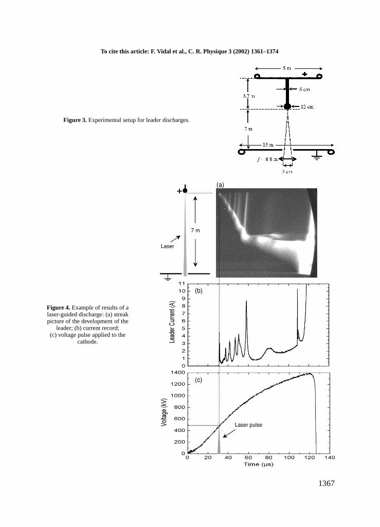
The experiments have been performed at the Hydro-Québec High-Voltage Laboratory. In our exper-imental classical setup, shown in Fig. 3, a circular 15-meter diameter ground plane electrode, with acentral hole for laser beam propagation, is located 3 m above the floor. The top electrode is a 3.7 mrod (diameter 6 cm) with a 12 cm diameter sphere at its tip, attached at the center of a 5 m diameterelectrode. (This top electrode is far enough from the gap to have a negligible influence on the electricfield distribution.) A high voltage (HV) generator was used to apply a positive voltage pulse to the rodelectrode, with a critical rise time of 270 µs matched to the gap length. The time to half-value of theapplied voltage pulse was 2.5 ms. Because of the necessity of leaving the high-field region completelyclear and to avoid the interference to the laser system from the high-voltage power system operation, thelaser system was placed in a shielded room outside the high voltage test, some 30 meters distant. Weused a BMI-Thomson Ti: sapphire laser system (λ = 800 nm, minimum pulse duration= 60 fs, maxi-mum energy in the laser pulse after compression= 500 mJ). An image-relay system enclosed in near-vacuum (10−5 Torr) transferred the beam from the laser room to the test site (below the ground elec-trode). The beam had an elliptical shape with principal axes of 4.5 cm and 3.2 cm. We used lensesof various focal lengths (4.7 m to 8.8 m) to focus the laser beam approximately 30–40 cm below thesphere at the tip of the top electrode. The minimum pulse duration (measured by second order auto-correlation) that was used in these experiments was around 0.6–1 ps corresponding, with our opticalarrangement, to the appearance of white light on the surface of the focussing lens (threshold of damageon this lens).
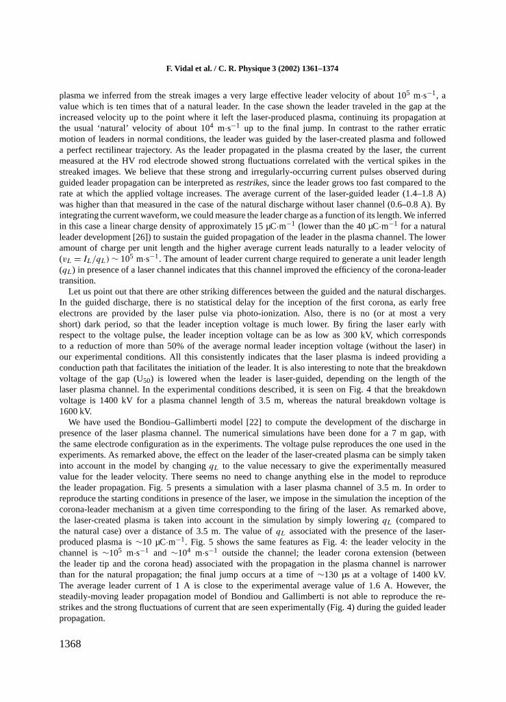
An example illustrating the dynamics of a laser-induced discharge appears in Fig. 4. We present a streakrecord, the leader current and the corresponding HV pulse. For this event, the plasma was produced witha 200-mJ laser pulse and the plasma channel length was∼3.5 m. The laser beam was launched about30 µs after the start of the voltage pulse, which had a peak amplitude of 1600 kV. With the laser-produced
1366
To cite this article: F. Vidal et al., C. R. Physique 3 (2002) 1361–1374
Figure 3. Experimental setup for leader discharges.
Figure 4. Example of results of alaser-guided discharge: (a) streakpicture of the development of the
leader; (b) current record;(c) voltage pulse applied to the
cathode.
1367
F. Vidal et al. / C. R. Physique 3 (2002) 1361–1374
plasma we inferred from the streak images a very large effective leader velocity of about 105 m·s−1, avalue which is ten times that of a natural leader. In the case shown the leader traveled in the gap at theincreased velocity up to the point where it left the laser-produced plasma, continuing its propagation atthe usual ‘natural’ velocity of about 104 m·s−1 up to the final jump. In contrast to the rather erraticmotion of leaders in normal conditions, the leader was guided by the laser-created plasma and followeda perfect rectilinear trajectory. As the leader propagated in the plasma created by the laser, the currentmeasured at the HV rod electrode showed strong fluctuations correlated with the vertical spikes in thestreaked images. We believe that these strong and irregularly-occurring current pulses observed duringguided leader propagation can be interpreted asrestrikes, since the leader grows too fast compared to therate at which the applied voltage increases. The average current of the laser-guided leader (1.4–1.8 A)was higher than that measured in the case of the natural discharge without laser channel (0.6–0.8 A). Byintegrating the current waveform, we could measure the leader charge as a function of its length. We inferredin this case a linear charge density of approximately 15 µC·m−1 (lower than the 40 µC·m−1 for a naturalleader development [26]) to sustain the guided propagation of the leader in the plasma channel. The loweramount of charge per unit length and the higher average current leads naturally to a leader velocity of(vL = IL/qL) ∼ 105 m·s−1. The amount of leader current charge required to generate a unit leader length(qL) in presence of a laser channel indicates that this channel improved the efficiency of the corona-leadertransition.
Let us point out that there are other striking differences between the guided and the natural discharges.In the guided discharge, there is no statistical delay for the inception of the first corona, as early freeelectrons are provided by the laser pulse via photo-ionization. Also, there is no (or at most a veryshort) dark period, so that the leader inception voltage is much lower. By firing the laser early withrespect to the voltage pulse, the leader inception voltage can be as low as 300 kV, which correspondsto a reduction of more than 50% of the average normal leader inception voltage (without the laser) inour experimental conditions. All this consistently indicates that the laser plasma is indeed providing aconduction path that facilitates the initiation of the leader. It is also interesting to note that the breakdownvoltage of the gap (U50) is lowered when the leader is laser-guided, depending on the length of thelaser plasma channel. In the experimental conditions described, it is seen on Fig. 4 that the breakdownvoltage is 1400 kV for a plasma channel length of 3.5 m, whereas the natural breakdown voltage is1600 kV.
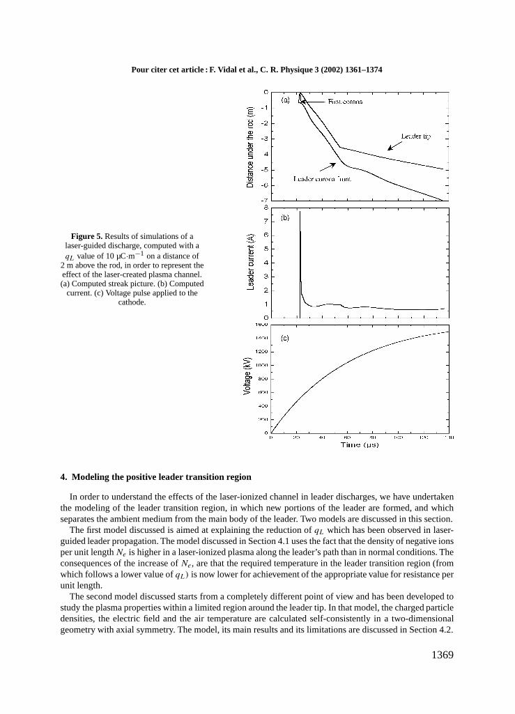
We have used the Bondiou–Gallimberti model [22] to compute the development of the discharge inpresence of the laser plasma channel. The numerical simulations have been done for a 7 m gap, withthe same electrode configuration as in the experiments. The voltage pulse reproduces the one used in theexperiments. As remarked above, the effect on the leader of the laser-created plasma can be simply takeninto account in the model by changingqL to the value necessary to give the experimentally measuredvalue for the leader velocity. There seems no need to change anything else in the model to reproducethe leader propagation. Fig. 5 presents a simulation with a laser plasma channel of 3.5 m. In order toreproduce the starting conditions in presence of the laser, we impose in the simulation the inception of thecorona-leader mechanism at a given time corresponding to the firing of the laser. As remarked above,the laser-created plasma is taken into account in the simulation by simply loweringqL (compared tothe natural case) over a distance of 3.5 m. The value ofqL associated with the presence of the laser-produced plasma is∼10 µC·m−1. Fig. 5 shows the same features as Fig. 4: the leader velocity in thechannel is∼105 m·s−1 and ∼104 m·s−1 outside the channel; the leader corona extension (betweenthe leader tip and the corona head) associated with the propagation in the plasma channel is narrowerthan for the natural propagation; the final jump occurs at a time of∼130 µs at a voltage of 1400 kV.The average leader current of 1 A is close to the experimental average value of 1.6 A. However, thesteadily-moving leader propagation model of Bondiou and Gallimberti is not able to reproduce the re-strikes and the strong fluctuations of current that are seen experimentally (Fig. 4) during the guided leaderpropagation.
1368
Pour citer cet article : F. Vidal et al., C. R. Physique 3 (2002) 1361–1374
Figure 5. Results of simulations of alaser-guided discharge, computed with aqL value of 10 µC·m−1 on a distance of
2 m above the rod, in order to represent theeffect of the laser-created plasma channel.(a) Computed streak picture. (b) Computed
current. (c) Voltage pulse applied to thecathode.
4. Modeling the positive leader transition region
In order to understand the effects of the laser-ionized channel in leader discharges, we have undertakenthe modeling of the leader transition region, in which new portions of the leader are formed, and whichseparates the ambient medium from the main body of the leader. Two models are discussed in this section.
The first model discussed is aimed at explaining the reduction ofqL which has been observed in laser-guided leader propagation. The model discussed in Section 4.1 uses the fact that the density of negative ionsper unit lengthNe is higher in a laser-ionized plasma along the leader’s path than in normal conditions. Theconsequences of the increase ofNe, are that the required temperature in the leader transition region (fromwhich follows a lower value ofqL) is now lower for achievement of the appropriate value for resistance perunit length.
The second model discussed starts from a completely different point of view and has been developed tostudy the plasma properties within a limited region around the leader tip. In that model, the charged particledensities, the electric field and the air temperature are calculated self-consistently in a two-dimensionalgeometry with axial symmetry. The model, its main results and its limitations are discussed in Section 4.2.
1369
F. Vidal et al. / C. R. Physique 3 (2002) 1361–1374
4.1. Explaining the lowering of qL
The mechanism described here to explain the lowering ofqL follows the guideline of the model proposedby Gallimberti [26] (a component of the Bondiou–Gallimberti model [22]) for leaders propagating innormal conditions (without laser-ionized channel). According to that model, the appropriate conductivity inthe transition region is achieved by detaching the electrons from the negative ions of the leader’s path. (Dueto the high electron mobility, the detached electrons increase considerably the conductivity.) The negativeions in the streamer filaments (the part in contact with the leader region) result from the rapid attachment(in only ∼10−8 s) of the electrons initially generated in the streamer heads. The same applies to the plasmagenerated some time earlier by the short-pulse laser. In the leader transition region, the electron detachmentnecessary to advance the leader is presumed to be achieved by heating the air to a temperature of∼1500 Kthrough collisions of the neutral air particles with the charged particles accelerated by the electric field atthe leader tip.
The starting point of the model presented here is that the density of negative ions per unit length alongthe leader’s path is higher for a laser-ionized channel than for an ensemble of streamer filaments. Thisassertion is justified as follows. The laser ionized channel is characterized, in our experimental conditions,by an average diameter of∼1 mm and a negative ion density of 1012–1013 cm−3 [25]. In virgin air anew portion of the leader grows in an ionized channel made of a few streamer filaments. These filamentsare characterized by a diameter of 50–100 µm and a negative ion density of 1012–1013 cm−3 [16]. Oneconcludes that the ratio
f = (N−)laser channel/(N−)streamer channel, (1)
where(N−)laser channeland(N−)streamer channelare the density per unit length of negative ions in the laser-ionized channel and in a streamer-ionized channel respectively, is of the order of the ratio between thecross-sectional areas of the laser-ionized plasma and the streamer-ionized region, i.e., of the order of 10–100.
In order to extend Gallimberti’s model to the case of a laser-ionized channel, we first assume that theleader geometry itself and the electric field distribution inside the leader are practically unaffected by thelaser-ionized channel. Following this assumption, and neglecting the influence of the leader velocity, thecharge per unit length reads simply [26,22]
qL ≈ 3.5× 10⁻⁸(Tc − T0). (2)
The mechanism by whichqL is lowered might well be achieved as follows. In a medium in which a higherdensity of negative ions per unit length is available, such as in a laser-ionized channel, only a smallertemperatureTc in the transition region has to be achieved. This is because the negative ions themselvescontribute significantly to the conductivity so that a smaller fraction of the electrons have to be detached toobtain the appropriate lowresistance per unit length R. The latter is defined as the reciprocal of the laterallyintegrated conductivity, and is expressed as
R−1 = eµeNe + eµiN− + eµiN+. (3)
Hereµe andµi are the mobility of electrons and ions respectively, andNe, N− andN+ are the densitiesper unit length of electrons, negative ions and positive ions respectively. Since the temperatureT0 of the airalong the path of the leader depends weakly on the presence of a laser-ionized channel [24], the loweringof qL thus follows directly from the lowering of the temperatureTc in the transition region.
Quantitative results have been obtained as follows. By assuming that: (i) detachment nearly balancesattachment in the transition region (as in Gallimberti’s model), and (ii) that the plasma is neutral, one caneasily expressR as a function ofN− along the leader’s path. The temperatureTc as a function off , Eq. (1),can then be obtained from the conditionR(T = 1500 K) = R(Tc).
1370
To cite this article: F. Vidal et al., C. R. Physique 3 (2002) 1361–1374
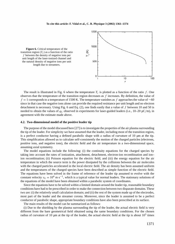
Figure 6. Critical temperature of thetransition region (Tc) as a function of the ratio
f between the density of negative ions perunit length of the laser-ionized channel andthe natural density of negative ions per unit
length due to streamers.
The result is illustrated in Fig. 6 where the temperatureTc is plotted as a function of the ratiof . Oneobserves that the temperature of the transition region decreases asf increases. By definition, the value off = 1 corresponds to a temperature of 1500 K. The temperature vanishes asf approaches the value of∼60since in that case the negative ions alone can provide the required resistance per unit length and no electrondetachment is necessary. Using Fig. 6 and Eq. (2), one finds easily that a value off between 10 and 50 isneeded to obtain the values ofqL observed in experiments for laser-guided leaders (i.e., 10–20 µC/m), inagreement with the estimate made above.
4.2. Two-dimensional model of the positive leader tip
The purpose of the model discussed here [27] is to investigate the properties of the air plasma surroundingthe tip of the leader. For simplicity we have assumed that the leader, including most of the transition region,is a perfect conductor having a defined parabolic shape with a radius of curvature of 10 µm at the tip.This simplification allowed us to calculate self-consistently the motion of the charged particles (electrons,positive ions, and negative ions), the electric field and the air temperature in a two-dimensional space,assuming axial symmetry.
The model equations include the following: (i) the continuity equations for the charged species bytaking into account the rates of ionization, attachment, detachment, electron-ion recombination and ion–ion recombination; (ii) Poisson equation for the electric field; and (iii) the energy equation for the airtemperature in which the source term is the power dissipated by the collisions between the air moleculeswith the charged particles accelerated in the local electric field. The air density has been assumed uniformand the temperatures of the charged species have been described as simple function of the electric field.The equations have been solved in the frame of reference of the leader tip assumed to evolve with theconstant velocityvL = 104 m·s−1, which is a typical value for normal leaders. The stationary solutions ofthe equations of the model have been obtained within a parabolic system of coordinates.
Since the equations have to be solved within a limited domain around the leader tip, reasonable boundaryconditions have had to be prescribed in order to make the connection between two disparate domains. Thesetwo are: (i) the relatively small calculation domain; and (ii) the rest of the system made up of the electrodes,most part of the leader and the streamer corona. Moreover, since the leader is assumed to be a perfectconductor of parabolic shape, appropriate boundary conditions have also been prescribed at its surface.
The main results of the model can be summarized as follows:(i) Due to the shielding by the plasma surrounding the tip of the leader, the actual electric field is very
different from the bare geometrical field obtained using the same boundary conditions. For the chosenradius of curvature of 10 µm at the tip of the leader, the actual electric field at the tip is about 103 times
1371
F. Vidal et al. / C. R. Physique 3 (2002) 1361–1374
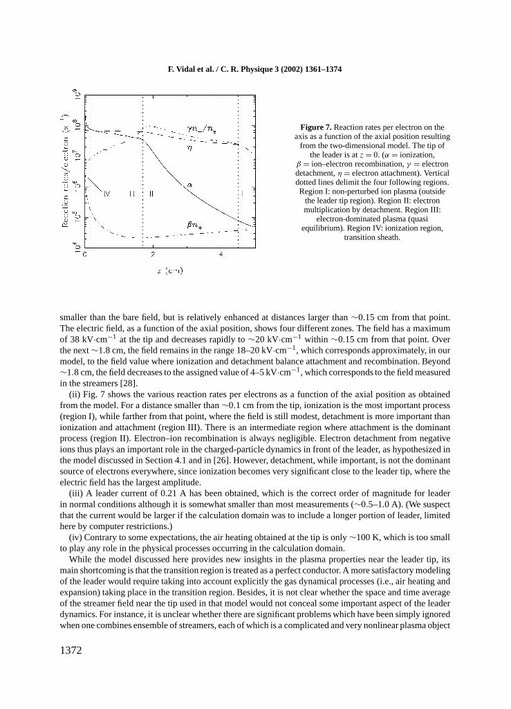
Figure 7. Reaction rates per electron on theaxis as a function of the axial position resulting
from the two-dimensional model. The tip ofthe leader is atz = 0. (α = ionization,
β = ion–electron recombination,γ = electrondetachment,η = electron attachment). Verticaldotted lines delimit the four following regions.Region I: non-perturbed ion plasma (outside
the leader tip region). Region II: electronmultiplication by detachment. Region III:
electron-dominated plasma (quasiequilibrium). Region IV: ionization region,
transition sheath.
smaller than the bare field, but is relatively enhanced at distances larger than∼0.15 cm from that point.The electric field, as a function of the axial position, shows four different zones. The field has a maximumof 38 kV·cm−1 at the tip and decreases rapidly to∼20 kV·cm−1 within ∼0.15 cm from that point. Overthe next∼1.8 cm, the field remains in the range 18–20 kV·cm−1, which corresponds approximately, in ourmodel, to the field value where ionization and detachment balance attachment and recombination. Beyond∼1.8 cm, the field decreases to the assigned value of 4–5 kV·cm−1, which corresponds to the field measuredin the streamers [28].
(ii) Fig. 7 shows the various reaction rates per electrons as a function of the axial position as obtainedfrom the model. For a distance smaller than∼0.1 cm from the tip, ionization is the most important process(region I), while farther from that point, where the field is still modest, detachment is more important thanionization and attachment (region III). There is an intermediate region where attachment is the dominantprocess (region II). Electron–ion recombination is always negligible. Electron detachment from negativeions thus plays an important role in the charged-particle dynamics in front of the leader, as hypothesized inthe model discussed in Section 4.1 and in [26]. However, detachment, while important, is not the dominantsource of electrons everywhere, since ionization becomes very significant close to the leader tip, where theelectric field has the largest amplitude.
(iii) A leader current of 0.21 A has been obtained, which is the correct order of magnitude for leaderin normal conditions although it is somewhat smaller than most measurements (∼0.5–1.0 A). (We suspectthat the current would be larger if the calculation domain was to include a longer portion of leader, limitedhere by computer restrictions.)
(iv) Contrary to some expectations, the air heating obtained at the tip is only∼100 K, which is too smallto play any role in the physical processes occurring in the calculation domain.
While the model discussed here provides new insights in the plasma properties near the leader tip, itsmain shortcoming is that the transition region is treated as a perfect conductor. A more satisfactory modelingof the leader would require taking into account explicitly the gas dynamical processes (i.e., air heating andexpansion) taking place in the transition region. Besides, it is not clear whether the space and time averageof the streamer field near the tip used in that model would not conceal some important aspect of the leaderdynamics. For instance, it is unclear whether there are significant problems which have been simply ignoredwhen one combines ensemble of streamers, each of which is a complicated and very nonlinear plasma object
1372
Pour citer cet article : F. Vidal et al., C. R. Physique 3 (2002) 1361–1374
into an effective mean-plasma model. However, such an improved model would involve difficult conceptualand computational issues that we have chosen to avoid at this stage of our investigations.
A consequence of the ‘perfect conductor’ assumption made here is likely that the electric field andionization at the tip are overestimated (despite the observed damping due to space charges) since otherwisethe potential would vary more gradually. This lowering of ionization at the tip would be more consistentwith the electron detachment models discussed in [26] and in Section 4.1. As a matter of fact, it shouldbe realized that ionization is actually difficult to reconcile with leader transition region models in whichdetachment plays a central role. This is because ionization alone, if significant enough, could well feedthe leader transition region with enough free electrons to achieve the required conductivity. The electrondetachment process could then be comparatively negligible.
Finally, let us add that the very low air heating found at the tip in this model probably indicates that theleader heating does not take place suddenly at the tip. The heating is more likely to be distributed moregradually in the transition region (possibly over centimeters), in a way more consistent with the simplemodel discussed in Section 4.1.
5. Summary and conclusions
This paper has presented experimental and modeling results concerning discharges triggered by focusedultrashort laser pulses. Streamer discharges in 30 cm gaps and leader discharges in gaps up to 7 m havebeen considered. Our theoretical investigations on the leader transition region have also been discussed inSection 4.
Laser pulses modify the medium in which the discharge takes place through ionization and gas heating.We have observed that in 30 cm plane–plane air gaps at modest pressure (350 Torr) where streamerformation dominates, laser energies of 120 mJ could trigger discharges at only∼25% of the naturalbreakdown electric field. Streamers are triggered from the edges of the laser-created plasma through themechanism of local field enhancement due to charge separation. Important plasma parameters are theelectron density per unit lengthNe and the effective electric fieldEeff. The typical time by which theheated plasma keeps its ability to trigger streamers below the natural breakdown electric field is given bythe thermal conduction characteristic timeτth.
In air gaps of several meters, a single laser pulse has been shown to trigger and guide the leader discharge,and to increase the leader velocity by a factor of∼ 10. Modeling using the Bondiou–Gallimberti model hasbeen shown to provide results in good agreement with the experiments provided the parameterqL (thecharge per unit length) is lowered consistently with the experimental observations. In such large gaps, theheating of the ambient gas by the laser pulse seems to be negligible. The main effect of the laser pulse islikely to increase the density of negative ions per unit length in which the leader propagates. A model of theleader transition region based on this finding and intended to explain the lowering ofqL has been discussedin Section 4.1.
The two-dimensional model of the plasma near the leader tip discussed in Section 4.2 demonstrates thatmuch remains to be learned concerning the mechanisms of propagation of the leader from the point ofview of the elementary processes. The assumption made in that model, that most of the transition regionis a perfect conductor, because of the high ionization rate obtained at the leader tip, does not seem to beconsistent with a simple picture dominated by negative ion density per unit length. It rather seems thatan extended transition region in which the conductivity would increase gradually would constitute a morerealistic picture of the leader transition region. The self-consistent modeling of the leader transition regionstill presents major challenges, both conceptual and technical, to the researchers in the field of lightningdischarges.
The feasibility study that we have undertaken is encouraging regarding the understanding of the controlof lightning by means of lasers. The achievement of this goal could be possible in the near future in viewof the rapid development of compact short pulse laser systems.
1373
F. Vidal et al. / C. R. Physique 3 (2002) 1361–1374
Acknowledgments. The authors are grateful to Dr. Anne Bondiou-Clergerie and Dr. Philippe Lalande fromONERA, and Dr. Ivo Gallimberti from the University of Padova, for making possible the use of the codes of theBondiou–Gallimberti model, for helping in the interpretation of the modeling results and for many helpful discussions.
References
[1] W.K. Pendleton, A.H. Guenther, Rev. Sci. Instrum. 36 (1965) 1546.[2] A.H. Guenther, J.R. Bettis, IEEE J. Quant. Electron. QE-3 (1967) 581.[3] A.G. Akmanov, L.W. Rivlin, V.S. Shildyaev, JETP Lett. 8 (1968) 258.[4] R.C. Klewe, M.B.C. Quigley, B.A. Tozer, Appl. Phys. Lett. 15 (1969) 155.[5] V.I. Vladimirov, G.M. Malyshev, G.T. Razdobarin, V. Semenov, Soviet Phys. Tech. Phys. 14 (1969) 677.[6] D.W. Koopman, T.D. Wilkerson, J. Appl. Phys. 42 (1971) 1883.[7] L.M. Ball, Appl. Opt. 13 (1974) 2292.[8] D. Wang, T. Ushio, Z.I. Kawazaki, K. Matsuura, Y. Shimada, S. Uchida, C. Yamanaka, Y. Izawa, Y. Sonoi, N. Si-
mokura, J. Atmos. Terr. Phys. 57 (1995) 459.[9] M. Miki, T. Shindo, Y. Aihara, J. Phys. D 29 (1996) 1984.
[10] T. Yamanaka, S. Uchida, Y. Shimada, H. Yasuda, S. Motokoshi, K. Tsubakimoto, Z. Kawasaki, Y. Ishikubo,M. Adachi, C. Yamanaka, Proc. SPIE 3343 (1998) 281.
[11] K. Nakamura, T. Suzuki, C. Yamabe, K. Horii, Elec. Engrg. Japan 114 (1994) 69.[12] M. Miki, A. Wada, J. Appl. Phys. 80 (1996) 3208.[13] A. Braun, G. Korn, X. Liu, D. Du, J. Squier, G. Mourou, Opt. Lett. 20 (1995) 73.[14] B. La Fontaine, F. Vidal, Z. Jiang, C.Y. Chien, D. Comtois, A. Desparois, T.W. Johnston, J.-C. Kieffer, H. Pépin,
Phys. Plasmas 6 (1999) 1615.[15] X.M. Zhao, J.C. Diels, C.Y. Wang, J.M. Elizondo, IEEE J. Quantum Electron. 31 (1995) 599.[16] Yu.P. Raizer, Gas Discharges, Springer-Verlag, Berlin, 1991.[17] F.A.M. Rizk, IEEE Power Delivery 4 (1989) 596.[18] B. La Fontaine, F. Vidal, D. Comtois, C.Y. Chien, A. Desparois, T.W. Johnston, J.C. Kieffer, H.P. Mercure, H. Pé-
pin, F.A.M. Rizk, IEEE Trans. Plasma Sci. 27 (1999) 688.[19] A. Desparois, B. La Fontaine, A. Bondiou-Clergerie, C.Y. Chien, D. Comtois, T.W. Johnston, J.-C. Kieffer,
H.P. Mercure, H. Pépin, F.A.M. Rizk, F. Vidal, IEEE Trans. Plasma. Sci. 28 (2000) 1755.[20] L.V. Keldysh, J. Exp. Theor. Phys. 47 (1964) 1945.[21] F. Vidal, D. Comtois, C.Y. Chien, A. Desparois, B. La Fontaine, T.W. Johnston, J.-C. Kieffer, H.P. Mercure, H. Pé-
pin, F.A. Rizk, IEEE Trans. Plasma Sci. 28 (2000) 418.[22] A. Bondiou, I. Gallimberti, J. Phys. D 27 (1994) 1252.[23] D. Comtois, C.Y. Chien, A. Desparois, F. Génin, G. Jarry, T.W. Johnston, J.-C. Kieffer, B. La Fontaine, F. Martin,
R. Mawassi, H. Pépin, F.A.M. Rizk, F. Vidal, P. Couture, H.P. Mercure, C. Potvin, A. Bondiou-Clergerie,I. Galllimberti, Appl. Phys. Lett. 76 (2000) 819.
[24] H. Pépin, D. Comtois, F. Vidal, C.Y. Chien, A. Desparois, T.W. Johnston, J.C. Kieffer, B. La Fontaine, F. Mar-tin, F.A.M. Rizk, C. Potvin, P. Couture, H.P. Mercure, A. Bondiou-Clergerie, P. Lalande, I. Gallimberti, Phys.Plasmas 8 (2001) 2532.
[25] D. Comtois, H. Pépin, F. Vidal, F.A.M. Rizk, C.Y. Chien, T.W. Johnston, J.C. Kieffer, B. La Fontaine, F. Martin,C. Potvin, P. Couture, H.P. Mercure, A. Bondiou-Clergerie, P. Lalande, I. Gallimberti, Part I (experiments) andPart II (modeling), IEEE Trans. Plasma Sci., submitted.
[26] I. Gallimberti, J. Phys. 40 (1979) 193.[27] F. Vidal, I. Gallimberti, F.A.M. Rizk, T.W. Johnston, A. Bondiou-Clergerie, D. Comtois, J.C. Kieffer, B. La
Fontaine, H.P. Mercure, to be published in IEEE Trans. Plasma Sci., June 2002 issue.[28] B. Hutzler, D. Hutzler, EDF Bull. Direction Études Rech. Sér. B Réseaux Électriques, Matériels Électriques 4
(1982) 11.
1374