Embed Size (px)
Citation preview
Transverse nonlocal effects in optical reorientationof nematic liquid crystals
Etienne Brasselet
Laboratoire de Physique UMR 5672, École Normale Supérieure de Lyon, 46 Allée d’Italie,69364 Lyon Cedex 07, France
Aurélien Lherbier and Louis J. Dubé*
Départment de Physique, de Génie Physique, et d’Optique, Université Laval, Cité Universitaire,Québec, Canada G1K 7P4
Received April 4, 2005; revised June 28, 2005; accepted July 20, 2005
We reexamine the optical reorientation of a homeotropic nematic-liquid-crystal film under finite beam-size ex-citation and linear polarization. We study the case of normal and oblique incidence (extraordinary wave). Un-der the most basic assumptions (geometrical optics approximation, elastic isotropy) we systematically analyzethe dependence of transverse nonlocal effects as a function of the angle of incidence, the beam size, and theintensity. Besides recovering some well-known results (Fréedericksz transition threshold and spatial extensionof the molecular reorientation as a function of the beam size), we identify a series of nonmonotonous behaviorsof the material response as well as shape variations of the reorientation profiles. © 2006 Optical Society ofAmerica
OCIS codes: 160.3710, 190.4420.
1. INTRODUCTIONShortly after the discovery of the optical Fréedericksztransition (OFT) in nematic liquid crystals (NLCs) byZolot’ko et al.1 in 1981, it was realized2–4 that the elastictorque arising from the finite beam size was responsiblefor an increase of the OFT threshold as the beam diam-eter was reduced. These earlier studies were mainly con-cerned with the case of a linearly polarized light beam im-pinging at normal and small oblique incidence onto ahomeotropic NLC film. Finite beam size has also beenshown to affect the typical times of reorientation and re-laxation in these systems5 (see also Ref. 6 for a more re-cent study). Another consequence of the finiteness of thebeam is the observation of diffraction ring patterns in thefar field resulting from self-phase modulation.7 The struc-ture of these patterns has been studied under various as-pects, namely the influences of the field curvature,8 theincident beam power,9 and the elastic anisotropy of thematerial.10,11 In a broader context, the (transverse) nonlo-cality associated with a finite beam dimension is a center-piece of present research activities in modulation insta-bilities and spatial solitons in liquid-crystal materials(e.g., Refs. 12 and 13).
In the pioneering work of Khoo et al.,14 transverse non-local (TNL) manifestations were studied through the de-pendence of the transverse reorientation profiles on the fi-nite beam size. The researchers confined their study tolinear polarization and arrived at the following conclu-sions: Under Gaussian excitation, the light-induced pro-files are in general non-Gaussian and their spatial exten-sion (i.e., width) strongly depends on the beam diameter.Under the same simplifying assumptions as those foundin Ref. 14 (geometrical optics approximation, elastic isot-
ropy), we devote this work to a systematic study of the de-pendence of the shape, width, and amplitude of the trans-verse profiles with respect to the angle of incidence ���,the beam size ��� and the light intensity ���. Besides theirfundamental interest, our results could serve as a neces-sary first step toward a quantitative description in situa-tions where the infinite-plane-wave (IPW) treatmentfails.
After a brief theoretical introduction and some detailsof the numerical implementation in Section 2, the reori-entation profiles are calculated from the Euler–Lagrangeequations in Section 3 (normal and oblique incidence). Inso doing, we confirm and extend previous studies at andabove the OFT threshold under a unified treatment forarbitrary angles of incidence. We also identify a series ofnonmonotonous behaviors of the NLC response (reorien-tation amplitude versus � at fixed �, reorientation widthversus � at fixed �) as well as shape variations of the re-orientation profiles. We complete the section with a quali-tative interpretation of the appearance of a characteristicbeam size ��c� below which TNL effects are important. Wealso discuss the role of transverse nonlocality in a dy-namical context. Finally, we summarize our findings inSection 4.
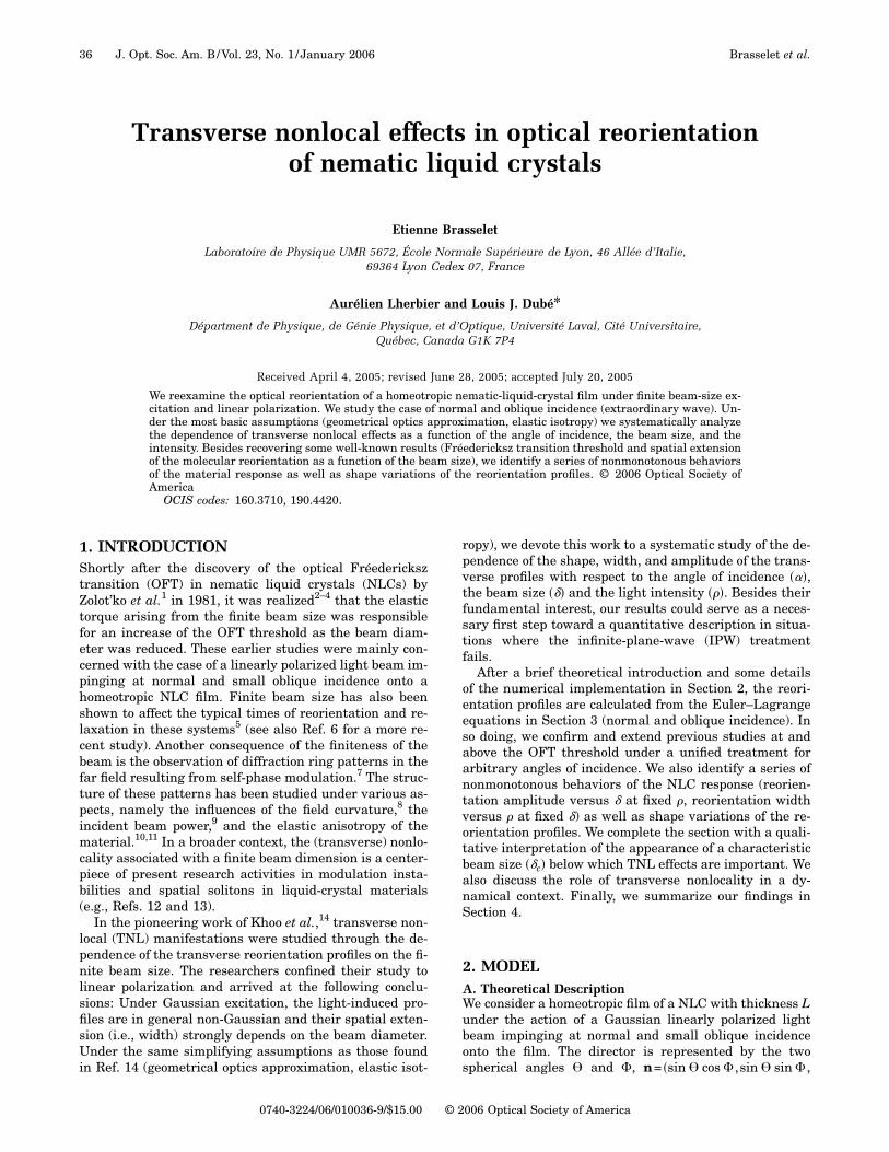
2. MODELA. Theoretical DescriptionWe consider a homeotropic film of a NLC with thickness Lunder the action of a Gaussian linearly polarized lightbeam impinging at normal and small oblique incidenceonto the film. The director is represented by the twospherical angles � and �, n= �sin � cos � ,sin � sin � ,
36 J. Opt. Soc. Am. B/Vol. 23, No. 1 /January 2006 Brasselet et al.
0740-3224/06/010036-9/$15.00 © 2006 Optical Society of America
cos �� [Fig. 1(a)], and its reorientation profile is obtainedfrom the minimization of the total free energy of the sys-tem. In the present study the electric field is extraordi-nary polarized, and for the one elastic constant approxi-mation, namely K1=K2=K3, both the complex electricfield E and the director n can be assumed to lie in the�x ,z� plane (i.e., �=0).15 In addition, we assume that thecylindrical symmetry is preserved, a valid approximationfor small angles of incidence. The intensity profile canthen be written as I�x� ,y���I�x ,y�, where �x� ,y�� is in theplane perpendicular to the wave vector k and �x ,y ,z� isthe laboratory fixed frame associated with the cell [Fig.1(b)]. The incident Gaussian intensity profile can there-fore be written as I�r�=I0G�r ,w0�, where G�r ,w�=exp�−2r2 /w2� is the Gaussian profile with radius w atexp�−2� of its maximum value with r2=x2+y2 and w0 isthe beam waist. The corresponding equation governingthe director reorientation is well known and is expressedas
�2�
�r2 +1
r
��
�r+
�2�
�z2 +�a
16�K�sin 2���Ex�2 − �Ez�2�
+ cos 2��ExEz* + Ex
*Ez�� = 0, �1�
where �a=��−�� is the dielectric susceptibility anisotropy(at optical frequency) with �� and �� being the susceptibil-ity parallel and perpendicular to the director. We shallfurther assume small transverse variations of the rel-evant functions on the scale of the wavelength � in orderto use the following forms for the electric field componentsEx and Ez, namely,
Ex = E�r����zz − sin2 �0�/���1/4 exp�i��0,r,z��, �2�
Ez = E�r����zz − sin2 �0�/���1/4 exp�i��0,r,z��
����1/2 sin �0/�zz����zz − sin2 �0�/���−1/2 − ��xz/�zz�.
�3�
These expressions were initially obtained in the limitingcase of the IPW approximation in Ref. 15. In these equa-tions E�r��I�r�1/2 is the transverse profile of the incidentelectric field amplitude, �ij=���ij+�aninj is the dielectricsusceptibility tensor, �ij is the Kronecker symbol, and��0 ,r ,z� is the propagation phase that will not play arole in Eq. (1). In a typical situation in which the cellthickness is L=100 �m and �=0.5 �m, the previous ap-proximation w0 � corresponds to a ratio �=2w0 /L be-tween the beam diameter and the cell thickness muchgreater than 10−2 (or equivalently 2w0 1 �m). This con-dition will be well satisfied in the following simulations.
The angle ��r ,z� will be further searched in the sim-plest form that respects the homeotropic boundary condi-tions ��r ,0�=��r ,L�=0, namely,
��r,z� = R�r�sin��z/L�. �4�
Then the differential equation that determines R�r� is ob-tained by multiplying Eq. (1) by sin��z /L� and integrat-ing from z=0 to L. By retaining terms up to R3 and �2,one finally obtains
�2R
�r2+
1
r
�R
�r− �2R + �G�r,w0�
i=0
3
ai���Ri = 0 �5�
with the boundary conditions
�R
�r�0� = 0, lim
r→�
R�r� = 0. �6�
In these equations, all lengths are normalized to the cellthickness (i.e., X�X /L) and
a0��� = 4��,
a1��� = �2�1 −3
2��2 ,
a2��� =8�
3�1 − 3���,
�3��� =�2
8 �5 − 9� +�45� − 33�
2��2� . �7�
We have introduced the material parameter �=�� /��, theinternal angle �=�0 /��
1/2, and the normalized intensity �=I0 /Ilin
� . The intensity Ilin� =�2cK�� / �L2�a��
1/2� is the OFTthreshold value �W m−2� for a linearly polarized excitationlight impinging on the film at normal incidence in thelimit of the IPW approximation.
It is worth to compare these results with those of Khooet al.14 obtained for the same interaction geometry. Theirresults are labeled with the index “K.” Those authorsstudied separately the normal ��=0� and oblique ���0�incidence cases. In the first case, they obtained
a0,K�0� = 0 = a0�0�,
a1,K�0� = �2 = a1�0�,
a2,K�0� = 0 = a2�0�,
a3,K�0� = −�2
2� a3�0�, �8�
and in the second case they found, rewriting the results inthe limit of small � and noting that the following expres-sion for a0,K��� takes into account the correction of the
Fig. 1. (a) Representation of the director n with the two angles� and �. (b) Interaction geometry.
Brasselet et al. Vol. 23, No. 1 /January 2006 /J. Opt. Soc. Am. B 37
original equation (see the Appendix),
a0,K��� = 4�� = a0���,
a1,K��� = �2�1 − 2�2� � a1���,
a2,K��� = 0 � a2���,
a3,K��� = 0 � a3���, �9�
with
�K = �� � �. �10�
One notes further that in Ref. 14 the limiting case �→0does not converge toward the case �=0 as one would ex-pect [see Eqs. (8) and (9)]. This is due to the neglect of thequadratic and cubic terms in R �a2,K���0�=a3,K���0��0�, having assumed 0�R��. In contrast, there is nosuch “discontinuity” in Eqs. (7); this allows us to obtain,in the limit of an IPW excitation (�r�0 or equivalently �=2w0 /L→�), the correct result for (i) the Fréedericksztransition threshold and (ii) the reorientation amplitudeversus the excitation intensity for both the case of normalincidence and that of oblique incidence.
The calculations presented in this paper are performedwith a wavelength �=532 nm, a cell thickness L=100 �m, and ordinary and extraordinary refractive indi-ces no=��
1/2=1.52 and ne=��1/2=1.75, which correspond to
values associated with the nematic E7 at room tempera-ture at the operating wavelength.16
B. Numerical ProcedureEquation (5) is solved by matching two solutions R+ andR− at a given intermediate distance r= r0. The solutionsrespectively arise from an outward integration from r=0and an inward integration from r= r1, where r1 is chosensuch that an analytic solution is valid at this point. At thematching radius, the solutions must satisfy the continuityconditions
R+�r0� = R−�r0�,�R+
�r�r0� =
�R−
�r�r0�. �11�
The value of r0 is somewhat arbitrary, but for conveniencewe take it as the distance where the reorientation ampli-tude is half its value at the origin taken from the analyticsolution obtained by Zolot’ko et al.5 in the Gaussian ap-proximation for the normal incidence case. This solution,labeled “Z,” is given by
RZ�r� = RZ�0�G�r,w�,Z�, �12�
with
w�,Z��� = ��2
�� 1/2
, �13�
where w�,Z is the radius at exp�−2� of the Gaussian reori-entation profile [see Eq. (5)] at the onset of the Fréeder-icksz transition, whose expression is
�th,Z��� = �1 +23/2
�� 2
. �14�
With Eqs. (12) and (13), r0= �ln 2/2�1/2w�,Z���. The solutionR+ is obtained by integrating outward with the initialconditions R+�0�=const and ��R+/�r��0�=0. On the otherhand, R− is obtained by inward integration from r1� r0 tor0.
In the case of normal incidence, the value of r1 is in theasymptotic region where an analytical solution is avail-able. If the conditions �G�r1 ,w0��1 and R�r1�2�1 areverified, Eq. (5) reduces to
�2R
�r2+
1
r
�R
�r− �2R = 0, r � r1, �15�
whose solution is the zeroth-order modified Bessel func-tion of the second kind K0��r�. R− is obtained with the ini-tial conditions R−�r1�=const and ��R− /�r��r1�=−R−�r1���+3/ �8r1��. For a given �, we are thus left with the deter-mination of R+�0� and R−�r1� to guarantee the continuityof the solutions at r= r0. A modified Newton–Raphsonmethod has proven to be a useful and efficient way to en-sure a continuous solution over all r space.
When the incidence angle � is nonzero the conditions�G�r1 ,w0��1 and R�r1�2�1 are a priori not sufficient toensure that the function K0��r� is a proper approximatesolution of Eq. (5) for r� r1. We should also take into ac-count the additional condition ��G�r1 ,w0��R�r1�. How-ever, this condition cannot be satisfied for any r1 as soonas w��w0 (typically for � larger than �c, which is a char-acteristic value introduced in the Section 3). Neverthe-less, it turns out that the left-hand side of Eq. (5) evalu-ated with the value of r1 used in the normal incidencecase is zero with an accuracy better than 10−13 in the in-vestigated range of � �0.2���4�, using the analytical so-lution of Zolot’ko et al.5 [Eqs. (12)–(14)]. Therefore we cansafely use the same procedure here than in the case �=0.
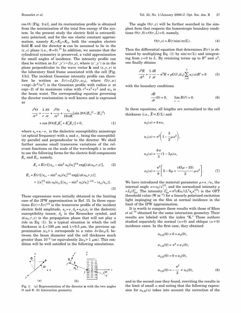
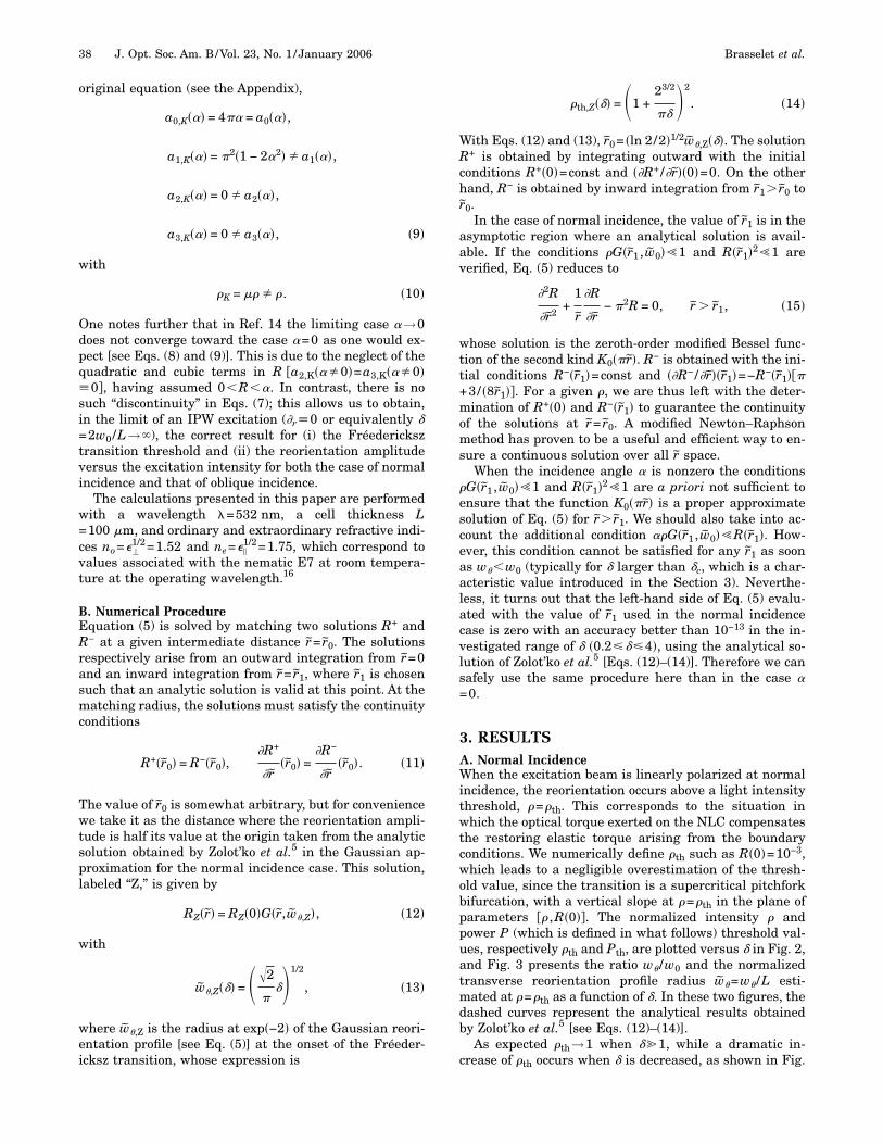
3. RESULTSA. Normal IncidenceWhen the excitation beam is linearly polarized at normalincidence, the reorientation occurs above a light intensitythreshold, �=�th. This corresponds to the situation inwhich the optical torque exerted on the NLC compensatesthe restoring elastic torque arising from the boundaryconditions. We numerically define �th such as R�0�=10−3,which leads to a negligible overestimation of the thresh-old value, since the transition is a supercritical pitchforkbifurcation, with a vertical slope at �=�th in the plane ofparameters �� ,R�0��. The normalized intensity � andpower P (which is defined in what follows) threshold val-ues, respectively �th and Pth, are plotted versus � in Fig. 2,and Fig. 3 presents the ratio w� /w0 and the normalizedtransverse reorientation profile radius w�=w� /L esti-mated at �=�th as a function of �. In these two figures, thedashed curves represent the analytical results obtainedby Zolot’ko et al.5 [see Eqs. (12)–(14)].
As expected �th→1 when � 1, while a dramatic in-crease of �th occurs when � is decreased, as shown in Fig.
38 J. Opt. Soc. Am. B/Vol. 23, No. 1 /January 2006 Brasselet et al.
2(a). Such an increase is known to arise from TNL mo-lecular correlations that are responsible for the trans-verse elastic torque exerted by unit volume onto the direc-tor
�el,� = K� �2�
�r2 +1
r
��
�r , �16�
which can be either positive (amplifying) or negative (re-storing), depending on the value of r. Since the maximumof reorientation occurs at r=0 (i.e., the central part of thebeam) the parabolic approximation R�r��R�0��1−ar2�(with a�0) is valid in the neighborhood of the origin. Itfollows that ��rrR+�rR /r�r=0=−4a�0, from which we con-clude that the molecules at the central part of the beamexperience a larger restoring torque than in the IPW case.This results in a correspondingly larger OFT intensitythreshold, since the optical torque is proportional to thelight intensity. However, one may realize that the diver-gence of the intensity threshold in the limit �→0, �th��−2, is not a singular physical behavior. Indeed, when re-alistic laser beams of finite size are considered, as madein this work, the relevant control parameter is power andnot intensity. This is illustrated in Fig. 2(b), where thenormalized power P=P0 /Plin
� at the OFT threshold Pth isplotted versus �. In this expression P0 is the total incidentpower of the beam, namely P0=2��0
�rI�r�dr= ��w02 /2�I0,
and Plin� =L2Ilin
� is a characteristic power that dependsonly on the material. In contrast to the behavior of �th inthe limiting case �→0, Pth= ���2 /8��th is finite for small �and Pth��� has a linear behavior near the origin [Fig. 2(b)].This enables one to experimentally obtain a relationshipbetween dielectric and elastic material parameters bymeasuring the threshold power for small values of � (com-pared with unity) and extrapolating the data to the originwith the help of a linear fit. Since the refractive indicescan be measured with a good accuracy,16 the extrapolatedvalue P0��=0� could be used to evaluate the elastic con-stant K. On the other hand, the divergence of Pth for large�, Pth��2, corresponds to the fact that an (ideal) infiniteplane wave carries an infinite amount of power. Finally,we mention that subsequent figures involve the normal-ized parameter � /�th that equals P /Pth and thus could bestraightforwardly exploited to analyze experimental data.The spatial extension of the reorientation profile also de-pends on the beam size, as shown in Fig. 3. As previouslydemonstrated in Ref. 14, the radius w� at exp�−2� of themaximum value of R�r� is larger (smaller) than the beamradius w0 for small (large) �. For instance, w� /w0=1 for��1.88 at �=�th. One notes that, although the ratiow� /w0 is a decreasing function of �, w� increases with �.We also see in Figs. 2 and 3 that the agreement betweenthe numerical solution (solid curves) and the analyticalexpressions obtained by Zolot’ko et al.5 is remarkablygood, losing some of its accuracy for small �. More pre-cisely, an agreement within 1% error for �th (respectively,w�) is obtained for ��1.55 (respectively, ��2.84).
From a qualitative point of view, the influence of the fi-nite beam size can in fact be gauged by the ratio betweenthe transverse and the longitudinal elastic-restoringtorque, �=�el,� /�el,z where �el,z=K�zz�, whose estimationin the central part of the beam �r=0� gives ���L /w��2.Consequently, longitudinal effects dominate, when w�
�L whereas TNL effects dominate when w��L. From Eq.(13), the intermediate situation w�=L corresponds to acharacteristic value �c�2 as one can check on Fig. 3(b).
Fig. 2. Dependence of some quantities on � for linearly polar-ized excitation at normal incidence. (a) Normalized Fréedericksztransition threshold intensity �th. (b) Normalized Fréedericksztransition threshold power Pth. Solid curve numerical result;dashed curve, analytical result obtained by Zolot’ko et al.5
Fig. 3. Dependence of some quantities on � for linearly polar-ized excitation at normal incidence. (a) Ratio w� /w0. (b) Normal-ized radius w�=w� /L. Solid curve, numerical result; dashedcurve, analytical result obtained by Zolot’ko et al.5
Brasselet et al. Vol. 23, No. 1 /January 2006 /J. Opt. Soc. Am. B 39
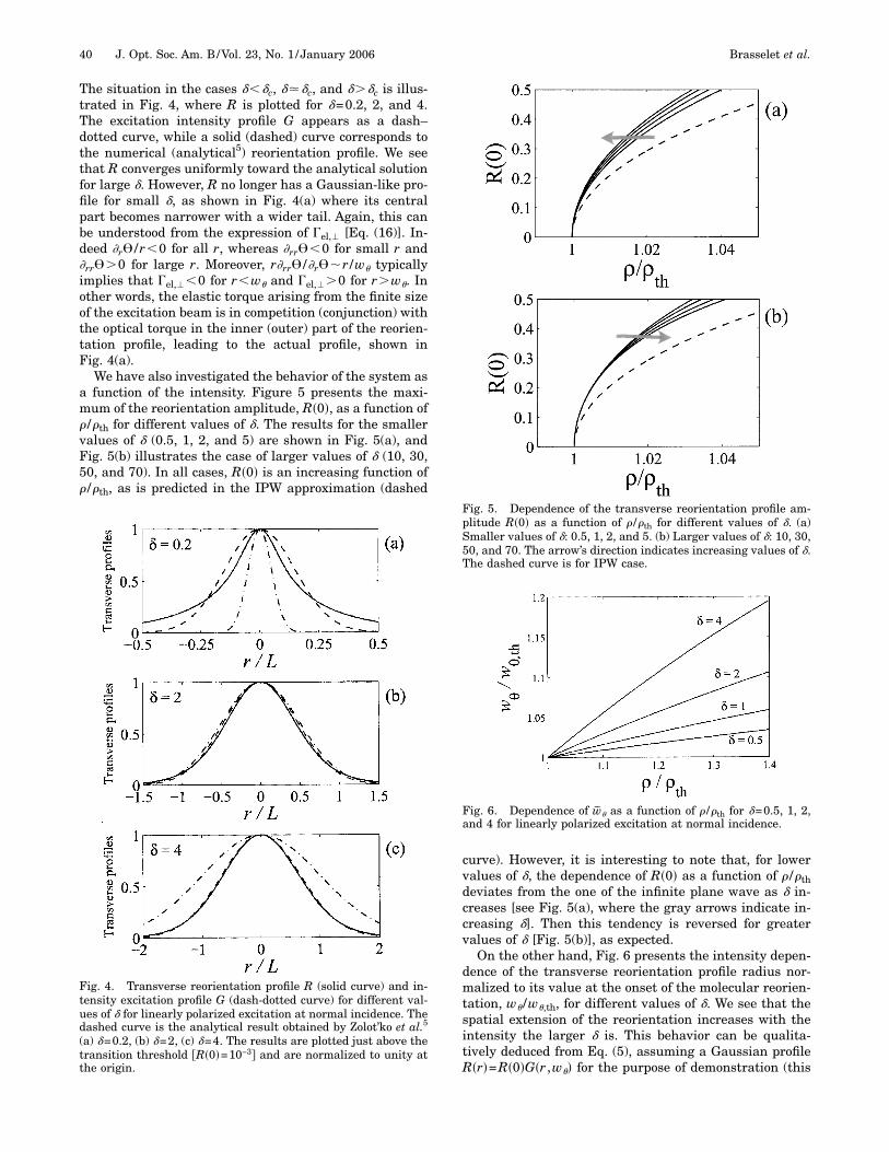
The situation in the cases ���c, ���c, and ���c is illus-trated in Fig. 4, where R is plotted for �=0.2, 2, and 4.The excitation intensity profile G appears as a dash–dotted curve, while a solid (dashed) curve corresponds tothe numerical (analytical5) reorientation profile. We seethat R converges uniformly toward the analytical solutionfor large �. However, R no longer has a Gaussian-like pro-file for small �, as shown in Fig. 4(a) where its centralpart becomes narrower with a wider tail. Again, this canbe understood from the expression of �el,� [Eq. (16)]. In-deed �r� /r�0 for all r, whereas �rr��0 for small r and�rr��0 for large r. Moreover, r�rr� /�r��r /w� typicallyimplies that �el,��0 for r�w� and �el,��0 for r�w�. Inother words, the elastic torque arising from the finite sizeof the excitation beam is in competition (conjunction) withthe optical torque in the inner (outer) part of the reorien-tation profile, leading to the actual profile, shown inFig. 4(a).
We have also investigated the behavior of the system asa function of the intensity. Figure 5 presents the maxi-mum of the reorientation amplitude, R�0�, as a function of� /�th for different values of �. The results for the smallervalues of � (0.5, 1, 2, and 5) are shown in Fig. 5(a), andFig. 5(b) illustrates the case of larger values of � (10, 30,50, and 70). In all cases, R�0� is an increasing function of� /�th, as is predicted in the IPW approximation (dashed
curve). However, it is interesting to note that, for lowervalues of �, the dependence of R�0� as a function of � /�thdeviates from the one of the infinite plane wave as � in-creases [see Fig. 5(a), where the gray arrows indicate in-creasing �]. Then this tendency is reversed for greatervalues of � [Fig. 5(b)], as expected.
On the other hand, Fig. 6 presents the intensity depen-dence of the transverse reorientation profile radius nor-malized to its value at the onset of the molecular reorien-tation, w� /w�,th, for different values of �. We see that thespatial extension of the reorientation increases with theintensity the larger � is. This behavior can be qualita-tively deduced from Eq. (5), assuming a Gaussian profileR�r�=R�0�G�r ,w�� for the purpose of demonstration (this
Fig. 4. Transverse reorientation profile R (solid curve) and in-tensity excitation profile G (dash-dotted curve) for different val-ues of � for linearly polarized excitation at normal incidence. Thedashed curve is the analytical result obtained by Zolot’ko et al.5
(a) �=0.2, (b) �=2, (c) �=4. The results are plotted just above thetransition threshold �R�0�=10−3� and are normalized to unity atthe origin.
Fig. 5. Dependence of the transverse reorientation profile am-plitude R�0� as a function of � /�th for different values of �. (a)Smaller values of �: 0.5, 1, 2, and 5. (b) Larger values of �: 10, 30,50, and 70. The arrow’s direction indicates increasing values of �.The dashed curve is for IPW case.
Fig. 6. Dependence of w� as a function of � /�th for �=0.5, 1, 2,and 4 for linearly polarized excitation at normal incidence.
40 J. Opt. Soc. Am. B/Vol. 23, No. 1 /January 2006 Brasselet et al.
has been previously shown, in Fig. 4, to be a good approxi-mation of the exact profile when � is not much smallerthan �c). A relationship between w� and � can in fact beobtained without resorting to the numerical integration ofEq. (5) by looking at this equation at the location r=rc,where the transverse elastic torque vanishes. From Eq.(16), we obtain rc=w� /�2. We obtain further from Eq. (5),in the limit of small reorientation �R�0�2�1�, the relationexp�−w�
2 /w02��1/�, whose differentiation gives
2w�dw�
w02 �
d�
�, �17�
and from which we deduce dw� /d��0.
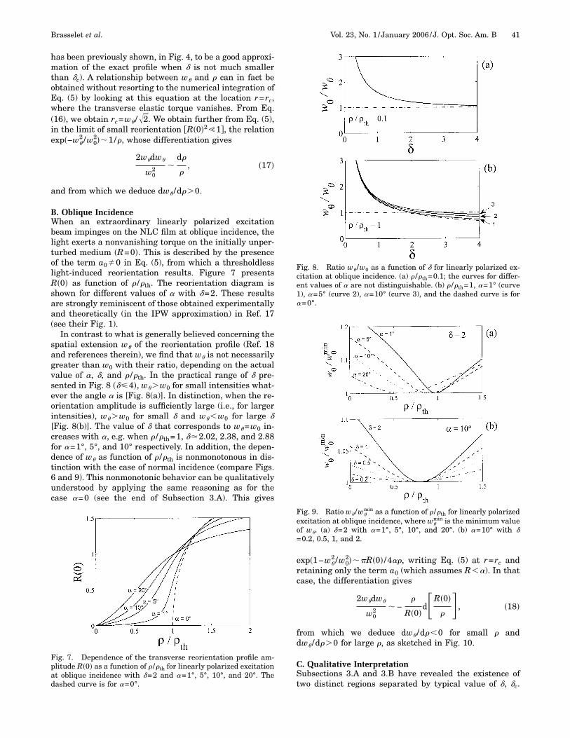
B. Oblique IncidenceWhen an extraordinary linearly polarized excitationbeam impinges on the NLC film at oblique incidence, thelight exerts a nonvanishing torque on the initially unper-turbed medium �R=0�. This is described by the presenceof the term a0�0 in Eq. (5), from which a thresholdlesslight-induced reorientation results. Figure 7 presentsR�0� as function of � /�th. The reorientation diagram isshown for different values of � with �=2. These resultsare strongly reminiscent of those obtained experimentallyand theoretically (in the IPW approximation) in Ref. 17(see their Fig. 1).
In contrast to what is generally believed concerning thespatial extension w� of the reorientation profile (Ref. 18and references therein), we find that w� is not necessarilygreater than w0 with their ratio, depending on the actualvalue of �, �, and � /�th. In the practical range of � pre-sented in Fig. 8 ���4�, w��w0 for small intensities what-ever the angle � is [Fig. 8(a)]. In distinction, when the re-orientation amplitude is sufficiently large (i.e., for largerintensities), w��w0 for small � and w��w0 for large �[Fig. 8(b)]. The value of � that corresponds to w�=w0 in-creases with �, e.g. when � /�th=1, ��2.02, 2.38, and 2.88for �=1°, 5°, and 10° respectively. In addition, the depen-dence of w� as function of � /�th is nonmonotonous in dis-tinction with the case of normal incidence (compare Figs.6 and 9). This nonmonotonic behavior can be qualitativelyunderstood by applying the same reasoning as for thecase �=0 (see the end of Subsection 3.A). This gives
exp�1−w�2 /w0
2���R�0� /4��, writing Eq. (5) at r=rc andretaining only the term a0 (which assumes R��). In thatcase, the differentiation gives
2w�dw�
w02 � −
�
R�0�d�R�0�
�� , �18�
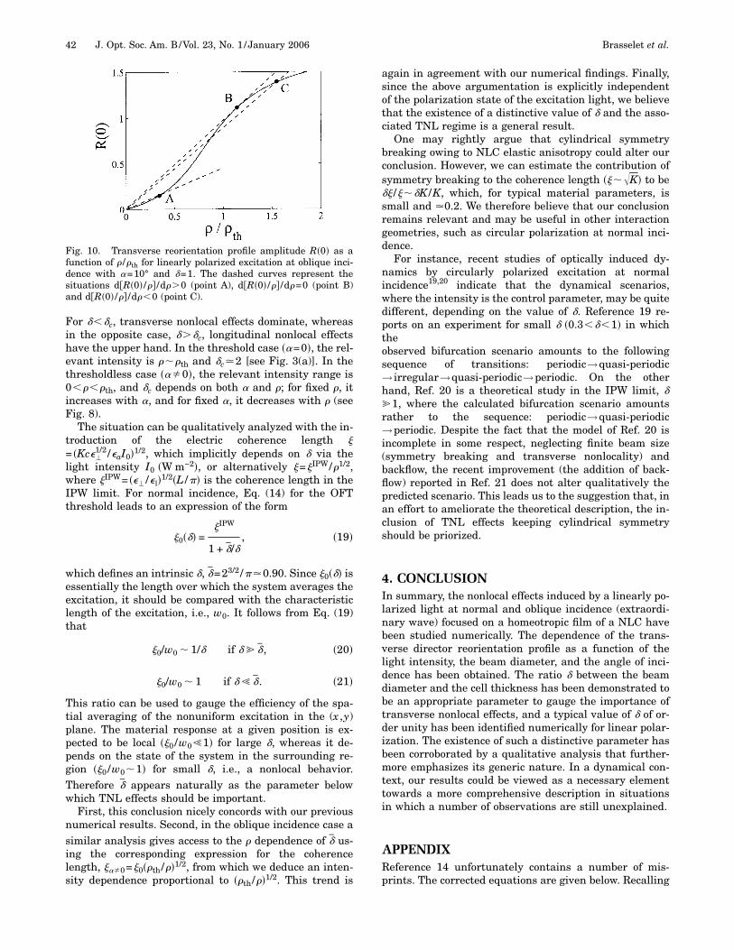
from which we deduce dw� /d��0 for small � anddw� /d��0 for large �, as sketched in Fig. 10.
C. Qualitative InterpretationSubsections 3.A and 3.B have revealed the existence oftwo distinct regions separated by typical value of �, �c.
Fig. 7. Dependence of the transverse reorientation profile am-plitude R�0� as a function of � /�th for linearly polarized excitationat oblique incidence with �=2 and �=1°, 5°, 10°, and 20°. Thedashed curve is for �=0°.
Fig. 8. Ratio w� /w0 as a function of � for linearly polarized ex-citation at oblique incidence. (a) � /�th=0.1; the curves for differ-ent values of � are not distinguishable. (b) � /�th=1, �=1° (curve1), �=5° (curve 2), �=10° (curve 3), and the dashed curve is for�=0°.
Fig. 9. Ratio w� /w�min as a function of � /�th for linearly polarized
excitation at oblique incidence, where w�min is the minimum value
of w�. (a) �=2 with �=1°, 5°, 10°, and 20°. (b) �=10° with �=0.2, 0.5, 1, and 2.
Brasselet et al. Vol. 23, No. 1 /January 2006 /J. Opt. Soc. Am. B 41
For ���c, transverse nonlocal effects dominate, whereasin the opposite case, ���c, longitudinal nonlocal effectshave the upper hand. In the threshold case ��=0�, the rel-evant intensity is ���th and �c�2 [see Fig. 3(a)]. In thethresholdless case ���0�, the relevant intensity range is0����th, and �c depends on both � and �; for fixed �, itincreases with �, and for fixed �, it decreases with � (seeFig. 8).
The situation can be qualitatively analyzed with the in-troduction of the electric coherence length �= �Kc��
1/2 /�aI0�1/2, which implicitly depends on � via thelight intensity I0 �W m−2�, or alternatively �=�IPW/�1/2,where �IPW= ��� /���1/2�L /�� is the coherence length in theIPW limit. For normal incidence, Eq. (14) for the OFTthreshold leads to an expression of the form
�0��� =�IPW
1 + �/�, �19�
which defines an intrinsic �, �=23/2 /��0.90. Since �0��� isessentially the length over which the system averages theexcitation, it should be compared with the characteristiclength of the excitation, i.e., w0. It follows from Eq. (19)that
�0/w0 � 1/� if � �, �20�
�0/w0 � 1 if � � �. �21�
This ratio can be used to gauge the efficiency of the spa-tial averaging of the nonuniform excitation in the (x ,y)plane. The material response at a given position is ex-pected to be local ��0 /w0�1� for large �, whereas it de-pends on the state of the system in the surrounding re-gion ��0 /w0�1� for small �, i.e., a nonlocal behavior.Therefore � appears naturally as the parameter belowwhich TNL effects should be important.
First, this conclusion nicely concords with our previousnumerical results. Second, in the oblique incidence case asimilar analysis gives access to the � dependence of � us-ing the corresponding expression for the coherencelength, ���0=�0��th/��1/2, from which we deduce an inten-sity dependence proportional to ��th/��1/2. This trend is
again in agreement with our numerical findings. Finally,since the above argumentation is explicitly independentof the polarization state of the excitation light, we believethat the existence of a distinctive value of � and the asso-ciated TNL regime is a general result.
One may rightly argue that cylindrical symmetrybreaking owing to NLC elastic anisotropy could alter ourconclusion. However, we can estimate the contribution ofsymmetry breaking to the coherence length ����K� to be�� /���K /K, which, for typical material parameters, issmall and �0.2. We therefore believe that our conclusionremains relevant and may be useful in other interactiongeometries, such as circular polarization at normal inci-dence.
For instance, recent studies of optically induced dy-namics by circularly polarized excitation at normalincidence19,20 indicate that the dynamical scenarios,where the intensity is the control parameter, may be quitedifferent, depending on the value of �. Reference 19 re-ports on an experiment for small � �0.3���1� in whichtheobserved bifurcation scenario amounts to the followingsequence of transitions: periodic→quasi-periodic→ irregular→quasi-periodic→periodic. On the otherhand, Ref. 20 is a theoretical study in the IPW limit, � 1, where the calculated bifurcation scenario amountsrather to the sequence: periodic→quasi-periodic→periodic. Despite the fact that the model of Ref. 20 isincomplete in some respect, neglecting finite beam size(symmetry breaking and transverse nonlocality) andbackflow, the recent improvement (the addition of back-flow) reported in Ref. 21 does not alter qualitatively thepredicted scenario. This leads us to the suggestion that, inan effort to ameliorate the theoretical description, the in-clusion of TNL effects keeping cylindrical symmetryshould be priorized.
4. CONCLUSIONIn summary, the nonlocal effects induced by a linearly po-larized light at normal and oblique incidence (extraordi-nary wave) focused on a homeotropic film of a NLC havebeen studied numerically. The dependence of the trans-verse director reorientation profile as a function of thelight intensity, the beam diameter, and the angle of inci-dence has been obtained. The ratio � between the beamdiameter and the cell thickness has been demonstrated tobe an appropriate parameter to gauge the importance oftransverse nonlocal effects, and a typical value of � of or-der unity has been identified numerically for linear polar-ization. The existence of such a distinctive parameter hasbeen corroborated by a qualitative analysis that further-more emphasizes its generic nature. In a dynamical con-text, our results could be viewed as a necessary elementtowards a more comprehensive description in situationsin which a number of observations are still unexplained.
APPENDIXReference 14 unfortunately contains a number of mis-prints. The corrected equations are given below. Recalling
Fig. 10. Transverse reorientation profile amplitude R�0� as afunction of � /�th for linearly polarized excitation at oblique inci-dence with �=10° and �=1. The dashed curves represent thesituations d�R�0� /�� /d��0 (point A), d�R�0� /�� /d�=0 (point B)and d�R�0� /�� /d��0 (point C).
42 J. Opt. Soc. Am. B/Vol. 23, No. 1 /January 2006 Brasselet et al.
that �=��r ,z� and �=0 are assumed, which implicitlymeans that K1=K2=K3, Eq. (1) should read:
F1 =K1
2�� · n�2,
=K1
2��r
2 cos2 � + �z2 sin2 � − �r�z sin 2��2;
Eq. (2),
F2 =K2
2�n · � n�2 = 0;
Eq. (3),
F3 =K3
2�n � n�2,
=K3
2��r
2 sin2 � + �z2 cos2 � + �r�z sin 2��2;
Eq. (4),
Fe = 2��� �F1�r� + F2�r� + F3�r��rdrdz;
Eq. (5),
F1�r� =K1
2��r
2 cos2 � + �z2 sin2 � − �r�z sin 2��2;
Eq. (6),
F2�r� = 0;
Eq. (7),
F3�r� =K3
2��r
2 sin2 � + �z2 cos2 � + �r�z sin 2��2.
Since the factor �� /�� is not further taken into account inthe derivation [see also their Eqs. 12, 15, 17, 19, and 21]Eq. (8) should consequently read:
F4 = −��
8�Eop
2 �r�sin2 �;
Eq. (9),
F = 2��� �F1�r� + F2�r� + F3�r� + F4�r��rdrdz;
Eq. (14),
Fe = �K�0
d
dz�0
�
��r2 + �z
2�rdr;
Eq. (17),
F = �Kd
2�0
� �R�2 + ��/d�2R2 −��
4�KEop
2 exp�− ar2�R2
+��
16�KEop
2 exp�− ar2�R4�rdr;
Eq. (18),
d
dr� �I�R,R��
�R�� −
�I�R,R��
�R;
and finally, Eq. (21) should take the form
R1��r� +R1�
r+ �b cos 2� exp�− ar2� −
�2
d2�+
2b
�exp�− ar2�sin 2� = 0.
Financial support by the National Science and Engi-neering Research Canada is gratefully acknowledged.
*Also at Laboratoire de Chimie-Physique-Matière etRayonnement, Université Pierre et Marie Curie, Paris,France.
REFERENCES1. A. S. Zolot’ko, V. F. Kitaeva, N. Kroo, N. N. Sobolev, and L.
Csillag, “Light-induced Fréedericksz transition in anMBBA crystal,” Pis’ma Zh. Eksp. Teor. Fiz. 34, 263–267(1981). [JETP Lett. 34, 250–254 (1981)].
2. B. Y. Zel’dovich, N. V. Tabiryan, and Y. S. Chilingaryan,“Fréedericksz transitions induced by light fields,” Zh. Eksp.Teor. Fiz. 81, 72–83 (1981). [Sov. Phys. JETP 54, 32–37(1981)].
3. A. S. Zolot’ko, V. F. Kitaeva, N. Sobolev, and A.Sukhorukov, “Self-focusing of laser radiation in the courseof the Fréedericksz transition in the nematic phase of aliquid crystal,” Zh. Eksp. Teor. Fiz. 81, 933–941 (1981).[Sov. Phys. JETP 54, 496–500 (1981)].
4. L. Csillag, I. Jánossy, V. F. Kitaeva, N. Kroo, N. N. Sobolev,and L. Csillag, “The influence of the finite size of the lightspot on the laser induced reorientation of liquid crystals,”Mol. Cryst. Liq. Cryst. 84, 125–135 (1982).
5. A. S. Zolot’ko, V. F. Kitaeva, V. Kuyumchyan, N. Sobolev, A.Sukhorukov, and L. Csillag, “Light-induced second-orderphase transition in a spatially bounded region of a nematicliquid crystal,” Pis’ma Zh. Eksp. Teor. Fiz. 36, 66–69 (1982).[JETP Lett. 36, 80–84 (1982)].
6. I. Drevenšek-Olenik, M. Jazbinšek, and M. Copič,“Localized soft mode at optical-field-induced Fréedericksztransition in a nematic liquid crystal,” Phys. Rev. Lett. 82,2103–2106 (1999).
7. S. D. Durbin, S. M. Arakelian, and Y. R. Shen, “Laserinduced diffraction rings from a nematic liquid crystalfilm,” Opt. Lett. 6, 411–413 (1981).
8. E. Santamato and Y. R. Shen, “Field-curvature effect on thediffraction ring pattern of a laser beam dressed by spatialself-phase modulation in a nematic film,” Opt. Lett. 9,564–566 (1984).
9. F. Bloisi, L. Vicari, F. Simoni, G. Cipparrone, and C.Umeton, “Self-phase modulation in nematic liquid-crystalfilms: detailed measurements and theoretical calculations,”J. Opt. Soc. Am. B 62, 2462–2466 (1988).
10. V. P. Romanov and D. O. Fedorov, “Anisotropy ofreorientation of the director in nematic liquid crystals atthe Fréedericksz optical transition,” Opt. Spektrosk. 78,274–280 (1995). [Opt. Spectrosc. 78, 244–250 (1995)].
Brasselet et al. Vol. 23, No. 1 /January 2006 /J. Opt. Soc. Am. B 43
11. V. P. Romanov and D. O. Fedorov, “Dynamics ofreorientation of nematic liquid crystals in the field of alight wave,” Opt. Spektrosk. 79, 313–319 (1995). [Opt.Spectrosc. 79, 288–294 (1995)].
12. M. Peccianti, C. Conti, and G. Assanto, “Interplay betweennonlocality and nonlinearity in nematic liquid crystals,”Opt. Lett. 30, 415–417 (2005).
13. M. A. Karpierz, “Solitary waves in liquid crystallinewaveguides,” Phys. Rev. E 66, 036603 (2002).
14. I. C. Khoo, T. H. Liu, and P. Y. Yan, “Nonlocal radialdependence of laser-induced molecular reorientation in anematic liquid crystal: theory and experiment,” J. Opt. Soc.Am. B 4, 115–120 (1987).
15. B. Y. Zel’dovich and N. Tabiryan, “Theory of opticallyinduced Fredericksz transition,” Zh. Eksp. Teor. Fiz. 82,1126–1146 (1982). [Sov. Phys. JETP 55, 656–666 (1982)].
16. J. Li and S. T. Wu, “Infrared refractive indices of liquidcrystals,” J. Appl. Phys. 97, 073501 (2005).
17. S. D. Durbin, S. M. Arakelian, and Y. R. Shen, “Optical-field-induced birefringence and Fréedericksz transition in anematic liquid crystal,” Phys. Rev. Lett. 47, 1411–1414(1981).
18. I. C. Khoo and S. T. Wu, Liquid Crystals-PhysicalProperties and Nonlinear Optical Phenomena (Wiley,1995).
19. E. Brasselet, B. Doyon, T. V. Galstian, and L. J. Dubé,“Optically induced dynamics in nematic liquid crystals: therole of finite beam size,” Phys. Rev. E 69, 021701 (2004).
20. E. Brasselet, T. V. Galstian, L. J. Dubé, D. O. Krimer, andL. Kramer, “Bifurcation analysis of optically induceddynamics in nematic liquid crystals: circular polarizationat normal incidence,” J. Opt. Soc. Am. B 22, 1671–1680(2005).
21. D. O. Krimer, G. Demeter, and L. Kramer, “Influence of thebackflow effect on the orientational dynamics induced bylight in nematics,” Phys. Rev. E 71, 051711 (2005).
44 J. Opt. Soc. Am. B/Vol. 23, No. 1 /January 2006 Brasselet et al.

![! f(8 X «+©J aO `}Ù.ëÜ29ï %ÿ) ã 5g^ &Íë¦ l]> ©Åá …archive.numdam.org/article/AIHPA_1997__66_4_411_0.pdf · 411 Minimizing Oseen-Frank energy for nematic liquid crystals:](https://img.pdfslide.fr/doc/110x75/5b9b088909d3f291158c725f/-f8-x-j-ao-ueue29i-y-a-5g-ie-l-aa-411-minimizing.jpg)