Advances in Engineering Software 40 (2009) 892–901
Contents lists available at ScienceDirect
Advances in Engineering Software
journal homepage: www.elsevier .com/locate /advengsoft
Integrated probabilistic framework for domino effect and risk analysis
Q.B. Nguyen a,b,*, A. Mebarki a, R. Ami Saada a, F. Mercier b, M. Reimeringer b
a Université Paris-Est, Laboratoire Modélisation et Simulation Multi Echelle, MSME FRE3160 CNRS, 5 bd Descartes, 77454 Marne-la-Vallée, Franceb Institut National de l’Environnement Industriel et des Risques (INERIS), Parc Technologique Alata BP2 60550 Verneuil en Halatte, France
a r t i c l e i n f o
Article history:Received 22 November 2007Accepted 22 January 2009Available online 25 February 2009
Keywords:Domino effectExplosionImpactTanksRiskReliability
0965-9978/$ - see front matter � 2009 Elsevier Ltd. Adoi:10.1016/j.advengsoft.2009.01.002
* Corresponding author. Address: Université Paris-et Simulation Multi Echelle, MSME FRE3160 CNRS, 5 bVallée, France.
E-mail addresses: Quoc-Bao.Nguyen@[email protected] (A. Mebarki).
a b s t r a c t
The present paper deals with domino effect analysis for industrial facilities. Actually, an explosion or acci-dent may generate various sets of projectiles. In their trajectory, they may impact other existing facilities,such as tanks under high-pressure or other strategic components or installations (headquarters, etc). Ifthe impacted targets fail, this may give rise to other sets of projectiles and so on. These potential seriesof accidents are known as domino effect. A probabilistic approach is developed by the authors. The prob-ability of domino effect occurrence requires three main steps:
– Probabilistic modelling of the source term (first set of projectiles): probability of the first explosionoccurrence and therefore number, masses, velocities, departure angles, geometrical shape and dimen-sions, constitutive materials properties are described with probabilistic distributions.
– Probabilistic modelling of the target term (first set of impacted targets): number of impacting projec-tiles, velocities, incidence angles and energy at impact, constitutive materials and the dimensions ofthe impacted targets, projectiles penetration depths into the targets are also described with probabi-listic distributions.
– Evaluation of the risks of second set of explosions that may take place in the impacted components.
Simulations (3D) are done within this probabilistic framework:
– For the probabilistic description of the source term, the authors have collected existing models fromthe literature.
– The authors propose new models for the impact (probability of impact which depends on the trajec-tory and geometry of both the target and projectile: ellipses, cylinders and planar plates, in a first step)and the penetration depth when there is impact. A simplified mechanical model is actually developedin the case of cylindrical rods impacting rectangular plates, both are metal made. The estimated pen-etration depth into the target is compared to the experimental data (4 data sets) collected from theliterature with the following features: projectile masses ranging from 0.1 g up to 250 kg, projectilevelocities ranging from 10 m/s up to 2100 m/s, projectile diameters ranging from 1.5 mm up to90 mm, target strengths ranging from 300 MPa up to 1400 MPa and incidence angles ranging from0� up to 70�.
Monte-Carlo simulations are ran in order to calculate the different probabilities: probability of impact,distribution of the penetration depth and probability of domino effect.
� 2009 Elsevier Ltd. All rights reserved.
1. Introduction
Many types of equipment under pressure may exist in industrialinstallations: tanks containing gas or highly pressurized liquids, forinstance. When reaching critical levels of overpressure, overheating
ll rights reserved.
Est, Laboratoire Modélisationd Descartes, 77454 Marne-la-
st.fr (Q.B. Nguyen), Ahmed.
or mechanical demand, a catastrophic sequence, may rise. Actually,the tanks may suddenly explode and generate many fragments thatshould be considered as projectiles threatening the other equip-ments or installations in their neighbourhood [1]. They might im-pact other equipments, penetrate them partially or perforatethem. Depending on these degrees of perforation, new accidentsmay take place in the impacted objects, leading therefore to seriesof accidents known as domino effect. Many studies deal with theprevention or mitigation of the domino effect consequences [2–6].
The present paper develops a global methodology in order tostudy the domino effect, detailing in a probabilistic framework
Nomenclature
R resistance of the impacted target (random variable hav-ing real values r)
S mechanical demand due to the projectile impact (ran-dom variable having real values s)
E limit state functionpX(x), fX(x) probability distribution (probability density function)
of the random variable X (values x)Pgen probability of fragment generationPimp probability of impactPrup probability of failurePf risk of the effect dominoC(�) Gamma cumulative density functionNsim number of simulations (Monte-Carlo simulation)g gravity (m/s2)n fragment numberLVessel vessel length (m)RVessel vessel radius (m)LFragment cylinder length in type of the oblong end-cap (m)
mp fragment mass (kg)Mt tank mass (kg)/ vertical angle of departure (rad)h horizontal angle of departure (rad)q density of the fragment constitutive material (kg/m3)CL lift coefficientCD drag coefficientvp fragment velocity (m/s)et target thickness (m)hp penetration depth (m)ecr critical thickness (m)Ec kinetic energy (J)t time (s)VFragment fragment volume (m3)VTarget target volume (m3)fu ultimate strength of the target constitutive material
(N/m2)eu ultimate strain of the target constitutive material
Q.B. Nguyen et al. / Advances in Engineering Software 40 (2009) 892–901 893
all the elementary events of the catastrophic sequence. This paperis an updated and revised version of the conference paper [7]. Theprobabilistic distributions of the whole involved parameters arederived from existing bibliography and data or are postulatedotherwise: fragment number, initial velocity, initial angles, mass,geometrical shape. . . The trajectory of the projectiles and their im-pact with surrounding objects are also investigated. Mechanicalmodels are developed in order to calculate the penetration depthand the mechanical damage caused to the impacted targets. Therisk or probability of domino effect occurrence is calculated byMonte-Carlo simulations [8–14].
2. General framework
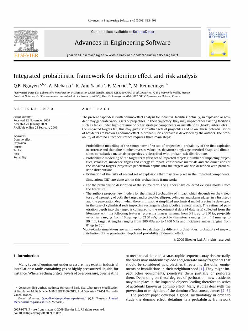
The overall domino effect sequences are described in Fig. 1a.This domino effect may be detailed by describing each of the ele-mentary steps or cycles. Each cycle requires three elementarycomponents (steps): a source term (explosion and generation ofthe fragments), the projectiles trajectory term (angles, velocitiesand displacements from the source), and the target term (impactand interaction between the projectile and the target), seeFig. 1b.
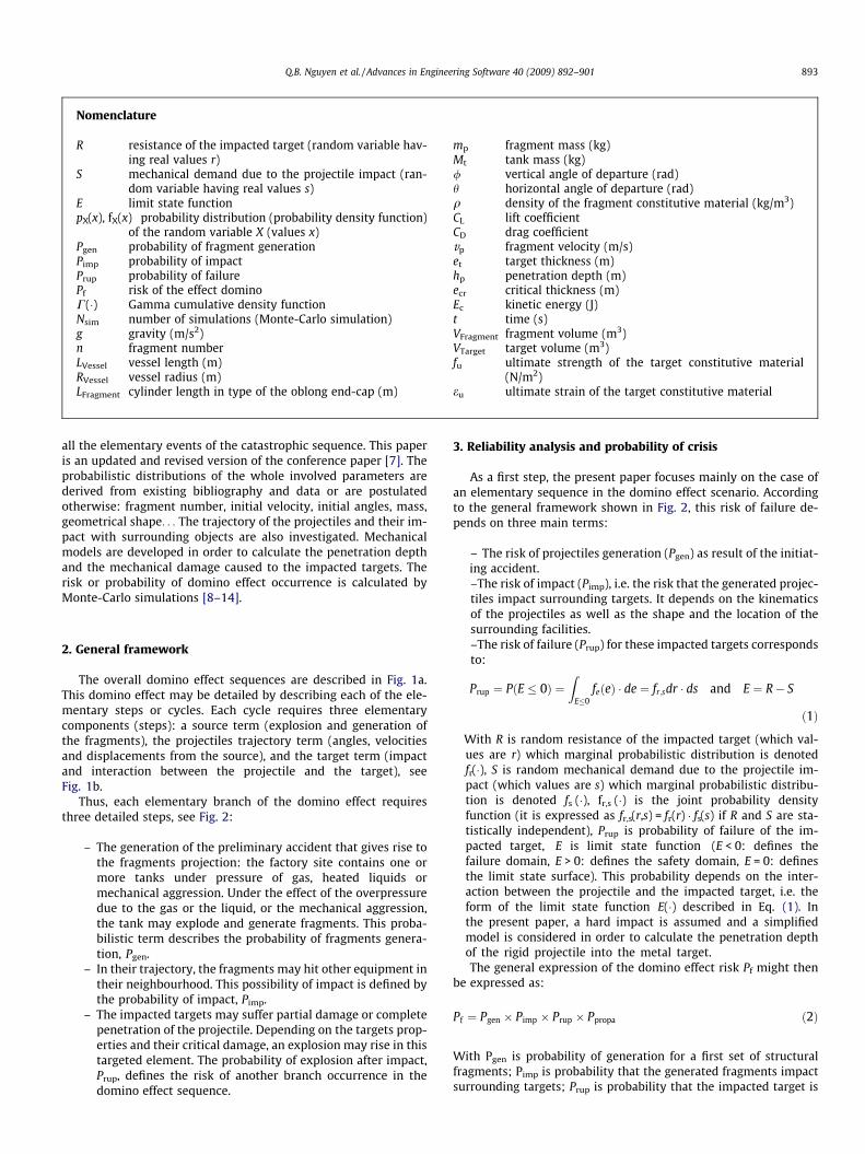
Thus, each elementary branch of the domino effect requiresthree detailed steps, see Fig. 2:
– The generation of the preliminary accident that gives rise tothe fragments projection: the factory site contains one ormore tanks under pressure of gas, heated liquids ormechanical aggression. Under the effect of the overpressuredue to the gas or the liquid, or the mechanical aggression,the tank may explode and generate fragments. This proba-bilistic term describes the probability of fragments genera-tion, Pgen.
– In their trajectory, the fragments may hit other equipment intheir neighbourhood. This possibility of impact is defined bythe probability of impact, Pimp.
– The impacted targets may suffer partial damage or completepenetration of the projectile. Depending on the targets prop-erties and their critical damage, an explosion may rise in thistargeted element. The probability of explosion after impact,Prup, defines the risk of another branch occurrence in thedomino effect sequence.
3. Reliability analysis and probability of crisis
As a first step, the present paper focuses mainly on the case ofan elementary sequence in the domino effect scenario. Accordingto the general framework shown in Fig. 2, this risk of failure de-pends on three main terms:
– The risk of projectiles generation (Pgen) as result of the initiat-ing accident.–The risk of impact (Pimp), i.e. the risk that the generated projec-tiles impact surrounding targets. It depends on the kinematicsof the projectiles as well as the shape and the location of thesurrounding facilities.–The risk of failure (Prup) for these impacted targets correspondsto:
Prup ¼ PðE � 0Þ ¼Z
E�0feðeÞ � de ¼ fr;sdr � ds and E ¼ R� S
ð1Þ
With R is random resistance of the impacted target (which val-ues are r) which marginal probabilistic distribution is denotedfr(�), S is random mechanical demand due to the projectile im-pact (which values are s) which marginal probabilistic distribu-tion is denoted fs (�), fr,s (�) is the joint probability densityfunction (it is expressed as fr,s(r,s) = fr(r) � fs(s) if R and S are sta-tistically independent), Prup is probability of failure of the im-pacted target, E is limit state function (E < 0: defines thefailure domain, E > 0: defines the safety domain, E = 0: definesthe limit state surface). This probability depends on the inter-action between the projectile and the impacted target, i.e. theform of the limit state function E(�) described in Eq. (1). Inthe present paper, a hard impact is assumed and a simplifiedmodel is considered in order to calculate the penetration depthof the rigid projectile into the metal target.The general expression of the domino effect risk Pf might then
be expressed as:
Pf ¼ Pgen � Pimp � Prup � Ppropa ð2Þ
With Pgen is probability of generation for a first set of structuralfragments; Pimp is probability that the generated fragments impactsurrounding targets; Prup is probability that the impacted target is
Source
generate
fragments
Target Target
impact, penetrate and damage
perforation (new accident)
fragment number shape mass random velocity dimensions departure angles
Target Source
Source
y mi
Target
Trajectory
z
x
vd,i fragment i
ϕi αi
mi va,i
a
b
Fig. 1. Flowchart of the effect domino (a) global view and (b) elementary event.
Identification of one accident
New accident
Determination of impact
Determination of risk
Probability of generation
Probability of impact
Probability of damage
+
-
Determination of penetration
Fig. 2. Domino effect sequences.
894 Q.B. Nguyen et al. / Advances in Engineering Software 40 (2009) 892–901
critically damaged; Ppropa is probability of accident propagation, i.e.occurrence of a new set of explosions.
4. Source terms
4.1. Source term features
An industrial accident may generate several fragments havingvarious shapes, sizes, initial velocity, and initial departure angles.It is therefore required to define correctly the distributions andthe features of the source term: fragments number, fragmentsshapes and size, their masses, their initials departure angles (hor-izontal and vertical angles), their initial velocities at departure,and their aerodynamic coefficients (lift and drag coefficients).
4.2. Fragment number
A tank explosion may generate one or many fragments accord-ing to the critical pressure, to the cracks propagation, to the tankconstitutive material and to the connection between the elemen-tary mechanical components. According to scientific reports col-lected from INERIS [15–18], the typical explosion (BLEVE) of acylindrical tank produces a limited number of massive fragments:generally two or three, and very seldom more than four or five.
Holden [5] quotes, for 31 BLEVEs having produced 76 frag-ments, an average number of 2.45 fragments, corresponding to2.87 without fire production and 2.34 with fire production. In fact,the accidents generate 1, 2, 3 or 4 fragments (except a case withoutfire). A test of BLEVE, with a carriage of 45 m3 containing 5 tons ofpropane, produced 4 fragments from the tank envelop and theBLEVE tests on propane reserves of 400 l produced 1 up to 3 frag-ments [16–18].
Moreover, according to the analysis and the experiments ofBaum [19] rupture starts with the circumferential welding and ter-minates with the split of bottom part of the tank (without or with apart of the ring). Therefore, it generates 2 up to 4 fragments: bot-tom of the tank (with or without the ring) and pieces of the ring.The size of the tank does not have an influence on the fragmentsnumber.
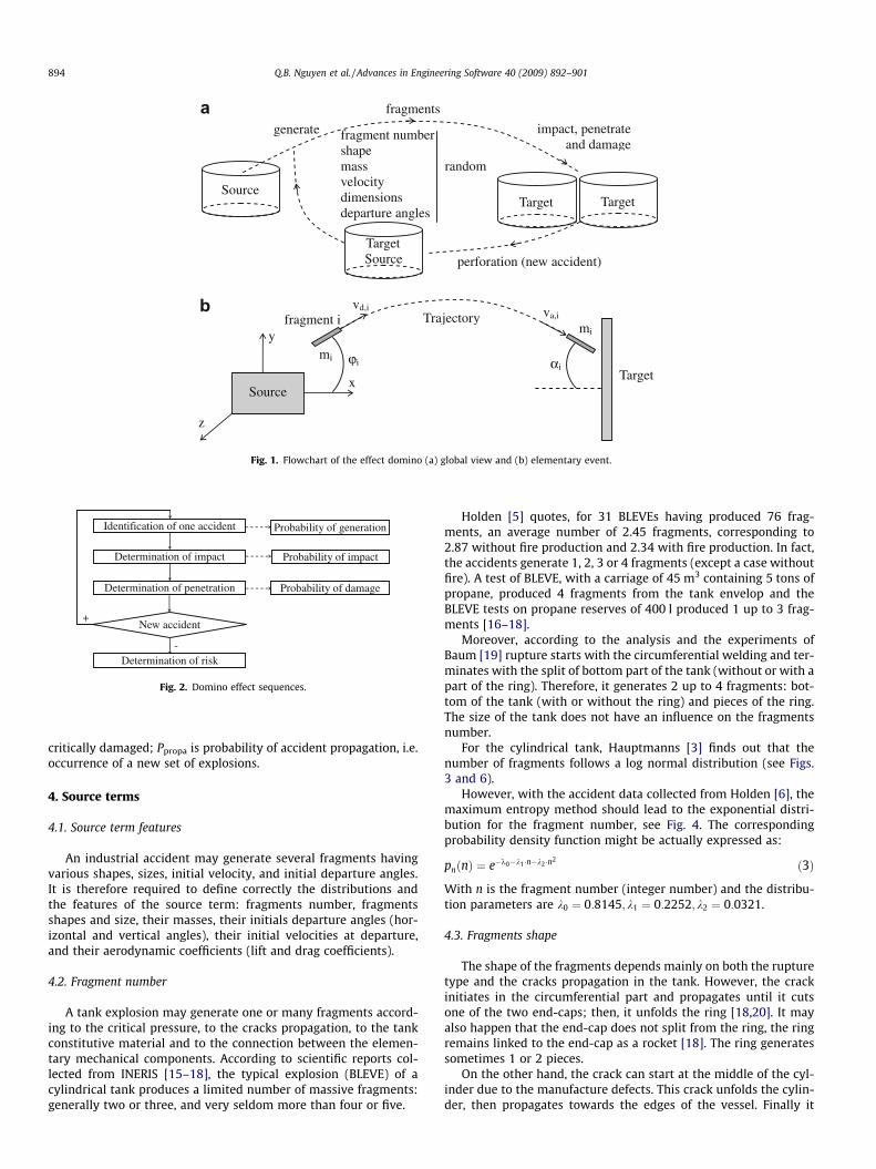
For the cylindrical tank, Hauptmanns [3] finds out that thenumber of fragments follows a log normal distribution (see Figs.3 and 6).
However, with the accident data collected from Holden [6], themaximum entropy method should lead to the exponential distri-bution for the fragment number, see Fig. 4. The correspondingprobability density function might be actually expressed as:
pnðnÞ ¼ e�k0�k1 �n�k2 �n2 ð3Þ
With n is the fragment number (integer number) and the distribu-tion parameters are k0 ¼ 0:8145; k1 ¼ 0:2252; k2 ¼ 0:0321.
4.3. Fragments shape
The shape of the fragments depends mainly on both the rupturetype and the cracks propagation in the tank. However, the crackinitiates in the circumferential part and propagates until it cutsone of the two end-caps; then, it unfolds the ring [18,20]. It mayalso happen that the end-cap does not split from the ring, the ringremains linked to the end-cap as a rocket [18]. The ring generatessometimes 1 or 2 pieces.
On the other hand, the crack can start at the middle of the cyl-inder due to the manufacture defects. This crack unfolds the cylin-der, then propagates towards the edges of the vessel. Finally it
a
b
Fig. 6. (a) Horizontal constrained tank and (b) unconstrained tank [22].
0
0.05
0.1
0.15
0.2
0.25
0.3
0.35
Acc
iden
t nu
mb
er
1 2 3 4 5 6 7 8 9
Fragment number
Accident
Model
Fig. 4. Number of fragments flying as projectiles from the cylindrical tank undergas or liquid pressure [6].
x
y
z Target
Trajectory
ϕ
x’
g Fragment
θ
Source
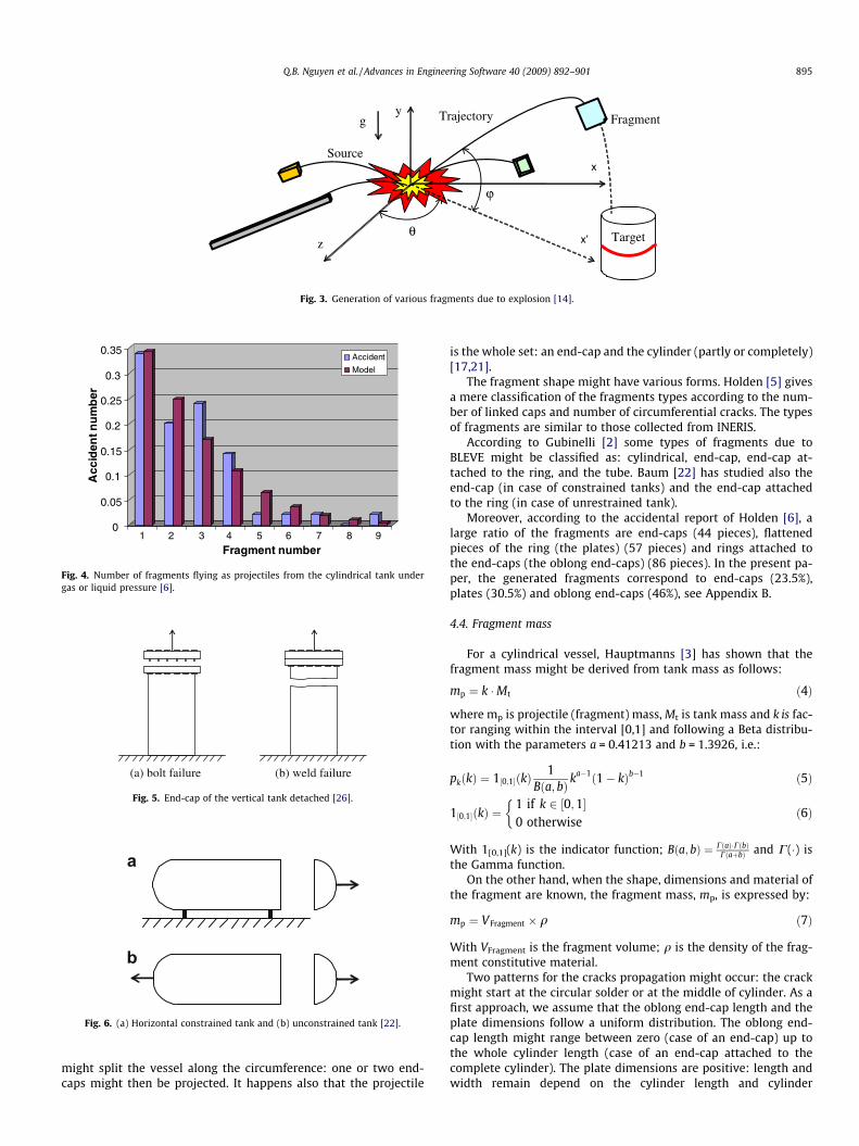
Fig. 3. Generation of various fragments due to explosion [14].
(b) weld failure (a) bolt failure
Fig. 5. End-cap of the vertical tank detached [26].
Q.B. Nguyen et al. / Advances in Engineering Software 40 (2009) 892–901 895
might split the vessel along the circumference: one or two end-caps might then be projected. It happens also that the projectile
is the whole set: an end-cap and the cylinder (partly or completely)[17,21].
The fragment shape might have various forms. Holden [5] givesa mere classification of the fragments types according to the num-ber of linked caps and number of circumferential cracks. The typesof fragments are similar to those collected from INERIS.
According to Gubinelli [2] some types of fragments due toBLEVE might be classified as: cylindrical, end-cap, end-cap at-tached to the ring, and the tube. Baum [22] has studied also theend-cap (in case of constrained tanks) and the end-cap attachedto the ring (in case of unrestrained tank).
Moreover, according to the accidental report of Holden [6], alarge ratio of the fragments are end-caps (44 pieces), flattenedpieces of the ring (the plates) (57 pieces) and rings attached tothe end-caps (the oblong end-caps) (86 pieces). In the present pa-per, the generated fragments correspond to end-caps (23.5%),plates (30.5%) and oblong end-caps (46%), see Appendix B.
4.4. Fragment mass
For a cylindrical vessel, Hauptmanns [3] has shown that thefragment mass might be derived from tank mass as follows:
mp ¼ k �Mt ð4Þ
where mp is projectile (fragment) mass, Mt is tank mass and k is fac-tor ranging within the interval [0,1] and following a Beta distribu-tion with the parameters a = 0.41213 and b = 1.3926, i.e.:
pkðkÞ ¼ 1½0;1�ðkÞ1
Bða; bÞ ka�1ð1� kÞb�1 ð5Þ
1½0;1�ðkÞ ¼1 if k 2 ½0;1�0 otherwise
�ð6Þ
With 1[0,1](k) is the indicator function; Bða; bÞ ¼ CðaÞ�CðbÞCðaþbÞ and C(�) is
the Gamma function.On the other hand, when the shape, dimensions and material of
the fragment are known, the fragment mass, mp, is expressed by:
mp ¼ VFragment � q ð7Þ
With VFragment is the fragment volume; q is the density of the frag-ment constitutive material.
Two patterns for the cracks propagation might occur: the crackmight start at the circular solder or at the middle of cylinder. As afirst approach, we assume that the oblong end-cap length and theplate dimensions follow a uniform distribution. The oblong end-cap length might range between zero (case of an end-cap) up tothe whole cylinder length (case of an end-cap attached to thecomplete cylinder). The plate dimensions are positive: length andwidth remain depend on the cylinder length and cylinder
896 Q.B. Nguyen et al. / Advances in Engineering Software 40 (2009) 892–901
circumference, and the thickness corresponds to the cylinder thick-ness, see Appendix B.
4.5. Initial velocity
It is also required to define the velocity of the fragments result-ing from an industrial accident (explosion, etc...). Aquaro and Fora-sassi [23] has performed experimental studies on a reduction scalewith mass fragments ranging within the interval [20 up to 200] kgand velocity ranging within the interval [30 up to 100] m/s, respec-tively. The fragment velocity might therefore be derived accordingto the fragment mass and the pressure before combustion.
Actually, the initial velocity of the fragments requires theknowledge of the kinetic energy (Ek) [3,4]. For this purpose, Ek isdeduced from the total energy (E), on the basis of the methods sug-gested by Baker and Baum [24–27].
From experimental studies, Baum [26] proposed the adequateformula for the end-cap velocity of vertical cylindrical tank beingdetached and being accelerated by the exit of gas due to failureof the circumferential welding, see Fig. 5. They correspond to the‘‘zero mass of end-cap” model, the ‘‘broad mass of end-cap” modeland the ‘‘velocity limit of the end-cap” model.
From other tests, Baum [22] investigated the end-cap velocityaccording to the kind of materials contained in the tank and thetemperature of the substances. Two types of fragment are investi-gated: end-cap and the end-cap linked to the ring (the rocket), [19].From the results of the tests performed by Baum [19,21,22,27], theinitial velocity is well described by a log normal distribution.
4.6. Initial departure angle
4.6.1. Vertical angleFrom the existing literature, there is no reliable information
about the horizontal angle. It is assumed therefore, as a first step,that the initial vertical angle follows a uniform distribution withinthe interval [�90�; 90�], [3,4].
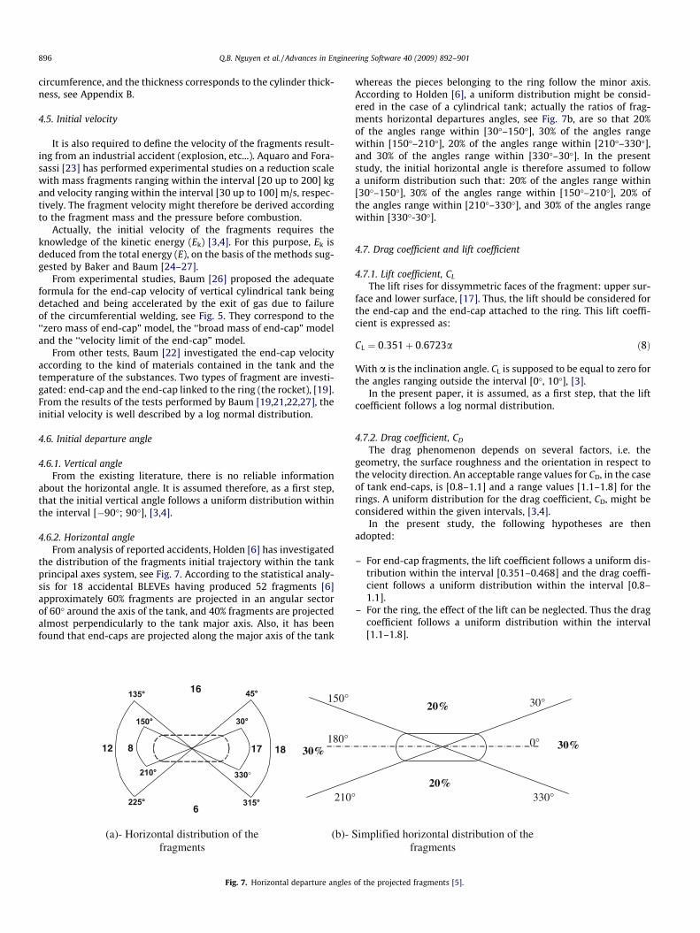
4.6.2. Horizontal angleFrom analysis of reported accidents, Holden [6] has investigated
the distribution of the fragments initial trajectory within the tankprincipal axes system, see Fig. 7. According to the statistical analy-sis for 18 accidental BLEVEs having produced 52 fragments [6]approximately 60% fragments are projected in an angular sectorof 60� around the axis of the tank, and 40% fragments are projectedalmost perpendicularly to the tank major axis. Also, it has beenfound that end-caps are projected along the major axis of the tank
30° 150°
210° 330°
17 1812
16
6
135°
225°
45°
315°
8
150°
180°
°012
30%
(a)- Horizontal distribution of the fragments
(b)- S
Fig. 7. Horizontal departure angles
whereas the pieces belonging to the ring follow the minor axis.According to Holden [6], a uniform distribution might be consid-ered in the case of a cylindrical tank; actually the ratios of frag-ments horizontal departures angles, see Fig. 7b, are so that 20%of the angles range within [30�–150�], 30% of the angles rangewithin [150�–210�], 20% of the angles range within [210�–330�],and 30% of the angles range within [330�–30�]. In the presentstudy, the initial horizontal angle is therefore assumed to followa uniform distribution such that: 20% of the angles range within[30�–150�], 30% of the angles range within [150�–210�], 20% ofthe angles range within [210�–330�], and 30% of the angles rangewithin [330�-30�].
4.7. Drag coefficient and lift coefficient
4.7.1. Lift coefficient, CL
The lift rises for dissymmetric faces of the fragment: upper sur-face and lower surface, [17]. Thus, the lift should be considered forthe end-cap and the end-cap attached to the ring. This lift coeffi-cient is expressed as:
CL ¼ 0:351þ 0:6723a ð8Þ
With a is the inclination angle. CL is supposed to be equal to zero forthe angles ranging outside the interval [0�, 10�], [3].
In the present paper, it is assumed, as a first step, that the liftcoefficient follows a log normal distribution.
4.7.2. Drag coefficient, CD
The drag phenomenon depends on several factors, i.e. thegeometry, the surface roughness and the orientation in respect tothe velocity direction. An acceptable range values for CD, in the caseof tank end-caps, is [0.8–1.1] and a range values [1.1–1.8] for therings. A uniform distribution for the drag coefficient, CD, might beconsidered within the given intervals, [3,4].
In the present study, the following hypotheses are thenadopted:
– For end-cap fragments, the lift coefficient follows a uniform dis-tribution within the interval [0.351–0.468] and the drag coeffi-cient follows a uniform distribution within the interval [0.8–1.1].
– For the ring, the effect of the lift can be neglected. Thus the dragcoefficient follows a uniform distribution within the interval[1.1–1.8].
0°
30°
°033
20%
20%
30%
implified horizontal distribution of the fragments
of the projected fragments [5].
Q.B. Nguyen et al. / Advances in Engineering Software 40 (2009) 892–901 897
5. Fragment trajectory and impact features
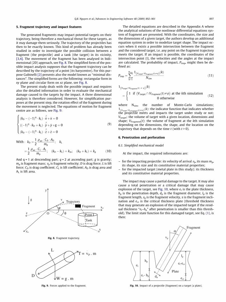
The generated fragments may impact potential targets on theirtrajectory, being therefore a mechanical threat for these targets, asit may damage them seriously. The trajectory of the projectiles hasthen to be exactly known. This kind of problem has already beenstudied in order to investigate the possible collision between afragment (the projectile) and a tank (the target) in its vicinity,[3,4]. The movement of the fragment has been analysed in bidi-mensional (2D) approach, see Fig. 8. The simplified form of the pos-sible impact analysis supposes that the fragment trajectory can bedescribed by the trajectory of a point (its barycentre). For this pur-pose Gubinelli [2] presents also the model known as ‘‘minimal dis-tances”. The simplified forms are the following: rectangular form inxy plane and circular form on xz plane, see Fig. 8.
The present study deals with the possible impact and requiresalso the detailed information in order to evaluate the mechanicaldamage caused to the targets by the impact. A three dimensionalanalysis is therefore considered. However, for simplification pur-poses at the present step, the rotation effect of the fragment duringthe movement is neglected. The equations of motion for fragmentcentre are as follows, see Fig. 9:
ðkD � ð�1Þq � kLÞ � x�2þ x
::¼ 0
ðð�1Þq � kD þ kLÞ � y�2þ y
::þg ¼ 0
ðkD � ð�1Þq � kLÞ � z�2þ z
::¼ 0
8>>>><>>>>:
ð9Þ
With : kD ¼12
qair � CD � AD
mp; kL
¼ 12
qair � CL � AL
mp; ðkD � kLÞ ¼ km; ðkD þ kLÞ ¼ kp ð10Þ
And q = 1 at descending part; q = 2 at ascending part; g is gravity;mp is fragment mass; vp is fragment velocity; D is drag force; L is liftforce; CD is drag coefficient; CL is lift coefficient; AD is drag area andAL is lift area.
y
zo
xo
Tank
Trajectoryv
θ
φ
x
g
Fragment
Point Iz O
Fig. 8. Fragment trajectory.
T = p
.
v . m
W = g . m
L
D
Fig. 9. Forces applied to the fragment.
The detailed equations are described in the Appendix A wherethe analytical solutions of the nonlinear differential equations sys-tem of fragment are presented. With the coordinates, the size andthe dimensions of a given target, the authors develop an additionalequation system in order to modelize target shape. The impact oc-curs when it exists a possible intersection between the fragmentand the considered target, i.e. any point on the fragment trajectorymeets the target. If an impact is possible, the coordinates of theintersection point (I), the velocities and the angles at the impactare calculated. The probability of impact, Pimp, might then be de-fined as:
Pimp ¼XNsim
k¼1
1 V target\VFragmentðtÞ–/ð ÞðkÞNsim
ð11Þ
1 V target\VFragmentðtÞ – /ð ÞðkÞ
¼ 1 if V target \ VFragmentðtÞ–/� �
at the kth simulation0 otherwise
(ð12Þ
where Nsim, the number of Monte-Carlo simulations;1 V target\Vk;fragmentðtÞ–/ð ÞðkÞ: the indicator function that indicates whetherthe projectile meets and impacts the target under study or not;Vtarget: the volume of target with a given location, dimensions andshape; VFragment(t): the volume of fragment at the kth simulationdepending on the dimensions, the shape, and the location on thetrajectory that depends on the time t (with t > 0).
6. Penetration and perforation
6.1. Simplified mechanical model
At the impact, the required informations are:
– for the impacting projectile: its velocity of arrival vp, its mass mp,its shape, its size and its constitutive material properties;
– for the impacted target (metal plate in this study): its thicknessand its constitutive material properties.
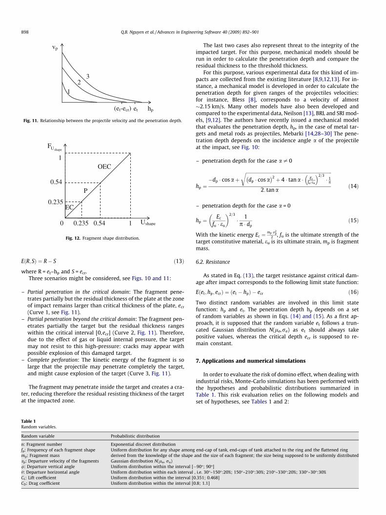
The impact may cause a partial damage to the target. It may alsocause a total penetration or a critical damage that may causeexplosion of the target, see Fig. 10, where et is the plate thickness,hp is the penetration depth, dp is the fragment diameter, lp is thefragment length, vp is the fragment velocity, a is the fragment incli-nation and ecr is the critical thickness plate (threshold thicknessthat may generate an explosion of the impacted target if the resid-ual thickness ‘‘et–hp” after penetration is smaller than this thresh-old). The limit state function for this damaged target, see Eq. (1), isthen:
dp
lp
hp
vp
α
Plate
Fragment
et
et - hp
et-ecr
ecr
Fig. 10. Impact of a projectile (fragment) on a target (a plate).
vp
hpet(et-ecr)
1
2 3
Fig. 11. Relationship between the projectile velocity and the penetration depth.
Ushape
1
0 0.235 0.54 1
P
0.235
0.54
EC
OEC
shapeUF
Fig. 12. Fragment shape distribution.
898 Q.B. Nguyen et al. / Advances in Engineering Software 40 (2009) 892–901
EðR; SÞ ¼ R� S ð13Þ
where R = et–hp and S = ecr.Three scenarios might be considered, see Figs. 10 and 11:
– Partial penetration in the critical domain: The fragment pene-trates partially but the residual thickness of the plate at the zoneof impact remains larger than critical thickness of the plate, ecr
(Curve 1, see Fig. 11).– Partial penetration beyond the critical domain: The fragment pen-
etrates partially the target but the residual thickness rangeswithin the critical interval [0,ecr] (Curve 2, Fig. 11). Therefore,due to the effect of gas or liquid internal pressure, the targetmay not resist to this high-pressure: cracks may appear withpossible explosion of this damaged target.
– Complete perforation: The kinetic energy of the fragment is solarge that the projectile may penetrate completely the target,and might cause explosion of the target (Curve 3, Fig. 11).
The fragment may penetrate inside the target and creates a cra-ter, reducing therefore the residual resisting thickness of the targetat the impacted zone.
Table 1Random variables.
Random variable Probabilistic distribution
n: Fragment number Exponential discreet distributionfp: Frequency of each fragment shape Uniform distribution for any shape amongmp: Fragment mass derived from the knowledge of the shapevp: Departure velocity of the fragments Gaussian distribution N(lu, ru)/: Departure vertical angle Uniform distribution within the interval [�h: Departure horizontal angle Uniform distribution within each intervalCL: Lift coefficient Uniform distribution within the interval [0CD: Drag coefficient Uniform distribution within the interval [0
The last two cases also represent threat to the integrity of theimpacted target. For this purpose, mechanical models should berun in order to calculate the penetration depth and compare theresidual thickness to the threshold thickness.
For this purpose, various experimental data for this kind of im-pacts are collected from the existing literature [8,9,12,13]. For in-stance, a mechanical model is developed in order to calculate thepenetration depth for given ranges of the projectiles velocities:for instance, Bless [8], corresponds to a velocity of almost�2.15 km/s. Many other models have also been developed andcompared to the experimental data, Neilson [13], BRL and SRI mod-els, [9,12]. The authors have recently issued a mechanical modelthat evaluates the penetration depth, hp, in the case of metal tar-gets and metal rods as projectiles, Mebarki [14,28–30] The pene-tration depth depends on the incidence angle a of the projectileat the impact, see Fig. 10:
– penetration depth for the case a – 0
hp ¼�dp � cos aþ
ffiffiffiffiffiffiffiffiffiffiffiffiffiffiffiffiffiffiffiffiffiffiffiffiffiffiffiffiffiffiffiffiffiffiffiffiffiffiffiffiffiffiffiffiffiffiffiffiffiffiffiffiffiffiffiffiffiffiffiffiffiffiffiffiffiffiffiffiffiffiffiffiffiffiffiffidp � cos a� �2 þ 4 � tan a � Ec
fu �eu
� �2=3� 1p
r2: tan a
ð14Þ
– penetration depth for the case a = 0
hp ¼Ec
fu � eu
� 2=3
� 1p � dp
ð15Þ
With the kinetic energy Ec ¼mp �v2
p2 , fu is the ultimate strength of the
target constitutive material, eu is its ultimate strain, mp is fragmentmass.
6.2. Resistance
As stated in Eq. (13), the target resistance against critical dam-age after impact corresponds to the following limit state function:
Eðet;hp; ecrÞ ¼ ðet � hpÞ � ecr ð16Þ
Two distinct random variables are involved in this limit statefunction: hp and et. The penetration depth hp depends on a setof random variables as shown in Eqs. (14) and (15). As a first ap-proach, it is supposed that the random variable et follows a trun-cated Gaussian distribution N(le,re) as et should always takepositive values, whereas the critical depth ecr is supposed to re-main constant.
7. Applications and numerical simulations
In order to evaluate the risk of domino effect, when dealing withindustrial risks, Monte-Carlo simulations has been performed withthe hypotheses and probabilistic distributions summarized inTable 1. This risk evaluation relies on the following models andset of hypotheses, see Tables 1 and 2:
end-cap of tank, end-caps of tank attached to the ring and the flattened ringand the size of each fragment; the size being supposed to be uniformly distributed
90�; 90�], i.e. 30�–150�:20%; 150�–210�:30%; 210�–330�:20%; 330�–30�:30%.351; 0.468].8; 1.1]
Q.B. Nguyen et al. / Advances in Engineering Software 40 (2009) 892–901 899
– Impact analysis: the possible impact is analysed for the case ofvarious shapes of the projectiles and the targets (ellipsoids, cyl-inders, rectangles) [31]. The probability of impact is evaluatedby Monte-Carlo simulations.
– The mechanical damage at the impact: the penetrationdepth is evaluated thanks to a simplified analytical model,[14,28–30]. The probability of critical damage for theimpacted tank is also calculated by Monte-Carlosimulations.
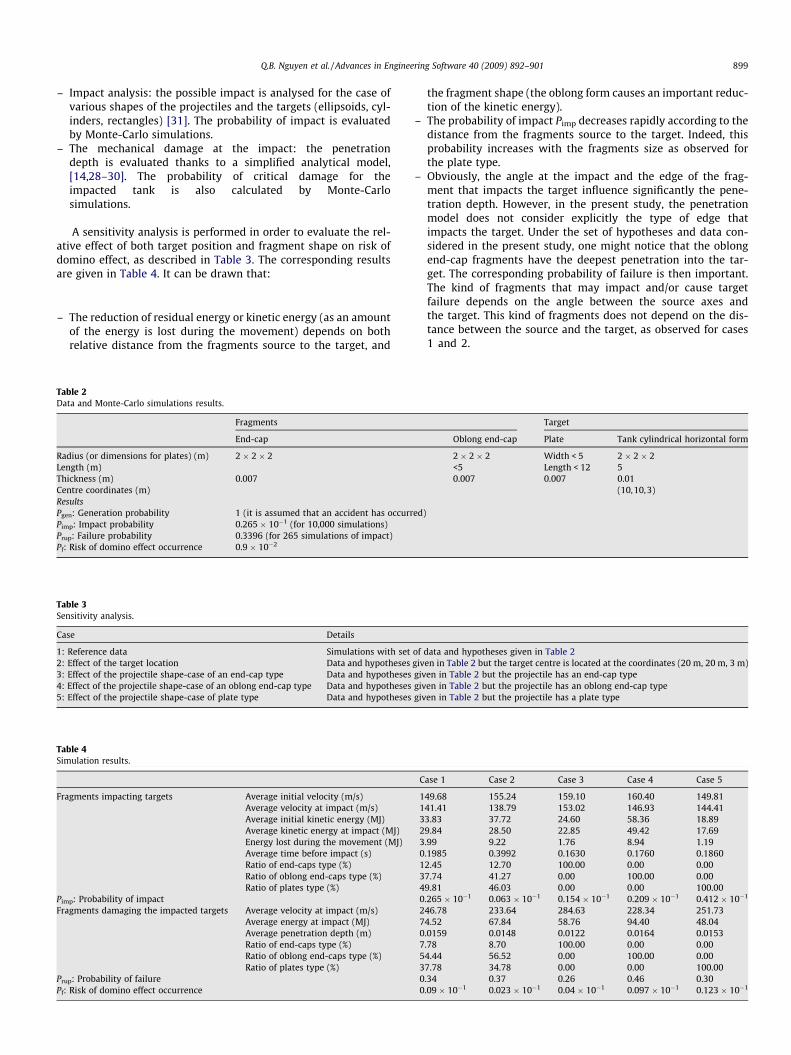
A sensitivity analysis is performed in order to evaluate the rel-ative effect of both target position and fragment shape on risk ofdomino effect, as described in Table 3. The corresponding resultsare given in Table 4. It can be drawn that:
– The reduction of residual energy or kinetic energy (as an amountof the energy is lost during the movement) depends on bothrelative distance from the fragments source to the target, and
Table 2Data and Monte-Carlo simulations results.
Fragments
End-cap
Radius (or dimensions for plates) (m) 2 � 2 � 2Length (m)Thickness (m) 0.007Centre coordinates (m)ResultsPgen: Generation probability 1 (it is assumed that an accident has occurrPimp: Impact probability 0.265 � 10�1 (for 10,000 simulations)Prup: Failure probability 0.3396 (for 265 simulations of impact)Pf: Risk of domino effect occurrence 0.9 � 10�2
Table 3Sensitivity analysis.
Case Details
1: Reference data Simulations with set2: Effect of the target location Data and hypotheses3: Effect of the projectile shape-case of an end-cap type Data and hypotheses4: Effect of the projectile shape-case of an oblong end-cap type Data and hypotheses5: Effect of the projectile shape-case of plate type Data and hypotheses
Table 4Simulation results.
Fragments impacting targets Average initial velocity (m/s)Average velocity at impact (m/s)Average initial kinetic energy (MJ)Average kinetic energy at impact (MJ)Energy lost during the movement (MJ)Average time before impact (s)Ratio of end-caps type (%)Ratio of oblong end-caps type (%)Ratio of plates type (%)
Pimp: Probability of impactFragments damaging the impacted targets Average velocity at impact (m/s)
Average energy at impact (MJ)Average penetration depth (m)Ratio of end-caps type (%)Ratio of oblong end-caps type (%)Ratio of plates type (%)
Prup: Probability of failurePf: Risk of domino effect occurrence
the fragment shape (the oblong form causes an important reduc-tion of the kinetic energy).
– The probability of impact Pimp decreases rapidly according to thedistance from the fragments source to the target. Indeed, thisprobability increases with the fragments size as observed forthe plate type.
– Obviously, the angle at the impact and the edge of the frag-ment that impacts the target influence significantly the pene-tration depth. However, in the present study, the penetrationmodel does not consider explicitly the type of edge thatimpacts the target. Under the set of hypotheses and data con-sidered in the present study, one might notice that the oblongend-cap fragments have the deepest penetration into the tar-get. The corresponding probability of failure is then important.The kind of fragments that may impact and/or cause targetfailure depends on the angle between the source axes andthe target. This kind of fragments does not depend on the dis-tance between the source and the target, as observed for cases1 and 2.
Target
Oblong end-cap Plate Tank cylindrical horizontal form
2 � 2 � 2 Width < 5 2 � 2 � 2<5 Length < 12 50.007 0.007 0.01
(10,10,3)
ed)
of data and hypotheses given in Table 2given in Table 2 but the target centre is located at the coordinates (20 m, 20 m, 3 m)given in Table 2 but the projectile has an end-cap typegiven in Table 2 but the projectile has an oblong end-cap typegiven in Table 2 but the projectile has a plate type
Case 1 Case 2 Case 3 Case 4 Case 5
149.68 155.24 159.10 160.40 149.81141.41 138.79 153.02 146.93 144.4133.83 37.72 24.60 58.36 18.8929.84 28.50 22.85 49.42 17.693.99 9.22 1.76 8.94 1.190.1985 0.3992 0.1630 0.1760 0.186012.45 12.70 100.00 0.00 0.0037.74 41.27 0.00 100.00 0.0049.81 46.03 0.00 0.00 100.000.265 � 10�1 0.063 � 10�1 0.154 � 10�1 0.209 � 10�1 0.412 � 10�1
246.78 233.64 284.63 228.34 251.7374.52 67.84 58.76 94.40 48.040.0159 0.0148 0.0122 0.0164 0.01537.78 8.70 100.00 0.00 0.0054.44 56.52 0.00 100.00 0.0037.78 34.78 0.00 0.00 100.000.34 0.37 0.26 0.46 0.300.09 � 10�1 0.023 � 10�1 0.04 � 10�1 0.097 � 10�1 0.123 � 10�1
900 Q.B. Nguyen et al. / Advances in Engineering Software 40 (2009) 892–901
8. Conclusions
The present paper deals with the domino effect in industrialfacilities. The risk representing the probability of a domino effectoccurrence as a consequence of an explosion that generates pro-jectiles is investigated. These generated projectiles may impactother industrial components (such as tanks) at their neighbour-hood. The features of the projectiles as well as the features ofthe impacted targets are described within a probabilisticframework.
Three main steps are required, i.e. a probabilistic analysis of thesource event (probability of explosion and generation of fragments,Pgen), a probabilistic analysis of the projectiles movement and theirpossible impact on targets (probability of impact, Pimp) and a prob-abilistic analysis of the target damage (probability of target rupturethat may cause a new sequence of projectiles generation leading toa domino effect, Prup).
The number of fragments, their size, their mass, their velocityat departure, and their departure angles are considered as inde-pendent random variables. During industrial accidents, the frag-ments can have a large set of shapes. However, this studyfocuses on three typical shapes of fragments: end-cap type, ob-long end-cap type and plate type. Furthermore, the study is lim-ited to the case of one projectile that can impact only onetarget.
The velocities and incidence angles at the impact of potentialtargets are also considered as independent random variables. Themechanical features of the impacted targets are described as ran-dom variables.
The mechanical models developed for this purpose evaluate theresidual depth of the targets and the penetration depth of the pro-jectiles after impact. Sometimes, the constitutive materials of thetargets and the fragments can be metal, concrete, masonry, glassand so on. The present study focuses on the case of metal targetsand metal fragments.
Monte-Carlo simulations are run and the risk of domino effect isevaluated. The domino effect is thus analyzed within the probabi-listic framework. It is shown that:
– The reduction of kinetic energy during the movement dependson both relative distance from the fragments source to the tar-get, and the fragment shape.
– The probability of impact Pimp depends on both distance fromthe fragments source to the target and fragments size.
– The kind of fragments that may impact and/or cause target fail-ure depends on the angle between the source axes and the tar-get. It does not depend on the distance between the source andthe target.
Obviously, the methodology presented in this paper can also beextended to other natural or industrial hazards: the source termcan represent any hazard effect (seismic effects and maximal accel-erations, hydraulic pressures due to rain flows or debris flows, vol-canic lavas and their thermal, mechanical and hydraulic effects,shock waves, heat and fire effects, differential soil settlementsdue to drought, etc.), the mechanical effect (or damage) dependson the mechanical behaviour or interaction of the structural com-ponent. The reliability and risk of failure of the component understudy depend intimately on the collected data, the mechanicaland physical models, as well as the probabilistic hypothesesadopted for each of the source and mechanical parts. The compo-nent failure can cause a new set of mechanical failures to othercomponents existing in its vicinity. The probabilistic methodologydeveloped for the domino effect analysis, in case of industrial acci-dents, can then be easily adapted for any other hazard and systemunder study (mechanical, electronic, and so on).
Acknowledgements
This research work has received the support of Institut Nationalde l’Environnement Industriel et des Risques (INERIS, France), as acontribution of the research project IMFRA (IMpacts of FRAgments)which financial contributors are European Community (FEDER andFSE), French national partners (FNADT, Conseil Régional Centre,Conseil Général du Cher), NEXTER munitions, French Departmentfor Ecology and Sustainable Development (MEDAD), Centre Na-tional des Risques Industriels (CNRI).
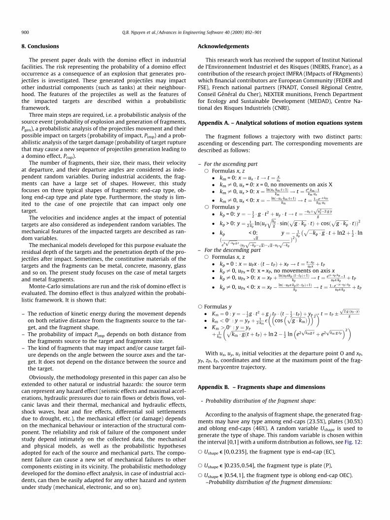
Appendix A. – Analytical solutions of motion equations system
The fragment follows a trajectory with two distinct parts:ascending or descending part. The corresponding movements aredescribed as follows:
– For the ascending parts Formulas x, z
� km = 0: x ¼ ux � t ! t ¼ xux
� km – 0, ux = 0: x = 0, no movements on axis X� km – 0, ux > 0: x ¼ lnðux �km �tþ1Þ
km! t ¼ ex �km�1
km �ux
� km – 0, ux < 0: x ¼ � ln �ux �km �tþ1ð Þkm
! t ¼ 1�e�x�km
km �ux
s Formulas y� kp = 0: y ¼ � 1
2 � g � t2 þ uy � t ! t ¼ �uy
ffiffiffiffiffiffiffiffiffiffiffiffiffiu2
y�2�g�yp
g
� kp > 0: y ¼ 12�kp
lnðuy
ffiffiffiffikpg
q� sinð
ffiffiffiffiffiffiffiffiffiffiffig � kp
p� tÞ þ cosð
ffiffiffiffiffiffiffiffiffiffiffig � kp
p� tÞÞ2
� kp < 0: y ¼ � 1kp
ffiffiffiffiffiffiffiffiffiffiffiffiffiffiffi�kp � g
p� t þ ln2þ 1
2 � ln�
ðffiffigp
e2ffiffiffiffiffiffiffi�kp �gp
�t �ðuyffiffiffiffiffiffi�kpp
� ffiffigp Þ� ffiffigp �uyffiffiffiffiffiffi�kpp Þ2Þ
– For the descending parts Formulas x, z� kp = 0 : x ¼ uPx � ðt � tPÞ þ xP ! t ¼ x�xP
uPx þ tP
� kp – 0, uPx = 0: x = xP, no movements on axis x� kp – 0, uPx > 0: x ¼ xP þ lnðuPxkp :ðt�tPÞþ1Þ
kp! t ¼ eðx�xP Þkp�1
uPx�kpþ tP
� kp – 0, uPx < 0: x ¼ xP � lnð�uPx�kpðt�tPÞþ1Þkp
! t ¼ 1�e�ðx�xP Þ�kp
uPx�kpþ tP
s Formulas y� Km ¼ 0 : y ¼ � 1
2 g � t2 þ g � tP � t � 12 � tP
� �þ yP ! t ¼ tP
ffiffiffiffiffiffiffiffiffiffiffiffiffiffiffi2�g�ðyP�yÞp
g
� km < 0 : y ¼ yP þ 12�km� cos
ffiffiffiffiffiffiffiffiffiffiffiffig � km
pÞ
� �� �2�
� Km > 0 : y ¼ yP
þ 1km
ffiffiffiffiffiffiffiffiffiffiffiffikm � g
pðt þ tPÞ þ ln 2� 1
2 ln e2ffiffiffiffiffiffiffiffikmg�tp
þ e2ffiffiffiffiffiffiffiffiffiffiffikm �g�tP
p� �2�
With ux, uy, uz initial velocities at the departure point O and xP,yP, zP, tP, coordinates and time at the maximum point of the frag-ment barycentre trajectory.
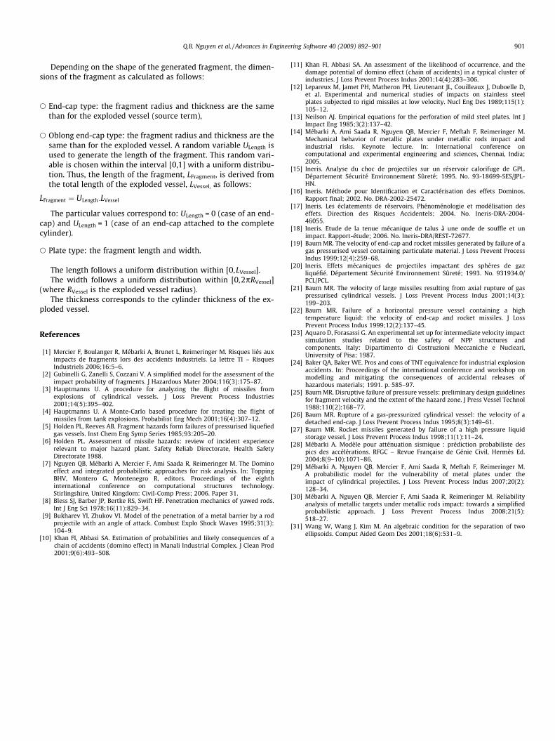
Appendix B. – Fragments shape and dimensions
- Probability distribution of the fragment shape:
According to the analysis of fragment shape, the generated frag-ments may have any type among end-caps (23.5%), plates (30.5%)and oblong end-caps (46%). A random variable Ushape is used togenerate the type of shape. This random variable is chosen withinthe interval [0,1] with a uniform distribution as follows, see Fig. 12:
s Ushape e [0,0.235], the fragment type is end-cap (EC),
s Ushape e ]0.235,0.54], the fragment type is plate (P),
s Ushape e ]0.54,1], the fragment type is oblong end-cap OEC).–Probability distribution of the fragment dimensions:
Q.B. Nguyen et al. / Advances in Engineering Software 40 (2009) 892–901 901
Depending on the shape of the generated fragment, the dimen-sions of the fragment as calculated as follows:
s End-cap type: the fragment radius and thickness are the samethan for the exploded vessel (source term),
s Oblong end-cap type: the fragment radius and thickness are thesame than for the exploded vessel. A random variable ULength isused to generate the length of the fragment. This random vari-able is chosen within the interval [0,1] with a uniform distribu-tion. Thus, the length of the fragment, LFragment, is derived fromthe total length of the exploded vessel, LVessel, as follows:
LFragment ¼ ULength:LVessel
The particular values correspond to: ULength = 0 (case of an end-cap) and ULength = 1 (case of an end-cap attached to the completecylinder).
s Plate type: the fragment length and width.
The length follows a uniform distribution within [0,LVessel].The width follows a uniform distribution within [0,2pRVessel]
(where RVessel is the exploded vessel radius).The thickness corresponds to the cylinder thickness of the ex-
ploded vessel.
References
[1] Mercier F, Boulanger R, Mébarki A, Brunet L, Reimeringer M. Risques liés auximpacts de fragments lors des accidents industriels. La lettre TI – RisquesIndustriels 2006;16:5–6.
[2] Gubinelli G, Zanelli S, Cozzani V. A simplified model for the assessment of theimpact probability of fragments. J Hazardous Mater 2004;116(3):175–87.
[3] Hauptmanns U. A procedure for analyzing the flight of missiles fromexplosions of cylindrical vessels. J Loss Prevent Process Industries2001;14(5):395–402.
[4] Hauptmanns U. A Monte-Carlo based procedure for treating the flight ofmissiles from tank explosions. Probabilist Eng Mech 2001;16(4):307–12.
[5] Holden PL, Reeves AB. Fragment hazards form failures of pressurised liquefiedgas vessels. Inst Chem Eng Symp Series 1985;93:205–20.
[6] Holden PL. Assessment of missile hazards: review of incident experiencerelevant to major hazard plant. Safety Reliab Directorate, Health SafetyDirectorate 1988.
[7] Nguyen QB, Mébarki A, Mercier F, Ami Saada R, Reimeringer M. The Dominoeffect and integrated probabilistic approaches for risk analysis. In: ToppingBHV, Montero G, Montenegro R, editors. Proceedings of the eighthinternational conference on computational structures technology.Stirlingshire, United Kingdom: Civil-Comp Press; 2006. Paper 31.
[8] Bless SJ, Barber JP, Bertke RS, Swift HF. Penetration mechanics of yawed rods.Int J Eng Sci 1978;16(11):829–34.
[9] Bukharev YI, Zhukov VI. Model of the penetration of a metal barrier by a rodprojectile with an angle of attack. Combust Explo Shock Waves 1995;31(3):104–9.
[10] Khan FI, Abbasi SA. Estimation of probabilities and likely consequences of achain of accidents (domino effect) in Manali Industrial Complex. J Clean Prod2001;9(6):493–508.
[11] Khan FI, Abbasi SA. An assessment of the likelihood of occurrence, and thedamage potential of domino effect (chain of accidents) in a typical cluster ofindustries. J Loss Prevent Process Indus 2001;14(4):283–306.
[12] Lepareux M, Jamet PH, Matheron PH, Lieutenant JL, Couilleaux J, Duboelle D,et al. Experimental and numerical studies of impacts on stainless steelplates subjected to rigid missiles at low velocity. Nucl Eng Des 1989;115(1):105–12.
[13] Neilson AJ. Empirical equations for the perforation of mild steel plates. Int JImpact Eng 1985;3(2):137–42.
[14] Mébarki A, Ami Saada R, Nguyen QB, Mercier F, Meftah F, Reimeringer M.Mechanical behavior of metallic plates under metallic rods impact andindustrial risks. Keynote lecture. In: International conference oncomputational and experimental engineering and sciences, Chennai, India;2005.
[15] Ineris. Analyse du choc de projectiles sur un réservoir calorifuge de GPL.Département Sécurité Environnement Sûreté; 1995. No. 93-18699-SES/JPL-HN.
[16] Ineris. Méthode pour Identification et Caractérisation des effets Dominos.Rapport final; 2002. No. DRA-2002-25472.
[17] Ineris. Les éclatements de réservoirs, Phénoménologie et modélisation deseffets. Direction des Risques Accidentels; 2004. No. Ineris-DRA-2004-46055.
[18] Ineris. Etude de la tenue mécanique de talus à une onde de souffle et unimpact. Rapport-étude; 2006. No. Ineris-DRA/REST-72677.
[19] Baum MR. The velocity of end-cap and rocket missiles generated by failure of agas pressurised vessel containing particulate material. J Loss Prevent ProcessIndus 1999;12(4):259–68.
[20] Ineris. Effets mécaniques de projectiles impactant des sphères de gazliquéfié. Département Sécurité Environnement Sûreté; 1993. No. 931934.0/PCL/PCL.
[21] Baum MR. The velocity of large missiles resulting from axial rupture of gaspressurised cylindrical vessels. J Loss Prevent Process Indus 2001;14(3):199–203.
[22] Baum MR. Failure of a horizontal pressure vessel containing a hightemperature liquid: the velocity of end-cap and rocket missiles. J LossPrevent Process Indus 1999;12(2):137–45.
[23] Aquaro D, Forasassi G. An experimental set up for intermediate velocity impactsimulation studies related to the safety of NPP structures andcomponents. Italy: Dipartimento di Costruzioni Meccaniche e Nucleari,University of Pisa; 1987.
[24] Baker QA, Baker WE. Pros and cons of TNT equivalence for industrial explosionaccidents. In: Proceedings of the international conference and workshop onmodelling and mitigating the consequences of accidental releases ofhazardous materials; 1991. p. 585–97.
[25] Baum MR. Disruptive failure of pressure vessels: preliminary design guidelinesfor fragment velocity and the extent of the hazard zone. J Press Vessel Technol1988;110(2):168–77.
[26] Baum MR. Rupture of a gas-pressurized cylindrical vessel: the velocity of adetached end-cap. J Loss Prevent Process Indus 1995;8(3):149–61.
[27] Baum MR. Rocket missiles generated by failure of a high pressure liquidstorage vessel. J Loss Prevent Process Indus 1998;11(1):11–24.
[28] Mébarki A. Modèle pour atténuation sismique : prédiction probabiliste despics des accélérations. RFGC – Revue Française de Génie Civil, Hermès Ed.2004;8(9–10):1071–86.
[29] Mébarki A, Nguyen QB, Mercier F, Ami Saada R, Meftah F, Reimeringer M.A probabilistic model for the vulnerability of metal plates under theimpact of cylindrical projectiles. J Loss Prevent Process Indus 2007;20(2):128–34.
[30] Mébarki A, Nguyen QB, Mercier F, Ami Saada R, Reimeringer M. Reliabilityanalysis of metallic targets under metallic rods impact: towards a simplifiedprobabilistic approach. J Loss Prevent Process Indus 2008;21(5):518–27.
[31] Wang W, Wang J, Kim M. An algebraic condition for the separation of twoellipsoids. Comput Aided Geom Des 2001;18(6):531–9.
Recommended